Table of Contents
Advertisement
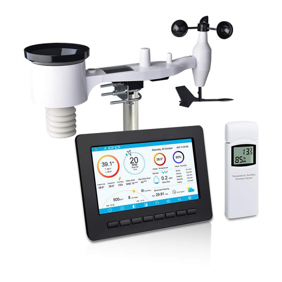
PROFESSIONAL WIFI WEATHER STATION
Operation Manual
Model: HP2551
Thank you for purchasing this Professional WIFI Weather Station! This
device provides accurate weather readings and is Wi-Fi capable to stream
data from the weather station to Internet based weather services.
This manual will guide you, step-by-step, through setting up your weather
station and console, and understanding the operation of your weather station.
Use this manual to become familiar with your professional weather station
and save it for future reference.
1
Advertisement
Table of Contents

Related Manuals for ECOWITT HP2551


Summary of Contents for ECOWITT HP2551
- Page 1 PROFESSIONAL WIFI WEATHER STATION Operation Manual Model: HP2551 Thank you for purchasing this Professional WIFI Weather Station! This device provides accurate weather readings and is Wi-Fi capable to stream data from the weather station to Internet based weather services. This manual will guide you, step-by-step, through setting up your weather station and console, and understanding the operation of your weather station.
-
Page 2: Table Of Contents
1 Table of Contents 1 TABLE OF CONTENTS..................2 2 WARNINGS AND CAUTIONS................5 3 UNPACKING......................6 4 OVERVIEW......................8 4.1 D ..................8 ISPLAY CONSOLE 4.2 I ..................... 9 NDOOR SENSOR 4.3 F ......................9 EATURES 5 SET UP GUIDE....................11 ..............11 5.1 P NSTALLATION HECKOUT... - Page 3 5.9.3 Graph Mode..................36 5.9.4 Optional Sensor Display Mode............37 5.10 S ...................37 ETTING 5.10.1 Date and Time setting..............39 5.10.2 Time Format setting................. 40 5.10.3 Date Format setting................41 5.10.4 Temperature unit setting..............41 5.10.5 Barometric unit.................. 41 5.10.6 Wind speed unit................41 5.10.7 Rainfall unit..................
- Page 4 6.2 W ................79 EATHER ORECASTING 6.3 L ..................79 IGHTNING LERT 6.4 W ......80 EATHER ORECASTING ESCRIPTION AND IMITATIONS 6.5 M ....................80 HASE 7 MAINTENANCE....................82 8 TROUBLESHOOTING GUIDE................ 84 9 SPECIFICATIONS..................... 87 10 WARRANTY INFORMATION................89...
-
Page 5: Warnings And Cautions
2 Warnings and Cautions Warning: Any metal object may attract a lightning strike, including your weather station mounting pole. Never install the weather station in a storm. If you are mounting the weather station to a house or structure, consult a licensed electrician for proper grounding. -
Page 6: Unpacking
3 Unpacking Open your weather station box and inspect that the contents are intact (nothing broken) and complete (nothing missing). Inside you should find the following: Item Description Display Console Outdoor Sensor Body with built-in: Thermo-hygrometer / Rain Gauge / Wind Speed Sensor/ Wind Direction Sensor, Light and UV sensor, Solar panel Wind speed cups (to be attached to outdoor sensor body) Wind vane (to be attached to outdoor sensor body) - Page 7 a microSD memory card. The supported max capacity of the card is 32G (Format: FAT32). A 1GB card will store more than 10 years’ worth of data, so you do not need a very large capacity card. There is also no requirement on the speed class of this card as data writing happens infrequently and is not speed critical.
-
Page 8: Overview
4 Overview 4.1 Display console Figure 1: Display console screen memory card slot USB port Power jack reset Figure 2 Display console side views Note: The USB port in the console of weather station is only for firmware update, not for data communication (USB cable not included). -
Page 9: Indoor Sensor
You can use a SD card for the firmware update.(SD card not included). Update firmware process: visit www.ecowitt.com for available update, copy “user.bin” file onto SD card main root. Insert SD card while display in operation, it will immediately show an update process, follow the instruction to complete update. - Page 10 https://www.weathercloud.com/ https://www.wow.com Custom own server data hosting possible when server data exchange is compatible with either Wunderground or Ecowitt protocol. Manage sensor calibration setup. Manage sensor via sensor ID. Data storage service on Ecowitt server: https://ecowitt.net...
-
Page 11: Set Up Guide
5 Set up Guide 5.1 Pre Installation Checkout To complete assembly you will need a Philips screwdriver (size PH0) and a wrench (size M5; included in package). Note: We suggest you assemble all components of the weather station, including console in one location so you can easily test functionality. After testing, place the outdoor sensor package in the desired location. -
Page 12: Sensor Package Assembly
structure, ground, or roof top. 3. Avoid wind and rain obstructions. The rule of thumb is to install the sensor array at least four times the distance of the height of the tallest obstruction. For example, if the building is 20’ or 6.10m tall and the mounting pole is 6’... -
Page 13: Install U-Bolts And Metal Plate
Figure 5: Sensor assembly components 1. Wind Speed cups 7. Antenna 2. Wind Vane 8. U-Bolts 3. Thermo- and hygro-meter sensors 9. Battery compartment door 4. Rain collector 10. Reset button 11. LED (red) to indicate data transmission 5. Bubble level 6. -
Page 14: Install Wind Vane
Figure 6: U-Bolt installation Loosely screw on the nuts on the ends of the U-bolts. You will tighten these later during final mounting. Final assembly is shown in Figure 7 . Figure 7: U-Bolts and nuts installed The plate and U-Bolts are not yet needed at this stage but doing this now may help avoid damaging wind vane and wind speed cups later on. -
Page 15: Install Wind Speed Cups
of friction, which is helpful in providing steady wind direction measurements. Figure 8: Wind vane installation diagram 5.3.3 Install wind speed cups Push the wind speed cup assembly onto the shaft on the opposite side of the wind vane, as shown in Figure 9 on the left side. Tighten the set screw, with a Philips screwdriver (size PH0), as shown on the right side. -
Page 16: Mount Assembled Outdoor Sensor Package
batteries and start over, but if you see the flash once every 16 seconds, everything should be OK. Figure 10: Battery installation diagram Note: If LED does not light up or is on permanently, make sure the battery is inserted the correct way and inserted fully, starting over if necessary. - Page 17 5.3.5.2 Mounting You can attach a pipe to a permanent structure and then attach the sensor package to it (see Figure 11). The U-Bolts will accommodate a pipe diameter of 1-2 inches (pipe not included). Figure 11: Sensor package mounting diagram Make sure the mounting pipe is vertical, or very close to it.
- Page 18 charging internal capacitors. Secondly it causes a zero reading for wind direction to correspond to due NORTH, as is customary. This orientation is correct for installations in the northern hemisphere. If you are installing in the southern hemisphere, the correct orientation to achieve the same optimal positioning is to have the “WEST”...
-
Page 19: Reset Button And Transmitter Led
5.3.6 Reset Button and Transmitter LED In the event the sensor array is not transmitting, reset the sensor array. Using a bent-open paperclip, press and hold the RESET BUTTON (see Figure 12) to affect a reset: the LED turns on while the RESET button is depressed, and you can now let go. -
Page 20: Multi-Channel Temperature And Humidity Sensor (Optional)
5.5 Multi-channel temperature and humidity sensor (Optional) 5.5.1 Install batteries 1. Remove the battery door on the back of the transmitter(s) by sliding down the battery door, as shown in Figure 14 . Figure 14 Battery installation for Multi-channel sensor 2. - Page 21 Figure 15: Dip Switch diagram 5. Insert two AA batteries. 6. Verify the correct channel number (CH) and temperature units of measure (°F vs. °C) are on the display, as shown in Figure 16 . Figure 16: sensor LCD display (1) temperature (2) temperature units (°F vs.
-
Page 22: Sensor Placement
5.5.2 Sensor Placement The best mounting location for the indoor sensor is in a location that never receives direct sunlight, not even through windows. Also, do not install in a location where a nearby radiant heat source (radiator, heaters, etc.) will affect it. -
Page 23: Best Practices For Wireless Communication
transmission barriers, such as walls. In general, wireless signals will not penetrate solid metal and earth (down a hill, for example). 5.6 Best Practices for Wireless Communication Wireless (RF) communication is susceptible to interference, distance, walls and metal barriers. We recommend the following best practices for trouble free wireless communication between both sensor packages and the console: ... - Page 24 Medium RF Signal Strength Reduction Glass (untreated) 5-15% Plastics 10-15% Wood 10-40% Brick 10-40% Concrete 40-80% Metal 90-100% Table: RF Signal Strength reduction...
-
Page 25: Console Display
5.7 Console Display See Figure 18 to help you identify elements of the console’s display screen. Figure 18: Display Console Screen Layout... - Page 26 Description Description Outdoor temperature Last lightning strikes detected time / distance; daily counts (optional sensor) Outdoor Feels Like/Dew Indoor humidity point/Humidity/10Min. Average Wind Direction/Max Daily Gust PM2.5 concentration(optional RF signal bar for multi-channel sensor) temperature and humidity sensor(optional sensor) RF signal bar for PM2.5 Multi-channel temperature and sensor(optional sensor) humidity sensor cycle display...
-
Page 27: Initial Display Console Set Up
5.7.1 Initial Display Console Set Up Immediately after power up (inserting power adapter), the unit will turn on the display, and the unit will start to look for reception of the indoor and outdoor sensor data. This may take up to 3 minutes. Dark Background Display Light Background Display Note: Sunrise/sunset time display will only work properly when GEO... -
Page 28: Key Functions
5.7.2 Key functions Figure 19: Buttons around the display There is a set of eight keys on the bottom of the display console. The following tables briefly explains the function of these keys. Icon Description Brightness control key Press this key to decrease the brightness Brightness control key Press this key to enhance the brightness Backlight on/off key... -
Page 29: Main Interface Icons Explain
5.7.3 Main interface icons explain 5.7.3.1 Temperature Icon Temperature Range Color Temperature Range Color (degF) Ring (degF) Ring < -10 50-60 -10 to 0 60-70 0 to 10 70-80 10-20 80-90 20-30 90-100 30-40 100-110 40-50 > 110 Note: please refer to the online manual for colorful display. - Page 30 5.7.3.2 Humidity Icon Humidity Range (%) Color Humidity Range Color Ring Ring 0%, No signal or 50 to 60 dashes 1 to 10 60 to 70 10 to 20 70 to 80 20 to 30 80 to 90 30 to 40 90 to 99 40 to 50 100%...
-
Page 31: Multiple Channel Selection And Scroll Mode
5.7.3.3 Current wind direction indication , 10-minute average wind direction indication 5.7.3.4 Hourly Rainfall Icon Hourly Rain (in) Icon Hourly Rain (in) Color Ring 0.6 to 0.8 0 to 0.2 0.8 to 1 0.2 to 0.4 1 to 1.2 0.4 to 0.6 1.2 to 1.4 5.8 Multiple Channel Selection and Scroll Mode Multi-channel sensor is an optional sensor, not included in the package. -
Page 32: History Mode
5.9 History Mode 5.9.1 View and Reset MAX/MIN While in normal display, press the key once to view and reset minimum and maximums. Figure 20: Max/Min Screen Icon Description Selection key Press this key to select the weather MAX/MIN record which need to clear Selection key Press this key to select the weather MAX/MIN record which need... -
Page 33: History Record Mode
Up arrow key Press this key to change the activated option field Down arrow key Press this key to change the activated option field History key Press this key to select History data display. Return key Press this key to return to normal display mode 5.9.2 History Record Mode While in normal display, press the key twice to enter History Record... - Page 34 Scroll left key Press this key to view the left of the scrollable area. Scroll right key Press this key to view the right of the scrollable area. Page up key Press this key to scroll up the page you are viewing Page down key Press this key to scroll down the page you are viewing History key...
- Page 35 While in History Record Mode, press the key to enter the page selection mode: Figure 23: view a specific page of history Screen Press to select a digit in a number, press to change the number. Press to change the activated option field, toggle OK or Cancel then press key to confirm.
-
Page 36: Graph Mode
5.9.3 Graph Mode While in History Record Mode, press the key once to enter Graph Mode. Press to shift the data display of 12/24/48/72H. Press to view the graph of the following data: Indoor outdoor humidity Dew Point and Feels like Indoor outdoor temperature Wind speed and Gust Wind Direction... -
Page 37: Optional Sensor Display Mode
5.9.4 Optional Sensor Display Mode For optional WH51 soil moisture sensor and WH41 PM2.5 sensor, only the first channel data will display on the main screen of the console. To view the full display of multi-channel sensors you can do this: While in Graph Mode, press the key once to enter Optional Sensor Display Mode. - Page 38 Figure 24: Setup Menu Screen Icon Description Select key Press this key to select the unit or scrolls the value Select key Press this key to select the unit or scrolls the value. Left key Press this key to select the set value. Right key Press this key to select the set value.
-
Page 39: Date And Time Setting
5.10.1 Date and Time setting While in Menu Setting Mode, press key to select Date and Time Setup field, press key to enter Date and Time Setup mode: Figure 25: Time and date Setup Screen Time setting (hour/minute/second) Press key to select time setting field, and the hour digit will turn red, press the key to change the hour setting. -
Page 40: Time Format Setting
Press key to select Date setting field, the day digit on focus turns red, press the key to change the day setting. Press to set the month, then month digit focused will turn red, press the to change the month setting. Press to set the year, the year digit on focus will turn red, press the key to change the year setting... -
Page 41: Date Format Setting
5.10.3 Date Format setting Press to change the time format between DD-MM–YYYY, YYYY-MM- DD and MM-DD-YYYY 5.10.4 Temperature unit setting Press to change the temperature units of measure between °F and °C. 5.10.5 Barometric unit Press to change the temperature units of measure between inHg, mmHg and hpa 5.10.6 Wind speed unit Press... - Page 42 Figure 26: Multi channel sensor Setup Screen Press key to select Name setting field, the name on focus turns green, press the key to pop up the keyboard to enter the sensor name. Press to scroll to the character and press to select the character.
-
Page 43: Backlight Setting
Figure 27: rename the sensor Screen Press key to select Register setting field, press the key to register the selected sensor 5.10.10 Backlight setting While in Menu Setting Mode, press key to select Backlight Setup... - Page 44 field, press key to enter backlight Setup mode: Figure 28: Backlight Setting Screen Automatic control backlight: select this option, the backlight will auto turn on and off according the set time Turn on the backlight: set the time of turning on backlight Turn off the backlight: set the time of turning off backlight Automatic brightness adjustment: select this option, the brightness will change according to the light intensity measured from outdoor sensor...
-
Page 45: Longitude: Latitude Setting
Icon Description Select key Press this key to select the unit or scrolls the value Select key Press this key to select the unit or scrolls the value. Left key Press this key to select the set value. Right key Press this key to select the set value. -
Page 46: Barometric Display
Figure 29: Longitude and Latitude Setting Screen The sunrise/sunset times will be calculating automatically base on the Longitude and Latitude. Your location GEO info can be found on mobile compass page. Two digits after decimal should be enough for this feature to be working correctly. -
Page 47: Storing Interval (1-240Minutes Selectable)
Ecowitt Weather Site: https://www.ecowitt.net Ecowitt’s new weather server that can host a bunch of sensors that other services don’t support at this time. Table: Supported weather services Note: If you are testing the setup with the outdoor sensor package nearby and indoor, you may want to consider connecting to Wi-Fi, but not yet configuring any of the weather services. - Page 48 instructions, except to use an incorrect password, on purpose! Then, after final outdoor installation, come back and change the password after clearing console history. That will start uploading to the services with a clean slate. Press key to enter Weather Server set up mode. The device can be configured to send real-time data to wunderground.com®.
- Page 49 1) Set Station ID. Press to highlight the Station ID. Enter your station ID. Press to display the keyboard. Press to scroll to the character and press to select the character. Press to return to the setup page. 2) Set Station Key. Press to highlight the station key.
- Page 50 Visit Wunderground.com and select the Join link (1) at the top of the page and select the Free (2) sign up option. Select More | Register Your PWS (3) Click Send Validation Email (4). Respond to the validation email from Wunderground.com (it may take a few minutes). Select More | Register Your PWS (5) again.
- Page 51 Your station ID will have the form: KSSCCCC###, where K is for USA station (I for international), SS is your state, CCCC is an abbreviation for your city and ### is the station number in that city. In the example above, you see station 424 in the state of Arizona (AZ) in the United States (K).
- Page 52 1) Set Station ID. Press to highlight the Station ID. Enter your station ID. Press to display the keyboard. Press to scroll to the character and press to select the character. Press to return to the setup page. 2) Set Station Key. Press to highlight the station key.
- Page 53 5.10.15.2 Viewing data on wunderground.com The most basic way to observe your weather station’s data is by using the wunderground.com web site. You will use a URL like this one, where your station ID replaces the text “STATIONID”: http://www.wunderground.com/personal-weather-station/dashboard?ID=ST ATIONID It will show a page such as this, where you can look at today’s data and historical data as well: There are also some very useful mobile apps.
- Page 54 WU Storm: iPad and iPhone application for viewing radar images, animated wind, cloud coverage and detailed forecast, and PWS station data https://itunes.apple.com/us/app/wu-storm/id955957721...
- Page 55 Weather Underground: Forecast: iOS and Android application for forecasts https://itunes.apple.com/us/app/weather-underground-forecast/id486154 https://play.google.com/store/apps/details?id=com.wunderground.andro id.weather&hl=en PWS Weather Station Monitor: View weather conditions in your nei ghborhood, or even right in your own backyard. Connects to wunderg round.com...
- Page 56 5.10.15.3 Registering with and using Ecowitt Weather You can also use the Ecowitt Weather server to monitor and record all your sensors’ data. Configure as follows: On the Weather Server page, set the reporting interval time(default: 1 minute).
- Page 57 Note: If you want to share your station data with other users, you’ll need to set your data to be public. Other users need to log in the ecowitt.net first to view your data. It will show a page such as this, where you can look at today’s data and historical data as well.
- Page 58 Graph display List display...
- Page 59 Weather Map Email Alerts...
- Page 60 Press the “setup” button to enter Customized setup screen, Figure 32 : Server setup screen Select Enable button and select the protocol type. The website should has the same protocol with Wunderground or Ecowitt. Input all the information needed.
-
Page 62: Connect Console To Your Router: Wi-Fi Scan
5.10.16 Connect Console to Your Router: Wi-Fi scan Entering this mode, system will display all the available Wi-Fi networks. Select the SSID that you want console to be connected with (only supports 2.4GHz band Wi-Fi network ) , and enter passer word as required. Press key to select the Wi-Fi network. - Page 63 If the Wi-Fi network you would like to connect is with a hidden SSID, please follow below steps to connect: 1) Press to select Hidden SSID setup, and press directly to enter. 2).Press to highlight the SSID. Press to display the keyboard and enter your SSID.
-
Page 64: Background
5.10.17 Background While in Menu Setting Mode, press key to select Background Setup field, press key to choose between dark background display and light background display... -
Page 65: Alarm Setting Mode
5.11 Alarm Setting Mode Icon Description Select key Press this key to select the unit or scrolls the value Select key Press this key to select the unit or scrolls the value. Left key Press this key to select the set value. Right key Press this key to select the set value. -
Page 66: Calibration Mode
until the weather condition doesn’t meet the user set level. Press any key to mute the alarm. 5.12 Calibration Mode Icon Description Select key Press this key to select the unit or scrolls the value Select key Press this key to select the unit or scrolls the value. Left key Press this key to select the set value. - Page 67 To adjust the parameter, press to scroll to the parameter you wish to change. Press to highlight the sign (positive vs. negative, if applicable) and significant digit. Press to change the calibrated value. Parameter Type of Default Typical Calibration Source Calibration Temperature Offset...
- Page 68 margin of error. Using a local weather station in your area is also a poor source due to changes in location, timing (airport weather stations are only updated once per hour) and possible calibration errors (many official weather stations are not properly installed and calibrated).
- Page 69 The standard sea-level pressure is 29.92 in Hg (1013 mb). This is the average sea-level pressure around the world. Relative pressure measurements greater than 29.92 inHg (1013 mb) are considered high pressure and relative pressure measurements less than 29.92 inHg are considered low pressure. To determine the relative pressure for your location, locate an official reporting station near you (the internet is the best source for real time barometer conditions, such as Weather.com or...
- Page 70 Without a calibrated source, wind speed can be difficult to measure. We recommend using a calibrated wind meter (not included) and a constant speed, high speed fan. Note: If located in southern hemisphere, please follow the steps to calibrate the wind direction: 1.Install the outdoor sensor package with the West arrow on the sensor pointing due East.
-
Page 71: More
Calibration is only useful if you have a known calibrated source you can compare it against, and is optional. This section discusses practices, procedures and sources for sensor calibration to reduce manufacturing and degradation errors. Do not compare your readings obtained from sources such as the internet, radio, television or newspapers. - Page 73 Note: To calibrate the optional soil moisture sensor, please refer to the manual of the WH51 soil moisture senor. To calibrate the PM2.5 sensor, you’ll need to find a reliable source, such as professional devices from your local air quality service. To calibrate the temp and humidity sensor, please refer to section 4.9.19.
-
Page 75: Factory Reset
5.14 Factory reset 5.14.1 Re-register indoor transmitter Press key to select re-register indoor transmitter. Press key to popup the Message Box ”Register a new indoor transmitter?” Press to select Yes or No. Press the key to confirm the selection. 5.14.2 Re-register outdoor transmitter Please reference section 5.13.1. -
Page 76: Reset To Factory
key to switch on/off. When it is selected with ON option, min/max will be presented as daily min/max, and with OFF option selected, it is for history min/max record. 5.14.4 Reset to Factory Press key to select Reset to Factory. Press to popup the Message Box ”Reset to factory default?”... -
Page 77: Backup Data
5.14.7 Backup data Press key to select Backup data. Press key to popup the Message Box ”Copy history data to SD card?” Press to select OK or Cancel. Press the key to confirm the selection. Note: You need to insert a SD card(not included) into the console before using this function. -
Page 78: Other Console Functions
6 Other Console Functions 6.1 Beaufort Wind Force Scale If you have selected the use of Beaufort wind speed units, you can use the table below for reference. The Beaufort scale is based on qualitative wind conditions and how they would affect a ship’s (frigate) sails (so yes, it is an “old”... -
Page 79: Weather Forecasting
6.2 Weather Forecasting The five weather icons are Sunny, Partly Cloudy, Cloudy, Rainy and Stormy. The forecast icon is based on the rate of change of barometric pressure. Please allow at least one month for the weather station to learn the barometric pressure over time. -
Page 80: Weather Forecasting Description And Limitations
6.4 Weather Forecasting Description and Limitations In general, if the rate of change of pressure increases, the weather is generally improving (sunny to partly cloudy). If the rate of change of pressure decreases, the weather is generally degrading (cloudy, rainy or stormy). - Page 81 Day 3 Day 16 Day 4 Day 17 Day 5 Day 18 Day 6 Day 19 Day 7 Day 20 Day 8 Day 21 Day 9 Day 22 Day 10 Day 23 Day 11 Day 24 Day 12 Day 25 Day 13 Day 26 Full Moon...
-
Page 82: Maintenance
7 Maintenance The following steps should be taken for proper maintenance of your station Clean the rain gauge once every 3 months. Rotate the funnel counter-clockwise and lift to expose the rain gauge mechanism, and clean with a damp cloth. Remove any dirt, debris and insects. If bug infestation is an issue, spray the array lightly with insecticide. - Page 83 When replacing the batteries, apply a corrosion preventing compound on the battery terminals, available at Amazon and most hardware stores. In snowy environments, spray the top of the weather station with anti-icing silicon spray to prevent snow build up.
-
Page 84: Troubleshooting Guide
8 Troubleshooting Guide Look through the following table and locate an issue or problem you are experiencing in the left column and read possible solutions in the right column. Problem Solution Wireless remote The maximum line of sight communication range is about (thermo-hygrometer) not 300’. - Page 85 Problem Solution it from the rest of the sensors). The LED next to the battery compartment will flash every 16 seconds. If the LED is not flashing every 16 seconds… Replace the batteries in the outside sensor array. If the batteries were recently replaced, check the polarity. If the sensor is flashing every 16 seconds, proceed to the next step.
- Page 86 Problem Solution Wundeground.com, not the station). Example, $oewkrf is not a valid password, but oewkrf$ is valid. Confirm your station ID is correct. The station ID is all caps, and the most common issue is substituting an O for a 0 (or visa versa). Example, KAZPHOEN11, not KAZPH0EN11 If there's a number "1"...
-
Page 87: Specifications
9 Specifications Note: Out of range values will be displayed using “---”: Outdoor sensor Specification Transmission distance in open field 100 m (330 ft.) RF Frequency 433 / 868 / 915 MHz depending on location United States: 915 MHz Temperature range -40°C –... - Page 88 Indoor sensor Specification Temperature range -10°C – 60°C (14°F - 140°F) Temperature resolution 0.1°C, or 0.1°F Humidity range 10% ~ 99% Humidity resolution Barometric pressure range 300 – 1,100 hPa (8.85 – 32.5 inHg) Barometric pressure accuracy ± 3 hPa in 700 – 1,100 hPa range Barometric pressure resolution 0.1 hPa (0.01 inHg) Sensor reporting interval...
-
Page 89: Warranty Information
10 Warranty Information We disclaim any responsibility for any technical error or printing error, or the consequences thereof. All trademarks and patents are recognized. We provide a 1-year limited warranty on this product against manufacturing defects, or defects in materials and workmanship. This limited warranty begins on the original date of purchase, is valid only on products purchased, and only to the original purchaser of this product.
Need help?
Do you have a question about the HP2551 and is the answer not in the manual?
Questions and answers
i AM GETTING DASHES ON THE DISPLAY OF OUR ECOWITT hp2551ca WEATHER STATION. tHE MANUAL SAYS SEE SECTION 5.13.2 FOR INSTRUCTIONS ON HOW TO RESYNCHRONIZE. tHERE DOES NOT APPEAR TO BE A 5.13.2 IN THE MANUAL OR ONLINE. cOULS YOU PLEASE GIVE ME THE INSTRCUTIONS ON HOW TO SYNCHRONIZE