
Related Manuals for D-Box 3250i


Summary of Contents for D-Box 3250i
- Page 1 3250i ACTUATORS (3 actuators, 3 axis system) INSTALLATION GUIDE Technical Support : 1-888-442-3269 ext. 264 Fax : 450-442-3230 E-mail : techsupport@d-box.com Visit us at : www.d-box.com 156-914-0009-EN3...
-
Page 2: Table Of Contents
PC Motion Controller (MCI-4P or MCI-2P) ................11 PC Motion Controller (KAI-1P) ....................11 Technical Drawings ........................12 D-BOX 3250i Actuator Dimensions (.75” Bracket) ..............12 Actuator Control Module (ACM) Dimensions ................12 Connections to the ACM Unit ....................13 Connections to the ACM Unit .................... - Page 3 IMPORTANT SAFETY INSTRUCTIONS Read these instructions. Keep these instructions. Heed all warnings. Follow all instructions. Do not use this apparatus near water. Clean only with dry cloth. Do not block any ventilation openings. Install in accordance with the manufacturer's instructions. Do not install near any heat sources such as radiators, heat registers, stoves, or other apparatus (including amplifiers) that produce heat.
- Page 4 EXTREMELY HIGH VOLTAGE. SERIOUS INJURY OR DEATH COULD OCCUR IF HANDLED WHILE IN OPERATION. The D-BOX 3250i Actuator System is designed to be installed into the armrest of qualified home theater seating. When properly installed, the system will give you a three (3) axis motion designed for home entertainment.
-
Page 5: Components And Required Tools
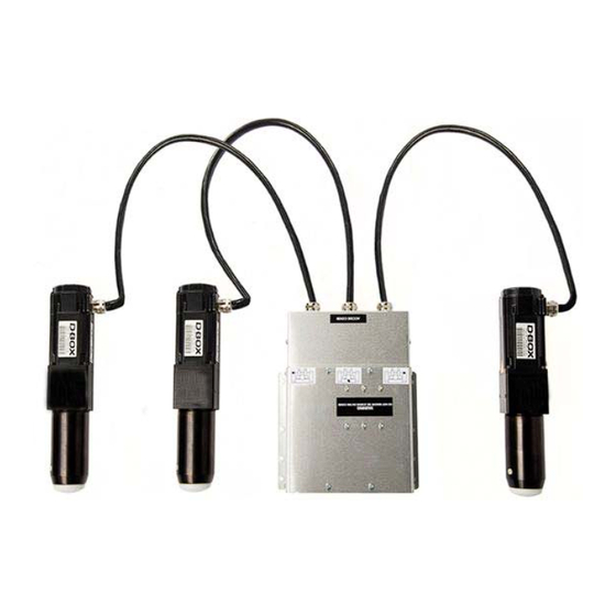
1 Components and Required Tools Description Quantité ACM Unit (Actuator Control Module) Actuator Power Cable, 6 feet (000-090-0010-Z00) Single Cup, Aluminum (810-0002) Screw, Bolt, Hex, Cap, 1/4-20 X 3/4, Black (100-0551)) Washer, Lock, 1/4, Black (102-0051) Included with the L/U bracket option (#801-0001) Washer, Lock, tooth, 1/4, Zn (102-0053) Screw, Bolt, Hex, Cap, 1/4-20 X 1, Black (000-100-0555-Z00) Tiewrap, 7 3/8"... -
Page 6: Actuators
2 Actuators 2.1 Setting the ACM Set the ACM, with the actuators attached, in front of the installation you have chosen. 2.2 Front Right Actuator Place the front right actuator (identified with a sticker on the ACM). Note that the right side of the installation is actually on your left, as you face the installation. -
Page 7: Front Left Actuator
Use center holes Slide the actuator with its brackets back into the square hole of the installation and secure it with four (4) of the supplied bolts and lock washers, through the predrilled holes. Do not over tighten the bolts. Damage to the tee nut could occur. 2.3 Front Left Actuator Repeat previous steps for the left actuator. -
Page 8: Acm
3 ACM 3.1 Placing the ACM Place the ACM into the installation where it will not interfere with the any other mechanism. 3.2 Securing the ACM Secure the ACM to the bottom panel of the installation using the supplied bolts and lock washers into the predrilled holes. -
Page 9: Cables
4 Cables WARNING! WHEN SECURING CABLES TO THE INSTALLATION, BE CAREFUL NOT TO DAMAGE THE ACTUATOR CABLES. ENSURE CABLES ARE SECURED IN A WAY THAT THEY CANNOT BE PINCHED BY ANY MOVING PARTS. THESE CABLES HAVE VERY HIGH VOLTAGE. IMPROPER HANDLING OR INSTALLATION COULD CAUSE SERIOUS INJURY OR DEATH. -
Page 10: Tests
5 Tests 5.1 Routing the Cables Set the 3250i in its final position. Route the CAT5 and power cables from the back of the ACM (Actuator Control Module) ensuring they do not interfere, go under or near any of the actuators. -
Page 11: Pc Motion Controller (Mci-4P Or Mci-2P)
5.4 PC Motion Controller (MCI-4P or MCI-2P) Power on your PC and launch the D-BOX Motion Controller Interface. In the Main menu, switch the Mode to “Demo.” The chair will cycle through test movements. 5.5 PC Motion Controller (KAI-1P) The KAI-1P device automatically controls one KineLink platform without user intervention. -
Page 12: Technical Drawings
6 Technical Drawings 6.1 D-BOX 3250i Actuator Dimensions (.75” Bracket) 6.2 Actuator Control Module (ACM) Dimensions 12 of 15... -
Page 13: Connections To The Acm Unit
6.3 Connections to the ACM Unit 6.4 Connections to the ACM Unit 13 of 15... -
Page 14: D-Box 3250I Electrical Diagram
6.5 D-BOX 3250i Electrical diagram 14 of 15... -
Page 15: Appendix 1 Installation Of The Acm Bracket
Appendix 1 Installation of the ACM bracket 15 of 15...
Need help?
Do you have a question about the 3250i and is the answer not in the manual?
Questions and answers