Advertisement
Table of Contents
- 1 Table of Contents
- 2 Important Safety Instructions
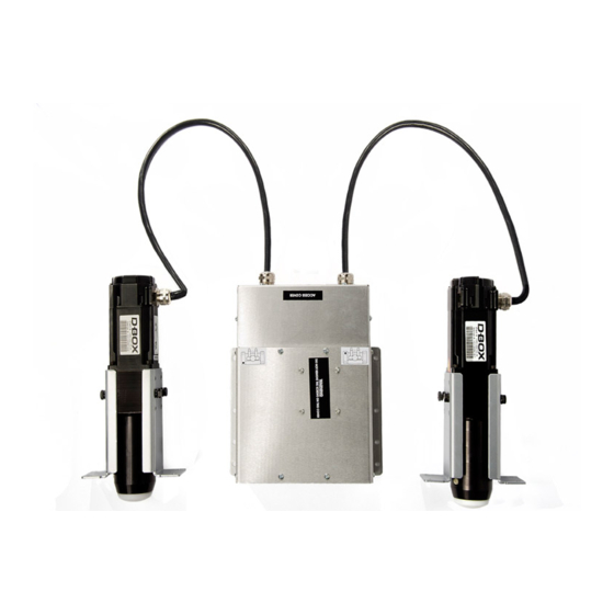
- 3 1- D-BOX 4250I/4400I, 3 Axis Actuators System Overview
- 4 2- D-BOX 4250I/4400I System Dimensions and Setup
- 5 3- Positioning the Components
- 6 4- Positioning the Actuators (Bottom View of Seating)
- 7 5- Arm Rest Mounting Hole Dimensions
- 8 6- Setting up the Actuators in the Seat
- 9 7- Connecting the Actuators to the ACM (Actuator Control Module)
- 10 8- D-BOX 4250I/4400I Electrical Diagram
- 11 9- Pictures of D-BOX Installation (in a Loveseat)
- 12 Appendix 1 - Installation of the ACM Bracket
- Download this manual
Advertisement
Table of Contents


Need help?
Do you have a question about the 4250i and is the answer not in the manual?
Questions and answers
Hello, I purchased 4 gen 5 4250 actuators from a company called Trak Racer. Each actuator has a diagram showing the position they should be installed however, none of the diagrams I have show a mark indicating where they should be properly placed. Does it matter or am I in trouble. Without a mark on any of the diagrams I have no idea where to install them. I am using them for a race simulation cockpit so I need to place them front left/right and back left/right. Lastly, I noticed each actuator has a voltage switch (120v and 230v). I live in the US so I need them on 120v however, I'm not sure which way the switch should be flipped to choose the correct voltage. Can you send me an image or explanation so I know that I have the voltage switch on the correct (120v) setting. Thanks for your time.
To install the D-Box 4250i actuators in a race simulation cockpit:
1. Position the Actuators: Place the four actuators in their designated positions:
- Front Right: Port A (D)
- Front Left: Port B (G)
- Rear Left: Port C (J)
- Rear Right: Port D (M)
2. Mounting:
- Attach the actuators to the rig using mounting brackets.
- Secure them with screws to ensure stability.
- Ensure the actuators are aligned correctly for proper motion feedback.
3. Connection:
- Connect the actuators to the Actuator Control Module (ACM) using Cat 5 cables.
- Ensure each actuator is plugged into its corresponding port.
4. Configuration:
- In the software, select four actuators and enable roll, pitch, and heave.
- Apply the configuration and wait for the system to load.
To set the voltage switch to 120V:
- Locate the voltage selector at the bottom of the control electronics.
- Switch it to 120V if using in regions with 120V power supply (e.g., North America).
This answer is automatically generated