Advertisement
Quick Links
Diagram 2
Diagram 2A
We reserve the right to change specification without prior warning
Manrose is proudly distributed by Ventair Pty Ltd
4 Capital Place, Carrum Downs, 3201 VIC, AUSTRALIA.
Technical Support (03) 9775 0556
e: info@ventair.com.au | www.ventair.com.au | www.manrose.com.au
Diagram 2B
Rotary adjuster
for time delay
FAN0072/0075/0080 Wall Fan and Kits IM Iss:01 03/20
INSTALLATION INSTRUCTIONS
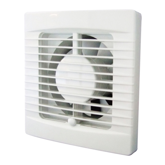
FAN0072/0075/0080 Wall Fan and Kits
(The 'new' ball bearing designed motors provide an extended lifetime of operation)
NOTE: (i) The fan is to be installed so that the blades are 2.1m above the floor. For best results
this Extractor Fan should be fitted as high on the wall as possible, or if preferred, on
the ceiling.
(ii) Do not install the unit within a shower cubicle. Use our shower fan models no's
SF125S or SF125T.
(iii) Switch off mains supply before making electrical connections. This system should
be installed by a qualified electrician.
(iv) This fan is double insulated and does not require an earth.
(v) When installing fan through an external wall, an external wall grille must be fitted
at all times.
1.
Cut a 140mm diameter hole in the wall. If the fan is to be fixed onto the ceiling ensure that
the hole is between the joists.
2.
Fit 125mm ducting flush to the plaster.
3.
Remove the cover from the fan by simply unclipping the fascia. The front cover screw and
plug are conveniently located within the fan housing as shown in diagram 1 & 2.
4.
Hold the body of the fan against the wall or ceiling and mark the four screw holes and the
cable entry.
IMPORTANT: Ensure that the fan is square on wall the or ceiling.
5.
Bring power cable into position, as marked. Allow an extra 230mm (9") protruding to
facilitate connection.
Fan should only be installed by fixed wiring, a flexible cord should not be used.
6.
If an XP125 kit - Select a suitable position on the outside wall for the weatherproof cowl.
Carefully remove the cowl from its housing by levering gently at the sides with a small
screwdriver. Cut a 140mm hole ensuring first that the area is free from obstruction.
7.
Wiring of Standard Model (see Diagram 2A).
(For remote switch operation).
The fan can be connected to the light switch so that the fan will start when the light is switched
on. The fan should not be accessible to a person using either the shower or the bath.
NOTE: All wiring must be fixed securely and the cable to the fan should be a minimum of
1mm
2
in section. All wiring must comply with current Regulations. This system should be
installed by a qualified electrician.
C L A S S I C S E R I E S
Advertisement

Related Manuals for Manrose Classic Series


Summary of Contents for Manrose Classic Series
- Page 1 Carefully remove the cowl from its housing by levering gently at the sides with a small screwdriver. Cut a 140mm hole ensuring first that the area is free from obstruction. We reserve the right to change specification without prior warning Wiring of Standard Model (see Diagram 2A). (For remote switch operation). Manrose is proudly distributed by Ventair Pty Ltd The fan can be connected to the light switch so that the fan will start when the light is switched 4 Capital Place, Carrum Downs, 3201 VIC, AUSTRALIA. on. The fan should not be accessible to a person using either the shower or the bath. Technical Support (03) 9775 0556 NOTE: All wiring must be fixed securely and the cable to the fan should be a minimum of e: info@ventair.com.au | www.ventair.com.au | www.manrose.com.au...
- Page 2 Wiring of Pullcord Models (see Diagram 1). Diagram 1 (This model is unsuitable for ceiling mounting). This fan has its own integral pullcord on/off switch. The fan should not be accessible to a person using either the shower or the bath. NOTE: All wiring must be fixed securely and the cable to the fan should be a minimum of 1mm in section. All wiring must comply with current Regulations. This system should be installed by a qualified electrician. IMPORTANT Wiring of Timer Model See Diagram 2 & 2A. The fan can be connected to the light switch so that the fan will start when the light is FAN MUST BE INSTALLED THIS switched on. When the light switch or pullcord is switched off the fan will run for between WAY UP WHEN 20 sec & 30 minutes (pre-set to 1 minute). The fan should not be accessible to a person...
Need help?
Do you have a question about the Classic Series and is the answer not in the manual?
Questions and answers