
Related Manuals for KanexPro EXT-PROCTRL


Summary of Contents for KanexPro EXT-PROCTRL
- Page 1 Flexible Matrix System Controller powered by SDVoE w/ POE & RS-232 All Right Reserved MPN: EXT-PROCTRL VER 1.0...
- Page 2 SAFETY PRECAUTIONS Please read all instructions before attempting to unpack, install or operate this equipment and before connecting the power supply. Please keep the following in mind as you unpack and install this equipment: • Always follow basic safety precautions to reduce the risk of fire, •...
-
Page 3: Table Of Contents
CONTENTS 1. Introduction……………………………………………..…………………………………………………….....……………………….1 2. Applications……………………………………………………..………………………………………………....…………………….…1 3. Package Contents……………………………………………………………………………………….....…………………………..2 4. System Requirements………………………………………………………………………………….....…………………………2 5. Features………………………………………………………………………………………………………….....…………………………..2 6. Operation Controls and Functions…………………………………………………………....……………………….3 Front Panel………………………………..………………………………………………………………………………………….….3 Rear Panel……………………………………..……………………………………………………………………………………….…3 Remote Control………………………………...…………………………………………………………………………..………..4 IR Cable Pinouts………………………………..………………………………………………………………………………….…5 RS-232 Pinout and Defaults……………………………………………………………………………………………..5 WebGUI Control…………………………………………………………………………………………………...…………………6 6.6.1 Monitor & Control Tab…………………………………………………………………………………………...…………..8 6.6.2 System Tab…………….…………………………………………………………………………………………………..21 6.6.3 Settings Tab………….……………………………………………………………………………………………….….24 6.6.4 Transmitter Tab………..………………………………………………………………………………………………35 6.6.5 Receiver Tab……………….………………………………………………………………………………………….…39... -
Page 4: Introduction
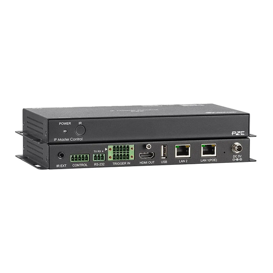
Add the system to a 10G network and enjoy UHD 4K Lossless video with zero latency. The KanexPro Modular Matrix Controller (EXT-PROCTRL) is a powerful and flexible tool for controlling multiple SDVoE (Software Defined Video over Ethernet) based extender transceivers within same network. -
Page 5: System Requirements
4. SYSTEM REQUIREMENTS • An active network connection from a switch or router for control of compatible AV over IP devices. 5. FEATURES • Enables the management and configuration of multiple compatible SDVoE extenders through a single WebGUI • Provides control over the independent routing of video, audio and control signals between all local compatible transmitters and receivers •... -
Page 6: Remote Control
(OPTIONAL) or any device with trigger switch functionality such as window security alarms, motion detectors, door switches, etc. Each of the 8 trigger inputs will activate the associated macro (1~8) when triggered. Note: A minimum of 5V DC is required to activate each trigger. 5. -
Page 7: Ir Cable Pinouts
6.4 IR Cable Pinouts 6.5 RS-232 Pinout and Defaults 6.6 WebGUI Control • Device Discovery Please obtain the “Device Discovery” software from your authorized dealer and save it in a directory where you can easily find it. Connect the unit and your PC/Laptop to the same active network and execute the “Device Discovery”... - Page 8 1. IP Mode: If you choose, you can alter the static IP network settings for the device, or switch the unit into DHCP mode to automatically obtain proper network settings from a local DHCP server. To switch to DHCP mode, please select DHCP from the IP mode drop-down, then click “Save”...
-
Page 9: Monitor & Control Tab
6.6.1 Monitor & Control Tab This tab provides easy to use drag-and-drop control over all basic routing functionality of the transmitters and receivers that have been detected within the local network. In all sections, except for the Video section, transmitters are represented by the source icon ) and receivers are represented by the display icon ( ). - Page 10 • Source to Single Receiver Routing: To route a source to a receiver, click and drag the source’s button on the left to the preferred display on the right side, then release the mouse button. If the routing was completed successfully, the newly routed source’s name will appear below the display’s name within the button.
- Page 11 1. Video Wall Routing: Provides drag-and-drop source selection for pre-defined video wall groups. Note: Video wall groups are defined within the Video Wall tab, please see section 6.6.7 for more information.
- Page 12 • Group: All currently defined video wall groups will be listed under the “Group” heading. Clicking on a group’s icon will display a simplified graphical representation of the video wall on the right side of the page in the Group View. •...
- Page 13 display a faded video thumbnail of each window’s currently selected source. • Transmitter: All sources are listed here with any currently unavailable sources displayed in red. To assign a new source to an existing Multiview layout’s window, drag the source to the preferred window within the Multiviewer View. Note: A single source cannot be simultaneously displayed in differently sized windows or in multiple presets at different output resolutions.
- Page 14 • Source to Multiple Receiver Routing: To route an HDMI audio source to multiple receivers at the same time, click and drag the source’s button on the left to a Group button or the “All” button on the right side, then release the mouse button. If the routing was completed successfully, the source’s name will appear within all appropriate buttons.
- Page 15 4. Analog Audio Routing: Provides drag-and-drop control over the routing of analog audio input streams between all detected transmitters and receivers. • Analog Audio Transmitter: This section provides drag-and-drop buttons for all analog input sources detected by the system as well as a button target to stop one or all analog audio streams from being transmitted.
- Page 16 Downmix)” that output will be marked with a (!) and the audio output will mirror the source set on the HDMI Audio routing page. • Stop Stream: To stop the analog audio output on a single receiver, drag the receiver down to the “Stop”...
- Page 17 • Stop Host: To stop communication from a USB host, drag the USB host down to the “Stop” button at the bottom of the window, then release the mouse button. • USB Device: This section provides drag-and-drop buttons for all detected USB device endpoints as well as a button target to stop communication from a device.
- Page 18 • IR Output to IR Input Routing: To connect an IR output to an IR input, click and drag the IR output’s button on the right to the preferred IR input on the left side, then release the mouse button. If the routing was completed successfully, the newly routed IR output’s name will appear below the IR input’s name within its button.
- Page 19 • RS-232 Receiver: This section provides drag-and-drop buttons for all RS-232 receivers detected by the system. • RS-232 Receiver to RS-232 Sender Routing: To connect an RS-232 receiver to an RS- 232 sender, click and drag the RS-232 receiver’s button on the right to the preferred RS- 232 sender on the left side, then release the mouse button.
-
Page 20: System Tab
6.6.2 System Tab This tab provides access to system configuration options including IP configuration for both LAN ports, interface language, login and user management, and firmware update functionality. 1. LAN 1 & LAN 2: The IP mode for each LAN port (DHCP or Static IP), IP address, netmask, and gateway can be set here. - Page 21 *.bin file. Click the “Choose File” button to locate the saved *.bin file, then click the “Open” button. • Save Log: A comprehensive system log file to help diagnose configuration issues or other problems can be generated, if requested by technical support. Click the “Save Log”...
-
Page 22: Settings Tab
6.6.3 Settings Tab This tab provides control over the configuration of a variety of the unit’s different internal systems and interfaces including group and macro creation, manual IR and RS- 232 command broadcasting, I/O trigger assignment, EDID management, and setting the system’s clock and event scheduling. - Page 23 • Group List: This section contains all of the receiving endpoints that are assigned to the currently selected group. Clicking on an endpoint will remove it from the group and place it back in the “Device” section. To remove all devices from the current group, click on the “Remove All”...
- Page 24 • Order: Use the dropdown to select the position within the macro list for the currently selected macro. Note: The order in the list also impacts the order macros are listed within the Monitor & Control tab and when assigning IR/trigger functionality. •...
- Page 25 3. RS232/IR: This section provides a way to manually send individual RS- 232 or IR commands to specific receiver endpoints within the current system. • RS-232: To send an RS-232 command, use the dropdown to select the target endpoint, type or paste the command into the space provided, and then click “Send” to transmit the command immediately.
- Page 26 5. EDID: This section provides a way to manage and assign EDID to any or all of the available transmitters. EDIDs may be assigned from a selection of 6 built in default EDIDs, the displays connected to any receiver, or from a user uploaded EDID. •...
- Page 27 This unit provides the following 6 default EDIDs: Note: In some rare cases it is possible for custom or external EDIDs to cause compatibility issues with certain sources. If this happens, it is recommended to switch to one of the 7 default EDIDs for maximum compatibility.
- Page 28 6. Time: This section provides a way to automatically set and sync the unit’s system clock using a standard internet NTP (Network Time Protocol) server. • NTP Server: Enter the hostname or IP address of the preferred NTP server to use for time synchronization.
- Page 29 Note: Leaving this screen before selecting “Save Schedule” will undo any changes made. • Schedule Name: Enter the preferred name for the current schedule event. • Activate: Use the dropdown to enable or disable the current schedule event. • Macro: Use the dropdown to select the macro to activate at the scheduled time. •...
- Page 30 Activate Date: The activate date is the date and time of the first execution of the macro. Clicking on the date field will open the calendar entry window. Select the preferred day and time and then click “Done”. Clicking the “Now” button will jump the entry field to the current time.
-
Page 31: Transmitter Tab
Time: Enter the time to execute the macro on all selected days. Clicking on the time field will open the “Choose Time” window to make setting a time easier. • Save Schedule: Click this button to save changes to the current schedule. 6.6.4 Transmitter Tab This tab shows all transmitters that have been detected by the unit. - Page 32 • Icon: Displays the icon used to represent the unit. Note: If a transmitter’s streams require more bandwidth than is available, a warning icon ( ) will be displayed instead of the normal source icon. Video output from a source displaying this icon may become visually unstable.
- Page 33 • System Command: Use the dropdown to select a system command to send to the unit. Typically available commands are: - Factory Reset: Reset the unit back to its factory default settings. - Reboot: Reboot the unit. - Firmware Update: Update the firmware of this unit using the currently uploaded firmware file.
-
Page 34: Receiver Tab
6.6.5 Receiver Tab This tab shows all receivers that have been detected by the unit. Details about each receiver’s name, IP address, and video content, as well as options to configure the network, RS-232, USB and general device settings are also provided. Note: Units that were previously a part of the system, but are not currently detected will still be displayed, however they will have a disconnected icon ( ) and cannot be used for routing. - Page 35 • IP Address: Displays each unit’s current IP address. • Video Info: Clicking this button will display a pop-up window containing detailed information about the current video output. Note: If no display is detected the button will turn red. • Network Settings: Clicking this button will display a pop-up window containing detailed information about the unit’s current network settings, including IP mode, and allow for those settings to be changed.
- Page 36 • System Command: Use the dropdown to select a system command to send to the unit. Typically available commands are: - Factory Reset: Reset the unit back to its factory default settings. - Reboot: Reboot the unit. - Firmware Update: Update the firmware of this unit using the currently uploaded firmware file.
-
Page 37: Scaling Tab
Note: Selecting this will automatically change the Analog Audio Source type to “HDMI Audio (Stereo Downmix)”. This setting overrides any manual routing selections made from the Analog Audio routing tab. - Follow Tx Analog Audio: The analog audio output will automatically use the analog input on the currently routed HDMI video’s transmitter. -
Page 38: Video Wall Tab
6.6.7 Video Wall Tab This tab provides a way to configure or modify video walls using multiple receivers in a group. All aspects of the video wall group can be configured here including dimensions (up to 8x8 displays), bezel compensation, display output resolution, and source. 1. -
Page 39: Multiview Tab
necessary. Selecting “Full Screen” will stretch the source to fit the video wall, regardless of the original source’s aspect ratio. • Wall Size: Select the size of the video wall, measured in number of monitors tall by number of monitors wide. The maximum number of displays in a single video wall is 64 (8x8). •... - Page 40 1. Multiview Preset List: The upper left section of this tab contains a list of all currently defined multiview presets in the system and provides a way to create new presets, edit them, or delete them. To add a new preset, click on the “Add” icon ( ) and then select the preferred options and window configuration.
-
Page 41: Telnet Control
• Multiview Layout Selection: This a scrollable list of premade multiviewer layout designs. Click on the design that best matches your preferred layout and source count requirements to place it in the layout window to the right. Note: Customized layouts are not currently supported. •... -
Page 42: Rs-232 And Telnet Commands
6.8 RS-232 and Telnet Commands... - Page 51 Note: Commands will not be executed unless followed by a carriage return. Commands are not case-sensitive.
-
Page 52: Connection Diagram
HDMI Cable LAN Cable Extend up to 120 meters (495 feet) over CAT6a Encoder Mode Decoder Mode Keyboard Mouse Sources Displays EXT-PROCTRL Projector NETWORK SWITCH 10G POE NETWORK SWITCH EXT-PROCTRL EXT-PROMATRIXE XT-PROMATRIX x1 RX in this case x9 RX in this case... -
Page 53: Specifications
8. SPECIFICATIONS 8.1 Technical Specifications HDMI Output Resolution: 1920x1080@60Hz Output Ports: 1xHDMI (Type-A) 1xRS-232 (5-pin Terminal Block) Control Ports: 1xIR Extender (3.5mm) 1xRS-232 (3-pin Terminal Block) 8xTrigger (10-pin Terminal Block) 2xLAN (RJ-45) 1xUSB 2.0 (Type A) IR Frequency: 38kHz Baud Rate: 19200 Power Supply: 5V/2.6A DC... -
Page 54: Video Specifications
8.2 Video Specifications... -
Page 55: Cable Specifications
8.3 Cable Specifications Bandwidth Category Examples: • 1080p (FHD Video) - Up to 1080p@60Hz, 12-bit color - Data rates lower than 5.3Gbps or below 225MHz TMDS clock • 4K30 (4K UHD Video) - 4K@24/25/30Hz & 4K@50/60Hz (4:2:0), 8-bit color - Data rates higher than 5.3Gbps or above 225MHz TMDS clock but below 10.2Gbps •... -
Page 56: Acronyms
9. ACRONYMS... - Page 57 Remarks: For further assistance or solutions, please contact your local distributor, or email directly to us at support@kanexpro.com...
Need help?
Do you have a question about the EXT-PROCTRL and is the answer not in the manual?
Questions and answers