
Related Manuals for Nexen AIR CHAMP FMCE Series


Summary of Contents for Nexen AIR CHAMP FMCE Series
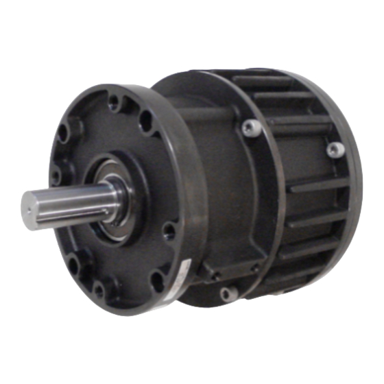
- Page 1 FMCE FLANGE MOUNTED CLUTCH WITH ELECTRONIC SLIP DETECTOR MODELS 625, 875, AND 1375 FORM NO. L-20318-E-1112...
- Page 2 In accordance with Nexen’s established policy of constant product improvement, the specifications contained in this manual are subject to change without notice. Technical data listed in this manual are based on the latest information available at the time of printing and are also subject to change without notice.
-
Page 3: Table Of Contents
Table of Contents Installation ----------------------------------------------------------------------------------------------------------------------------------------- 3 Air Connections ---------------------------------------------------------------------------------------------------------------------------------6 Lubrication -----------------------------------------------------------------------------------------------------------------------------------------6 Electrical Connections ------------------------------------------------------------------------------------------------------------------------7 Troubleshooting -------------------------------------------------------------------------------------------------------------------------------8 Parts Replacement – Friction Facing (All Models) ---------------------------------------------------------------------------------9 Parts Replacement – Sensors(All Models) ------------------------------------------------------------------------------------------10 Parts Replacement – Housing Bearing, Model FMCE 625 ------------------------------------------------------------------11 Parts Replacement – Female Pilot Bearing, Models FMCE 875, 1125 and 1375------------------------------------12 Parts Replacement –... -
Page 4: Installation
INSTALLATION FMCE 625 MOUNTED ON THE SHAFT END OF A MOTOR NOTE Align the Solenoid Valve, located on the Plug Set Screw FMCE, to a down position to allow condensa- (Item 27) (Item 26) tion to drain out of the air chamber Customer supplied key CAUTION Use caution not to bump or damage the... - Page 5 FMCE 625 MOUNTED BETWEEN A GEAR REDUCER AND A MOTOR NOTE Align the Solenoid Valve, located on the Customer supplied FMCE, to a down position to allow condensa- socket head cap screws, tion to drain out of the air chamber lock washers, and nuts Plug (Item 27)
-
Page 6: Air Connections
Synthetic lubricants are not recommended. LUBRICATOR DRIP RATE SETTINGS NOTE These settings are for Nexen supplied lubricators. If you are not using a Nexen lubricator, calibration must replicate the following procedure. Connect the air line to the unit. Close and disconnect the air line from the unit. -
Page 7: Electrical Connections
ELECTRICAL CONNECTIONS CAUTION Solenoid Use caution not to bump or damage the Valve Sensors during assembly or disassembly. Connector (Item 30) Connect the Red and Black leads from the Connector (Item Connector 30), located on the Solenoid Valve, to Terminals 5 and 6 of (Item 33) the Connector (Item 33) by pushing a screwdriver into the slot on the top of the Connector and then inserting the Red... -
Page 8: Troubleshooting
TROUBLESHOOTING Input Output Sensor Sensor Solenoid O-ring Connector Splined Chamber Valve Seals Disc Housing Male Pilot Dowel Drive Ball Disc Bearings Stub Ball Shaft Bearings Piston Compression Friction Spring FIGURE 8 Facing Typical FMCE n i t h t i f l a i t c p i l... -
Page 9: Parts Replacement - Friction Facing (All Models)
PARTS REPLACEMENT - FRICTION FACING (ALL MODELS) CAUTION Socket Head Cap Screw Use caution not to bump or damage the (Item 12) Sensors during assembly or disassembly. Friction Facing (Item 8) 1. Disconnect the Red and Black leads from the Connector (Item 30), located on the Solenoid Valve, from Terminals 5 Flat Head and 6 of the Connector (Item 33) by pushing a screwdriver... -
Page 10: Parts Replacement - Sensors(All Models)
PARTS REPLACEMENT - SENSORS (ALL MODELS) CAUTION Socket Head Use caution not to bump or damage the Cap Screws Sensors during assembly or disassembly. (Item 12) Disconnect the Red and Black leads from the Connector Housing (Item 30), located on the Solenoid Valve, from Terminals 5 (Item 1) Solenoid and 6 of the Connector (Item 33) by pushing a screwdriver... -
Page 11: Parts Replacement - Housing Bearing, Model Fmce 625
PARTS REPLACEMENT - HOUSING BEARING, MODEL FMCE 625 CAUTION Use caution not to bump or damage the Sensors during assembly or disassembly. NOTE If an Input Unit is installed on the FMCE, it must be removed before servicing the FMCE. Remove the Plug (Item 27) and loosen the Set Solenoid Screw (Item 26) to release the FMCE from the... -
Page 12: Parts Replacement - Female Pilot Bearing, Models Fmce 875, 1125 And 1375
PARTS REPLACEMENT - FEMALE PILOT BEARING, MODEL FMCE 875, 1125 AND 1375 CAUTION Use caution not to bump or damage the 12/24 Female Pilot Sensors during assembly or disassembly. (Item 13) NOTE If an Input Unit is installed on the FMCE, it must be removed before servicing the FMCE. -
Page 13: Parts Replacement - Bearings And O-Ring Seals (All Models)
PARTS REPLACEMENT - BEARINGS AND O-RING SEALS (ALL MODELS) CAUTION Use caution not to bump or damage the Sensors during assembly or disassembly. Disconnect the Red and Black leads from the Connector (Item 30), located on the Solenoid Valve, from Terminals 5 and 6 of the Connector (Item 33) by pushing a screwdriver into the slot on the top of the Connector;... - Page 14 15. Apply an adequate amount of Loctite 680 to evenly coat 32. Press the second new Bearing (Item 18) onto the Stub Shaft ® the outer race of the new Bearing (Item 2). (Item 22) (See Figure 16). 33. Apply an adequate amount of Loctite 680 to evenly coat 16.
-
Page 15: Parts Replacement - Input Unit
Ball Bearing is seated against the Retaining Ring (Item 58) (See Figure 17). PARTS REPLACEMENT The item or balloon number for all Nexen products is used for part When ordering replacement parts, specify model designation, identification on all product parts lists, product price lists, unit item number, part description, and quantity. -
Page 16: Parts List - Fmce 625 With Electronic Slip Detector
PARTS LIST FMCE 625 WITH ELECTRONIC SLIP DETECTOR 33/35 FIGURE 18 ITEM DESCRIPTION ITEM DESCRIPTION Housing Male Pilot Bearing O-ring Seal Retaining Ring (Int.) O-ring Seal Drive Disc Stub Shaft Retaining Ring (Int.) Retaining Ring (Ext.) Retaining Ring (Ext.) Key (Not Shown) Flat Head Screw Set Screw Friction Facing... -
Page 17: Parts List - Fmce 875 With Electronic Slip Detector
FMCE 875 WITH ELECTRONIC SLIP DETECTOR 33/35 FIGURE 19 ITEM DESCRIPTION ITEM DESCRIPTION Male Pilot Housing Bearing O-ring Seal O-ring Seal Retaining Ring (Int.) Drive Disc Stub Shaft Retaining Ring (Ext.) Retaining Ring (Int.) Retaining Ring (Ext.) Socket Head Cap Screw Key (Not Shown) Flat Head Screw Friction Facing... -
Page 18: Parts List - Fmce 1125 With Electronic Slip Detector
FMCE 1125 WITH ELECTRONIC SLIP DETECTOR 33/35 FIGURE 20 ITEM DESCRIPTION ITEM DESCRIPTION Housing Male Pilot Bearing O-ring Seal Retaining Ring (Int.) O-ring Seal Drive Disc Stub Shaft Retaining Ring (Int.) Retaining Ring (Ext.) Retaining Ring (Ext.) Socket Head Cap Screw Flat Head Screw Key (Not Shown) Friction Facing... -
Page 19: Parts List - Fmce 1325 With Electronic Slip Detector
FMCE 1375 WITH ELECTRONIC SLIP DETECTOR 33/35 FIGURE 21 ITEM DESCRIPTION ITEM DESCRIPTION Housing Male Pilot Bearing O-ring Seal Retaining Ring (Int.) O-ring Seal Drive Disc Stub Shaft Retaining Ring (Int.) Retaining Ring (Ext.) Retaining Ring (Ext.) Socket Head Cap Screw Flat Head Screw Key (Not Shown) Friction Facing... -
Page 20: Parts List - Input Unit
PARTS LIST - INPUT UNIT ITEM DESCRIPTION Stub Shaft Bearing Flange Ball Bearing Retaining Ring Hex. Head Jam Nut (Not Shown) Retaining Ring FIGURE 22 FORM NO. L-20318-E-1112... -
Page 21: Warranty
Buyer shall be obligated to pay or which Buyer may incur based upon, related to or arising out of its contracts with its customers or other third parties. In no event shall Nexen be liable for any amount of damages in excess of amounts paid by Buyer for Products or services as to which a breach of contract has been determined to exist.
Need help?
Do you have a question about the AIR CHAMP FMCE Series and is the answer not in the manual?
Questions and answers