
Related Manuals for Sommerkamp TS-727GT


Summary of Contents for Sommerkamp TS-727GT
- Page 1 CITIZENS BAND TRANSCEIVER INSTRUCTION MANUAL MODEL: TS-727GT FTZ APPROVAL NO. К16Э/7А MDDELTS-737...
- Page 2 SOMMERKAMP ELECTRONIC SAS CH- 6 9 0 3 LUGANO, RQ BOX 106 SWITZERLAND TEL. 91 6 99 54 3 TELEX'-Z9314...
-
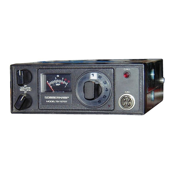
Page 3: Control Locations
SOUELCH KNOB' "S"M£TER RECEIVING LIGHT CHANNEL SELECTOR KNOB- MICROPHONE JACK TRANSMITT1NG LIGHT PACKING LIST: Beside this manuał, the carton shall contain the foiiowing items: 1 Transceiver TS-727GT 1 Mounting bracket 4 Screw for Mounting bracket 1 Microphon hanger 1 Microphone —... -
Page 4: General Description
GENERAL DESCRIPTION Your SOMMERKAMP TS-727GT transceiver has been designed for continous heavy duty mobile and base station application. It can be operated with a microphone and internai speaker or headset, speaker/ microphone combination, telephoneset incorporating automatic voice operated transmit/receive switching, external sélective calling with automatic answerback and many more. -
Page 5: Receive/Transmit Switching
TRANSMITTER & MODULATOR SECTION: The transmitter section is designed for continous heavy duty transmission amplitude modulated (AM/A3) signais in the 26.965 to 27.275 MHz. (11 meter) citizens band. The transm itter consists of crystal controlled oscillator. The output of this oscillator is followed by a tuned filte r, and a highly efficient collector-modulated dass C driver and power output stage, coupled by séries and pi-matching filters to the antenna jack. - Page 6 Connect the antenna pług to the antenna jack with an SWR-Meter inserted into the antenna cable. Connect the microphone to the microphone jack. Switch the transceiver ON. The receiving, meter and the channel lamp shall iight up. Turn the Squelch control to min. (ANL OFF) Turn the Volume control to max.
- Page 7 0PERAT1NG INSTRUCTIONS The transceiver is ready to operate when it is instailed with an antenna properly connected. Note that the communication range differs depending upon the environ ment where the transceiver is operated. You may reach 30 or 40 kilometers where no obstacle exists, but the range may be limited to 5 or 6 kilometers in cities where many high buildings disturb the communication.
-
Page 8: Microphone Jack
MICROPHONE JACK The 7-pin DIN standard accessory jack has the following internai connections: 1. Microphone input(Z 600-10K ohm) 5. Audio output (Z 8 ohm-10K ohm) 2. Transmit/Receive switching. 6. 4 -12V for VOX unit etc. 3. Internai microphone output(Z 1K ohm) 7. Ground return for 1-6. 4. - Page 9 SCHEMATIC DIAGRAM...
- Page 10 CRYSTAL INSTALLATION Remove the unit from its mount, disconnect the power lead and antenna cable at the rear of the unit. 2. Remove two screws of the back side of the cabinet. Carefully disassembled the cabinet. Remove speaker leads form the P . C. board. 3.
- Page 11 PRINTED CIRCUIT BOARD PARTS LAYOUT (SOLDERED SIDE)
- Page 12 PARTS & WIRING LAYOUT (COMPONENT SlDE) 12 —...
- Page 13 PARTS LIST for TS -727G T PARTS NO. DESIGNATION PARTS NAME 482009-2 MPI 2 1 Chassis Frame 484081 Back Pannel MP102 504267 Mounting Bracket for P . C. B. (L) MPI 22 504266 Mounting Bracket for P . C. B. (R) MPI 23 483016 Cabinet Cover (Upper)
- Page 14 PARTS LIST for TS -727G T PARTS NO. PARTS NAME DESIGNATION 2SC1739 (P) Transistor TR2, 3, 4 2SC1739 (Q) Transistor TR5, 6, 10 Transistor 2SC1741 (P) 2SC1678 Transistor 2SC496 (0) Transistor 2SC496 (Y) TR12 Transistor Transistor 2SB435 TR11 WZ-090 Zener Diode D14, 15 1S1555 Silicon Diode...
- Page 15 SPECIFICATION for T S -727G T (TS -737) Semiconductors 2 IC, 12 transistor, 15 diode. Transm itter System Triple stage, crystai controlied, Collector modulation AM. 6 channels on 27 MHz. Frequency Frequency Tolérance Within 0.005% ( - 1 0 C to 50°C). 0.5 watts (3 watts).
- Page 16 SOMMERKAMP ELECTRONIC SAS CH - 6903 LUGANO, BOX 176 TELEFON (0041) 91 - 68 85 43 TELEX: (0045) 79314...
- Page 17 Ei FR ECH FU ПН 2У MHz - Sendeempfängen fü r Mobil - und Feststationsbetrieb Modell TS 7 2 7 G FTZ « ZugeSasseo Modell TS 7 3 7...
- Page 18 ALLGEMEINES Ihr SOMMERKAMP TS 727 GT Sendeempfänger ist ein in Kompaktbauweise hergestell- etes Hochleistungs- Funkgerät, ausgeiegt für den Gegensprechverkehr auf 6 ver schieden Kanälen im 27 MHz Citizen Band. Er ist das Ergebnis eingehender Entwicklungsarbeiten unseres Teams erfahrener Konstrukteure.Das gesamte Gerät wurde vom Hersteller sorgfältig abgestimmt und geprüft.
- Page 19 HANDMIKROFONE Ein Mikrofon- Aufhängewinkel mit zugehörigem Montagematerial ist im Lieferum - fang enthalten. Ein sog. "press-to-talk"- Schalter, d.h. Schalter drücken gleichzeitig sprechen, ist am Mikrofon angebracht um Ihnen den Funksprechver - kehr während des Fahrens zu erleichtern. FAHRZEUG- EINBAU Der vorliegende Sendeempfänger ist für einen Fahrzeugeinbau konstruiert , ' bei welchem Batterie Plus (+} an das Geräte Plus {+) gelegt wird.Sollte jedoch das G erät einmal in Fahrzeugen...
- Page 20 BETRIEBSANWEISUNG 1. Drehen sie den AUS/EIN- Lautstärkeregler nach rechts. Das Gerät ist einge schaltet, wenn die Kontrollampe links vom Kanalwahl Knopf aufleuchtet. Die Lautstärke kann mit gleichem Knopf eingestellt werden. 2. Die Rauschsperre dient dazu, störendes Hintergrundgeräusch zu unterdrücken und sollte nur eingestellt werden, wenn keine Sendungen anderer Stationen empfangen werden.
- Page 21 5. Wenn alle Quarze eingesetzt'sind, wird das Gerät wieder in umgekehrter Rei henfolge zusammengesetzt. Alle Gehäuseschrauben fest anziehen. Antennenka - bei und Stromzuführung werden wieder verbunden. Das Gerät ist jetzt bereit zum Einsatz. Achtung - Auf den Kanälen, für welche keine Quarze eingesetzt wurden, darf nicht gesendet werden.
- Page 22 — —...
- Page 24 и — С П •с г а С | о г а >. р г а с СЛ р •н р о р ■ v 3 р с •н С "О а С •н о О и дс о ■н р...
- Page 25 CHANNEL SW. X T A L ( RX XTAL(TX) Г Г ^ J3 -TR9 •POS.CONV. '— ТР1 - - 8 —...
- Page 26 EINZELTEIL- LISTE FÜR TS 727 G T UND TS 727 G Transistoren 2 SC 710 TR4, TR5 TR1, TR2, TR3, 2 SC 712 TR6, TR8, TR9 2 SB 54 2 SC 1096 TR10, TR11 2 SC 774 TR1 2 2 SC 775 TR1 3 2 SC 778 TRI 4...
- Page 27 Potentiometer 10 К Ohm variable 50 К Ohm variable 1 К trimmer Kondensatoren 18pF 22pF 39pF 50pF C23, , C61 lOOpF C22 j , C48, 055, C59 1 50pF C60,, C63 200pF 390pF 510pF C9, C12, 054 0.001UF C31, , C80 O.OOSuF 02,03,04, 05,010,014,017,026,050, 0.01uF...
- Page 28 EINZELTEILÜSTE TS 727 G, TS 727 G T, TS 737 Einzelteil No. Benennung Abkürzung 472002 Chassis-Rahmen 474035 Chassis- Rahmen (vorn) MP 2 473008 Gehäusedeckel (oben) 473009 Gehäusedeckel (unten) 474038 Montagewinkel für Lautsprecher MP 5 474037 Montagewinkel für Trimmer MP 6 474039 Montagewinkel für Lampenlinse MP 7...
- Page 29 Abkürzung Benennung Einzelteil No. TC 1001 Filter- Drossel Drosselspule, Miniatur, 1 uH L 2001 L 2022 L 4, 5 Drosselspule, Miniatur, 2.2 uH L 10 30 HF- Drossel L 1031 HF- Spule L 1032 HF- Spule L 1033 HF- Spule L 1034 HF- Filterspule 177-S 2D/10 KA...
- Page 30 TECHNISCHE DATEN DES TS 727 GT (TS 737) Anzahl der verwendeten Halbleiter : 14 Transistoren, 7 Dioden Senderschaltung Dreistufig, Quarzgesteuert, Kollektormodulation AM Frequenzbereich 6 Kanäle im 27 MHz- Band Frequenztoleranz 0.005 % (-10* C bis 4 - 50° C) 2 Watt (5 Watt) Gesamt- Eingangsleistung Bandbreite maximal 8 KHz...
Need help?
Do you have a question about the TS-727GT and is the answer not in the manual?
Questions and answers