Table of Contents
Advertisement
Advertisement
Table of Contents

Related Manuals for Sommerkamp TS-664S


Summary of Contents for Sommerkamp TS-664S
- Page 1 CITIZENS BAND TRANSCEIVER INSTRUCTION MANUAL MODEL.: TS-664S...
- Page 2 Dynamic type with press-talk switch. Impédance 500 ohm. Speaker: Dynamic type, Voice coil Impédance 8 ohm. Size: 156X58X205 mm. Weight: 2.3 kg. Accessories: Mounting b Mounting hardware, power cord. SOMMERKAMP ELECTRONIC SAS СН-БЭОЗ LUGANO, RO. BOX 17Б . SWITZERLAND TEL. 91 080543 TELEX: 79314...
-
Page 3: Control Locations
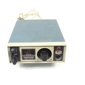
CALL BUTTON -MICROPHONE JACK (CALL CIRCUIT OPTION) CHANNEL SELECTOR KNOB -TRANSM1TT1NG LIGHT PACKING LIST Beside this manuał, the carton shall contain the following items: 1. Transceiver TS-664S. 1. Mounting bracket. 4. Screw for Mounting bracket. 1. Microphone hanger. 1. Microphone. -
Page 4: General Description
GENERAL DESCRIPTION Your SOMMERKAMP TS-664S transceiver has been désignée! for continous heavy duty mobile and base station application. It сап be operated with a microphone and internal speaker or handset, speaker/ microphone combination, telephoneset incorporating automatic voice operated transm it/receive switching, external sélective calling with automatic answer... -
Page 5: Receive/Transm It Switching
TRANSMITTER MODULATOR SECTION: &. The tra sm itte r section is designed for continous heavy duty transmission of amplitude modulated (AM/A3) signais in the 26.965 to 27.595 MHz. (11 meter) citizens band. The transm itter consists of 2 crystal controlled oscillators incorporating 20 crystals. - Page 6 50 OHM A N T . Connect the antenna pług to the antenfia jack with an SWR-Meter inserted into the antenna cable. Connect the microphone to the microphone jack. Switch the transceiver ON. The receiving, meter and the channei iamp, shali light up. Turn the squeich control to min.
- Page 7 Check that the m eter needle is near the red mark during tra n sm ittin g . Talk into the microphone. The m eter needle shall move a little . Release the trans m it button and sw itch the channel selector to channel 1,2 etc.
- Page 8 COMPLETE PARTS LAYOUT SW-l CHANNEL SELEC TO R Н О ТА frf SW. I 1 —...
- Page 9 О...
- Page 10 PARTS LIST for T S -6 6 4 S DESIGNATION PARTS NAME PARTS N0. MP-201 Front Frarne. 483014-S MP-202В Chassis Frame. 502035 MP-203В Back Pannel. 504327 MP-105 Cabinet Cover (Upper). 483016 Cabinet Cover (Lower). 502034 MP-124 484085 MP-107 Mounting Bracket. 494187-L MP-303 Front Plate (L).
- Page 11 PARTS LIST for T S -6 6 4 S DESIGNATION PARTS NAME PARTS NO. Variable Resistor (Volume) 50K ohm. VR1650KB Variable Resistor (Squelch) 10K ohm. VR1610KBS VR1310KBS Variable Resistor (D. Tune) 10K ohm. Semi Variable Resistor 100K ohm. SVR100KF VR11 Semi Variable Resistor 5K ohm.
- Page 12 PARTS LIST for T S -6 6 4 S DESIGNATION PARTS NAME PARTS NO. ЕР-201 Power Cord with Contact & Fuse holder. W-002 Fuse 5A. F-5A Meter. D33B35R М Speaker. SP-70-8 P L 1 -4 PL-14-80 P ilot lamp 14V-80mA. Channel Selector Rotary Switch.
- Page 13 LIST OF CHANNEL FREQUENCIES CH. N0. LOW CH. (MHz) CH. N0. LOW CH. (MHz) HIGH CH. (MHz) HIGH CH. (MHz) 27.285 27.125 27.445 26.965 27.135 26.975 27.295 • 27.455 27.305 27.145 26.985 27.465 27.155 26.995 27.315 27.475 27.325 27.165 27.485 27.005 27.335 27.175...
- Page 14 o4 is ? a i3 ~ v i- v* 3 S9U stM smvrTY 03 /S24T3-VE l J ? 2413 VÉ /ООК AO i. к — > i----- VJIIZ SK VS W JU Em AD J. MODEL TS-B64S...
-
Page 16: Microphone Jack
MICROPHONE JACK The 7-pin DIN standard accessory jack has the following internai connections: 1. Internai speaker (Z 8 ohm) 5. N/C 2. AF. out for sélective calI. 6. -+T2V for VOX unit etc. 3. Audio output (Z 8 ohm-10K ohm) 7. - Page 17 CIRCUIT DIAGRAM MODEL TS-664S...
- Page 18 PRINTED CIRCUIT BOARD PARTS LAYOUT FUSE HOLDER ; W £ ; SA...
Need help?
Do you have a question about the TS-664S and is the answer not in the manual?
Questions and answers