
Related Manuals for Totem T.R.U.C.K.


Summary of Contents for Totem T.R.U.C.K.
- Page 2 Mechanical parts needed to build this model 171x Bolt M3 8mm Bolt M3 16mm Bolt M3 35mm Bolt M3 6mm Bolt M3 12mm Servo SG-5010 Bolt M4 10mm 177x Nut M3 5.5x5.5 Lock Nut M4 Nut M3 6x10 Lock Nut M3 DC motor distance part Bearing M8 16mm RC Wheels 65mm...
- Page 3 20cm 4-wire (JST PH 2mm) 20cm 2-wire (JST PH 2mm) motor at 18V. Function board 30 - power board. Provides up to 2A currents at 5V for Totem bus. FB30 Has integrated overcurrent DC motor cable Totem Bus cable and short-circuit protection...
- Page 4 Build step-number 16 x Double side fi ller 2-hole 45 Bolt M3 6mm L-Twisted Nut M3 6x10 Beams : 4 x 5cm , 8 x 4cm , 8 x 2cm TIP: Insert the Double Side Filler AFTER one side of the bracket is loosely fi xed.
- Page 5 The blue section shows you what parts you need to build each step. Bolt M3 6mm Nut M3 6x10 Combine the Wheel Arches “A” into 2 Sub-assemblies “B”. In this white rectangle you Whenever you see a “#nn” will fi nd additional guidance character, it means “slot number”...
- Page 6 This rectangle shows the result you have after fi nished building the current step. 2-hole Simple Nut M3 6x10 Bolt M3 6mm L-bracket Beams : 2 x 17 cm The Sub-assembly “C” will This section of a building combine the 2 wheel arch step is the exploded view assemblies “B”...
- Page 7 Here we show how many equal parts to make of this sub- assembly. M3 6mm bolt Nut M3 6x10 Sub-assemblies : 2x B , 1x C We give each sub -assembly a letter, so later we can refer to it when combining with other sub- assemblies.
- Page 8 M3 6mm bolt Brass Standoff M3 8mm Nut M3 6x10 Servo SG-5010 Sub-assemblies: 1x D D + servo It’s time to fi x the servo motor to the car’s frame. It’s enough to use 2 bolts in a diagonal to fi x the servo. Upper slot Start with putting the rectangular...
- Page 9 M3 12mm bolt L-Twisted mirror Lock nut M3 Strip bracket 40mm Sub-assemblies: 1x D + strip bracket 40mm D cont The servo arm with bracket will later be attached to the steering mechanism (Step 18). In this step you will make the servo actuator steering arm.
- Page 10 2-hole Simple M3 6mm bolt Nut M3 6x10 C-Bracket 2-hole 90 Beams : 2x 9cm, 5x 4cm Make 4 pcs: Make 2 pcs: This step is to make the case that houses and fi xes the steering mechanism. First you make 4 “legs”, then connect them with 9cm beams into 2 halves.
- Page 11 Lock nut M4 Bearing Axle M8 16mm Bearing M3 35mm bolt 12mm Hex Wheel Fix Bearing Barrel M3 12mm bolt Making the wheels barrels. Lock nut M3 OBS!: Lock nut M4 OBS: TIP: Many parts are To fasten lock nuts: First enter shown with nuts with fi ngers.
- Page 12 Beam Plug Bolt M3 6mm Nut M3 6x10 C-Bracket M3 8mm bolt Nut M3 6x6 Beams : 2 x 4cm OBS: The orientation and position of The sub assembly “F” is the the beam-plug is vertical steering column. They will important.
- Page 13 2x+2x Bolt M3 6mm Nut M3 6x10 Strip bracket 40mm Beams : 4 x 3cm, 4x strip brackets 40 mm G1 , G2 OBS: Please take care to make these parts correct. Double- check the parts before going to the next step.
- Page 14 1x + 1x Lock nut M3 M3 12mm bolt Sub-assemblies: 2x F , 4x G H1 & H2 OBS: The hole in the OBS: Beam Plug must Take care to be in lower orient the position. G1 and G2 correct. Strip brackets In this step you will combine the in lower...
- Page 15 1x + 1x Lock nut M3 Sub-assemblies: 2x E , 2x H I1 + I2 Find your previously assembled “E” Sub-assemblies, and use lock TIP: nut M3 to attach them to the Use an allen key previous steps “H1” and “H2” parts. for M3 when Tighten the M3 nuts enough so tightening the...
- Page 16 1x + 1x 2-hole Simple Nut M3 6x10 M3 6mm bolt L-Twisted L-Twisted mirror Beams 2x 2cm J1 & J2 Push the brackets all in close to the beams. The part “J1 and “J2” functions as the arms to the steering column. The 2 angled brackets is fi xed in a special way to the beams.
- Page 17 Nut M3 6x10 M3 6mm bolt L-Twisted L-Twisted mirror Beam : 1x 8cm Pull the brackets all out sideways. This part “H” will connect the right and left part of the steering mechanism from previous steps. Note that the adjustable brackets should be fi xed in the “outer”...
- Page 18 Lock nut M3 Distance tower 6mm M3 16mm bolt Sub-assemblies: 1x J1, 1x J2, 1x K This step connects “K” to the 2 OBS: “J” arms. Use 2 distance towers, Note the position length 6mm as shown. Tighten the of the L-twisted lock nuts just enough to get a good brackets! smooth pivot action.
- Page 19 M3 6mm bolt Nut M3 6x10 Sub-assemblies: 1x I1 + 1x I2 + 1x L It’s time to connect the parts from previous steps into the complete Sub-assembly of the movable parts in the steering mechanism. The 2 arms are connected to the vertical beams as shown.
- Page 20 Nut M3 6x10 M3 16mm bolt Sub-assemblies : D + M OBS : Model is seen from the underside ! The upper arms will be fi xed later. Now you will attach the steering mechanism “M” to the frame “D”. Use 16mm M3 bolts going through the 3cm beams in the lower steering part, into the rectangular...
- Page 21 M3 6mm bolt Nut M3 6x10 Sub-assemblies : D + N O-cont. OBS: Tighten two 12mm bolts, and 3mm Lock Nuts after the bracket is fi xed to the steering. Tighten so that motion is smooth, not too tight or loose. Now it is time to attach the steering servo actuator arm to the steering part “M”.
- Page 22 Nut M3 6x10 M3 6mm bolt M3 16mm bolt Sub-assemblies : 1x N + 1x O TIP: Use an Allen A : First put 4 nuts into frame as B : Then put 4 nuts into steering here. shown. part as shown. To fi nish the steering mechanism, you will attach the steering case “N”...
- Page 23 L-Twisted mirror M3 6mm bolt Nut M3 6x10 2-hole simple 3-hole bracket Beams: 2x 12cm, 1x 8cm NOTE: Two L-twisted mirror brackets should be adjusted to the left as the arrows show. You will now continue with the back-wheel frame “Q”. The 3x 3-hole adjustable straight brackets is used to compensate the 45 degree lengths in the wheel...
- Page 24 M3 6mm bolt Nut M3 6x10 2-hole Simple Beams: 1x 2cm, 1x 8cm Q-cont Continue with a mid-section in the back-wheel frame, which have the purpose to strengthen the frame. TIP: 1. Start with all the nuts. 2. Then fi x brackets to assembly. 3.
- Page 25 Nut M3 6x10 M3 6mm bolt Sub-assemblies : P + Q NOTE: Loosen bolts , then adjust after inserting the brackets. Tighten at last. Now, attach the back wheel frame “Q” to the rest of the model “P”. You must probably loosen the bolts on the 3-hole straight brackets, in order to slid them into the back of the frame.
- Page 26 M3 6mm bolt Nut M3 6x10 3 hole bracket 2 hole 90 L-bracket Beam : 1x 7cm These two brackets will be adjusted later. The motor needs a fi xture for later to be attached to the car. Rest of the S-assembly will be done in the next step.
- Page 27 12mm Hex 25mm geared 25mm motor M3 16mm bolt wheel-fi x M3 6mm bolt Lock nut M3 motor Bracket Fixing the motor S assembly. DC motor distance part S-Cont. Preferred orientation of the motor. First attach the distance part (plastic) and the motor bracket with 3x 16mm bolts, with lock nuts M3.
- Page 28 M3 6mm bolt Nut M3 6x10 Sub-assemblies: 1x R + 1x S Attach the motor assembly “S” to the rest of the frame.
- Page 29 Lock nut M3 M3 8mm bolt Beam Plug Nut M3 6x6 Beam : 1x 6 cm + 1x sub-assembly E Use an Allen key (2mm) to help fastening the bolt. The other back-wheel is using a bearing barrel “E” from an earlier assembly step.
- Page 30 M3 6mm bolt Nut M3 6x10 Sub-assemblies T + U Now attach the “U” assembly to the car. The twisted brackets the “U” assembly is received by, can be adjusted so the beam slips easily in. Tighten well.
- Page 31 RC Wheels 65mm M4 10MM Bolt Sub-assembly V V-cont. Use a standard TIP: screw driver Hold the wheels to fasten the with one hand wheel bolts. (The while screwing screwdriver is not them on the car, included in the kit) so they don’t turn.
- Page 32 In this step, the illustrations have shown some corner parts not fully exploded. They are standard Totem joints that you will be more and more familiar with. E.g. C-bracket corners and simple bracket corners.
- Page 33 Nut M3 6x10 Preparation for fi xing sub-assembly W Prepare the frame with 4 nuts (10x6mm) on the underside as shown in the illustration on the right. The nut indicated with be in a tight spot. You may loosen some screws nearby to make it fi t into it’s slot.
- Page 34 M3 6mm bolt Nut M3 6x10 Sub-assembly V + W The frame “W” is attached to the car as shown with 6 bolts and 2 more nuts. The front part is fi xed to 2x 2-hole 90 brackets. Adjust them so they fi t best.
- Page 35 Nut M3 6x10 M3 6mm bolt C-Bracket 3x18650 Li-Ion pack Sub-assembly X cont. X cont. Cables facing backwards. Place one battery stopper on each side of the battery. Now is the time to insert the battery into the car. The red parts shown in the picture to the right shows how to make battery stoppers.
- Page 36 Nylon Standoff 8mm Nut M3 6x10 Electronics boards fi x. This step prepares for the fi xing of the electronics to the model. The supplied 8mm Nylon Standoffs are black.
- Page 37 Nylon Standoff M3 - 7mm M3 6mm bolt Electronics boards mounting step. Electronics modules needed: 1x X3 Baseboard 1x X2 Baseboard 1x Battery connection board BC1 In this step, you will attach 3 electronics boards as shown. The white Nylon Standoffs are 7 mm high.
- Page 38 M3 6mm bolt Electronics boards mounting step 2. FB53 FB30 Electronics modules needed: 1x Power Function Board FB30 1x DCmotor+2ch Servo Board FB53 In this step, the fi nal 2 boards are mounted. Carefully snap the Function Boards 30 and 53 to the corresponding Base BoardsX3 and X2.
- Page 39 3-cell with XT60 Cable. 20 cm 2 connector wire with JST connectors FB30 Battery / 5V Power Cable. 20 cm 4 wire with Totem Bus JST connectors Cable 15cm 6wire fl at-cable, black connectors. DC Motor 25mm DIA with connection board.
-
Page 40: Final Step
Battery cable , fixed to the battery Connecting the cables 1 Servo Cable , fixed to the servo motor The TOTEM bus cable is then connected to the X2 Base Connecting the TOTEM bus cable. Connect the flat cable to one of the black connectors on Board. - Page 41 FINAL STEP Battery power cable , JST 2-PIN connectors, 20cm Connecting the cables 2 Battery / 5V power cable , JST 4-pin connectors, 20cm The other end of the power cable is put into the INPUT Connecting the Battery power cable. connector of the FB30 power supply board.
- Page 42 FINAL STEP Motor power cable , Flat cable ,6-WIRE , RED connectors. Connecting the cables 3 Zip-Ties The other end of the motor cable is put into the RED Connecting the motor power cable. connector of the FB3 Function Board. Observe the index pin Turn the car up side down.
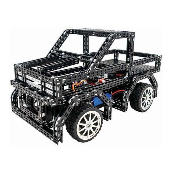
- Page 43 While the car can be driven immediately, you can create your own top chasis or use Totem prebuilt ones as inspiration. Once the battery runs out, it can be recharged with supplied Download Totemmaker charger. Connect it to the Charger IN port (1), and slide mode switch to CHARGE mode (2).
- Page 44 Last page...
Need help?
Do you have a question about the T.R.U.C.K. and is the answer not in the manual?
Questions and answers