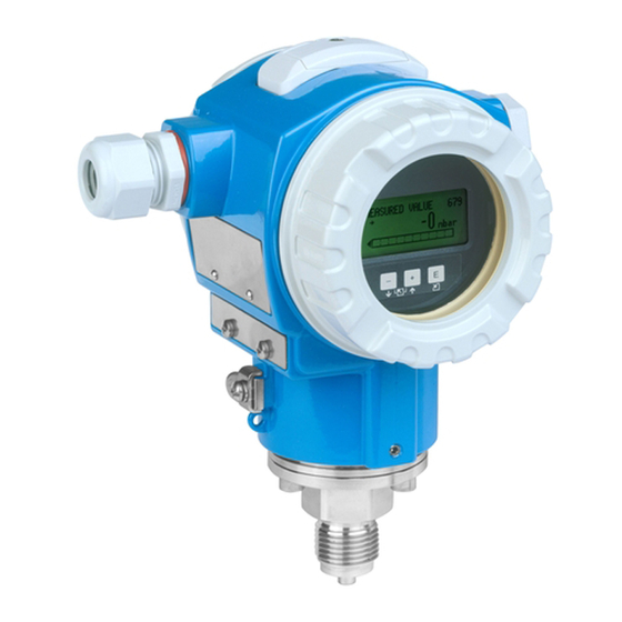
Endress+Hauser Cerabar S PMC71 Operating Instructions Manual
Process pressure measurement
Hide thumbs
Also See for Cerabar S PMC71:
- Operating instructions manual (238 pages) ,
- Technical information (136 pages) ,
- Manual (96 pages)

Related Manuals for Endress+Hauser Cerabar S PMC71


Summary of Contents for Endress+Hauser Cerabar S PMC71
-
Page 1: Operating Instructions
Products Solutions Services BA00295P/00/EN/18.16 71335661 valid from Software version 04.01.zz Operating Instructions Cerabar S PMC71, PMP71, PMP75 Process pressure measurement... - Page 2 The manufacturer reserves the right to modify technical data without prior notice. Your Endress+Hauser Sales Center will supply you with current information and updates to these Instructions. Endress+Hauser...
-
Page 3: Table Of Contents
Onsite operation – onsite display connected . . . 53 Endress+Hauser operating program ..56 HistoROM®/M-DAT (optional) ....56 Locking/unlocking operation . -
Page 4: Document Information
Document information Cerabar S PMC71, PMP71, PMP75 with PROFIBUS PA Document information Document function These Operating Instructions contain all the information that is required in various phases of the life cycle of the device: from product identification, incoming acceptance and storage, to mounting, connection, operation and commissioning through to troubleshooting, maintenance and disposal. -
Page 5: Registered Trademarks
Cerabar S PMC71, PMP71, PMP75 with PROFIBUS PA Document information 1.2.4 Symbols for certain types of information Symbol Meaning Permitted Indicates procedures, processes or actions that are permitted. A0011182 Forbidden Indicates procedures, processes or actions that are forbidden. A0011184 Indicates additional information. -
Page 6: Terms And Abbreviations
Document information Cerabar S PMC71, PMP71, PMP75 with PROFIBUS PA Terms and abbreviations A0029505 Position Term/Abbreviation Explanation The OPL (over pressure limit = sensor overload limit) for the sensors depends on the lowest-rated element, with regard to pressure, of the selected components, i.e. -
Page 7: Turn Down Calculation
Cerabar S PMC71, PMP71, PMP75 with PROFIBUS PA Document information Turn down calculation 1 = 2 A0029545 Fig. 1: 1Calibrated/Adjusted measuring span 2Zero-based span 3Upper range limit Example • Sensor: 10 bar (150 psi) • Calibrated/Adjusted measuring span: 0...5 bar •... -
Page 8: Basic Safety Instructions
The manufacturer is not liable for damage caused by improper or non-designated use. Verification for borderline cases: For special fluids and fluids for cleaning, Endress+Hauser is glad to provide assistance in verifying the corrosion resistance of fluid-wetted materials, but does not accept any warranty or liability. -
Page 9: Hazardous Area
Cerabar S PMC71, PMP71, PMP75 with PROFIBUS PA Basic safety instructions Hazardous area To eliminate a danger for persons or for the facility when the device is used in the hazardous area (e.g. explosion protection, pressure vessel safety): •Based on the nameplate, check whether the ordered device is permitted for the intended use in the hazardous area. -
Page 10: Identification
Identification Cerabar S PMC71, PMP71, PMP75 with PROFIBUS PA Identification Product identification The following options are available for identification of the measuring device: •Nameplate specifications •Order code with breakdown of the device features on the delivery note •Enter serial numbers from nameplates in W@M Device Viewer (www.endress.com/deviceviewer): All information about the measuring device is... - Page 11 Cerabar S PMC71, PMP71, PMP75 with PROFIBUS PA Identification A0021222 Fig. 3: Additional nameplate 1Approval-specific information 2Document number for safety instructions or drawing number Devices suitable for oxygen applications or with PVDF process connection are fitted with an additional nameplate.
-
Page 12: Scope Of Delivery
The device complies with the applicable standards and regulations as listed in the EC declaration of conformity and thus complies with the statutory requirements of the EC Directives. Endress+Hauser confirms the successful testing of the device by affixing to it the CE mark. -
Page 13: Installation
Cerabar S PMC71, PMP71, PMP75 with PROFIBUS PA Installation Installation Incoming acceptance, transport, storage 4.1.1 Incoming acceptance •Check the packaging and the contents for damage. •Check the shipment, make sure nothing is missing and that the scope of supply matches your order. -
Page 14: General Installation Instructions
•To ensure optimal readability of the onsite display, it is possible to rotate the housing up to 380°. See also ä 24, "Rotating the housing". •Endress+Hauser offers a mounting bracket for installing on pipes or walls. See also ä 21, "Wall and pipe mounting (optional)". - Page 15 Cerabar S PMC71, PMP71, PMP75 with PROFIBUS PA Installation ‣ If this is the case, mount the Cerabar S with the pressure compensation (1) pointing downwards. ® •Keep the pressure compensation and GORE-TEX filter (1) free from contamination and water.
- Page 16 Installation Cerabar S PMC71, PMP71, PMP75 with PROFIBUS PA Pressure measurement in steams ➀ ➃ ➁ ➁ ➂ ➀ P01-PMx7xxxx-11-xx-xx-xx-002 Fig. 7: Measuring arrangement for pressure measurement in steams 1Cerabar S 2Shutoff device 3U-shaped siphon 4Circular siphon •Use siphons for pressure measurement in steam. The siphon reduces the temperature to almost ambient temperature.
- Page 17 Cerabar S PMC71, PMP71, PMP75 with PROFIBUS PA Installation Level measurement P01-PMP75xxx-11-xx-xx-xx-000 Fig. 9: Measuring arrangement for level •Mount Cerabar S below the lowest measuring point. •Do not mount the device at the following positions: In the fill flow, in the tank outlet or at a point in the container which could be affected by pressure pulses from an agitator.
- Page 18 Installation Cerabar S PMC71, PMP71, PMP75 with PROFIBUS PA Vacuum application For applications under vacuum, Endress+Hauser recommends mounting the pressure transmitter below the diaphragm seal. This prevents vacuum loading of the diaphragm seal caused by the presence of fill fluid in the capillary.
- Page 19 Installation Mounting with temperature isolator Endress+Hauser recommends the use of temperature isolators in the event of constant extreme medium temperatures which lead to the maximum permissible electronics temperature of +85 °C (+185°F) being exceeded. Depending on the filling oil used, diaphragm seal systems with temperature isolators can be used for maximum temperatures of up to +400 °C (+752 °F).
- Page 20 Installation Cerabar S PMC71, PMP71, PMP75 with PROFIBUS PA 4.4.3 Seal for flange mounting NOTICE Corrupted measurement results. The seal is not allowed to press against the process isolating diaphragm as this could affect the measurement result. ‣ Ensure that the seal is not touching the process isolating diaphragm.
- Page 21 Cerabar S PMC71, PMP71, PMP75 with PROFIBUS PA Installation 4.4.5 Wall and pipe mounting (optional) Endress+Hauser offers a mounting bracket for installation on pipes or walls (for pipe diameters from 1 ¼" to 2"). ø42...60 (1.65...2.36) 122 (4.8) 140 (5.51) 158 (6.22)
- Page 22 Installation Cerabar S PMC71, PMP71, PMP75 with PROFIBUS PA 4.4.6 Assembling and mounting the "separate housing" version r ³ 120 (4.72) mm (in) P01-PMx7xxxx-11-xx-xx-xx-011 Fig. 15: "Separate housing" version 1In the "separate housing" version, the sensor is supplied with process connection and cable fitted.
- Page 23 See the "Welding recommendation" table below Engineering unit mm (in) Endress+Hauser recommends welding on the diaphragm seal as follows for the "XSJ - Prepared for diaphragm seal mount" version in feature 110 "Process connections" in the order code up to, and including, 40 bar (600 psi) sensors: the total welding depth of the fillet weld is 1 mm (0.04 in) with an outer diameter of 16 mm (0.63 in).
- Page 24 Installation Cerabar S PMC71, PMP71, PMP75 with PROFIBUS PA 4.4.8 Rotating the housing The housing can be rotated up to 380° by loosening the Allen screw. A0019996 1.T14 housing: Loosen setscrew with a 2 mm (0.08 in) Allen key. T15 andT17 housing: Loosen setscrew with a 3 mm (0.12 in) Allen key.
-
Page 25: Post-Installation Check
Cerabar S PMC71, PMP71, PMP75 with PROFIBUS PA Installation Post-installation check After installing the device, carry out the following checks: •Are all screws firmly tightened? •Are the housing covers screwed down tight? Endress+Hauser... -
Page 26: Wiring
Wiring Cerabar S PMC71, PMP71, PMP75 with PROFIBUS PA Wiring Connecting the device WARNING Risk of electric shock! If the operating voltage is > 35 VDC: Dangerous contact voltage at terminals. ‣ In a wet environment, do not open the cover if voltage is present. -
Page 27: Connecting The Measuring Unit
Cerabar S PMC71, PMP71, PMP75 with PROFIBUS PA Wiring 5.1.1 Connecting devices with an M12 connector PIN assignment for M12 connector Meaning Signal + Not assigned Signal – Earth A0011175 5.1.2 Connecting devices with 7/8" plug PIN assignment for 7/8" connector... -
Page 28: Overvoltage Protection (Optional)
Wiring Cerabar S PMC71, PMP71, PMP75 with PROFIBUS PA 5.2.2 Current consumption Up to HW Version 1.10: 11 mA ±1 mA, switch-on current corresponds to IEC 61158-2, Clause 21. As of HW Version 02.00: 13 mA ±1 mA, switch-on current corresponds to IEC 61158-2, Clause 21. -
Page 29: Operation
Cerabar S PMC71, PMP71, PMP75 with PROFIBUS PA Operation Operation Feature 20 "Output; operation" in the order code provides you with information on the operating options available to you. Versions in the order code Operation PROFIBUS PA; external and LCD... -
Page 30: Operating Elements
Operation Cerabar S PMC71, PMP71, PMP75 with PROFIBUS PA The following table illustrates the symbols that can appear on the onsite display. Four symbols can occur at one time. Symbol Meaning Alarm symbol – Symbol flashing: warning, device continues measuring. - Page 31 Cerabar S PMC71, PMP71, PMP75 with PROFIBUS PA Operation 6.2.2 Function of operating elements Operating elements Meaning – Position adjustment (zero point correction): Press key for at least 3 seconds. If the LED on the electronic insert lights up briefly, the pressure applied has been accepted for position adjustment.
- Page 32 Operation Cerabar S PMC71, PMP71, PMP75 with PROFIBUS PA 6.2.3 Function of the operating elements – onsite display connected Operating key(s) Meaning – Navigate upwards in the picklist – Edit the numerical values and characters within a function – Navigate downwards in the picklist –...
-
Page 33: Profibus Pa Communication Protocol
IEC 61158, IEC 61784, EN 50170/DIN 19245 and EN 50020 (FISCO model). 6.3.2 Number of devices •Endress+Hauser Cerabar S devices meet the requirements of the FISCO model. •Due to the low current consumption, the following can be operated at one bus segment when installation is performed according to FISCO: Up to HW Version 1.10:... - Page 34 Special configuration and operating programs from various manufacturers are available for configuring the device, such as the Endress+Hauser operating program FieldCare (see ä 56, "Endress+Hauser operating program"). This operating program makes it possible to configure PROFIBUS PA and the device-specific parameters. The predefined function blocks allow uniform access to all the network and device data.
- Page 35 Cerabar S PMC71, PMP71, PMP75 with PROFIBUS PA Operation Table of the identification numbers: Value for "IDENT Identification Selection text Status Diagnosis NUMBER SEL." number 0x9700 0x9700 Classic status / New diagnostic messages (Profile-specific 3.x) Condensed status 0x1501 0x1501 Classic status...
- Page 36 Operation Cerabar S PMC71, PMP71, PMP75 with PROFIBUS PA 6.3.5 Device identification and addressing Note the following points: •An address must be assigned to every PROFIBUS PA device. Only when the address is configured correctly will the device be recognized by the control system/master.
- Page 37 Cerabar S PMC71, PMP71, PMP75 with PROFIBUS PA Operation Configuring the new address using the FieldCare. DIP switch 8 (SW/HW) is set to "On" (SW): 1.Using the "Device Operation" menu select the "Connect" option. The "Open Connection Wizard" screen is displayed.
- Page 38 2) Each device receives an ID number from the Profibus User Organization (PNO). The name of the Device Master File (GSD) is derived from this. For Endress+Hauser, this ID No. starts with the manufacturer ID "15xx". 3) The Profile 3.02 GSD file with the "Condensed Status" option is only compatible with SW 04.01.zz and must be imported individually into the configura- tion tool.
- Page 39 Cerabar S PMC71, PMP71, PMP75 with PROFIBUS PA Operation The Device Master Files (GSD) for Endress+Hauser devices can be acquired in the following manner: •Internet Endress+Hauser: http://www.de.endress.com Download Search for "GSD" •Internet PNO: http://www.profibus.com (Products – Product Guide) •On CD-ROM from Endress+Hauser, order number: 56003894 The Profile Device Master Files (GSD) of the PNO can be acquired in the following manner: •Internet PNO: http://www.profibus.com (Products –...
- Page 40 Operation Cerabar S PMC71, PMP71, PMP75 with PROFIBUS PA 6.3.7 Cyclic data exchange Cerabar S block model Measured variable Sensor Display Physical Block Signal evaluation with scaling Device-specific characteristics, e.g. software revision SEL. DISPLAY VAL. PA Input value Main Process...
- Page 41 Cerabar S PMC71, PMP71, PMP75 with PROFIBUS PA Operation Description of parameters Parameter name Description OUT VALUE This parameter shows the digital output value of the Analog Input Block. Menu path FieldCare: PROFILE VIEW ANALOG INPUT BLOCK AI PARAMETER Menu path onsite display: GROUP SELECTION OPERATING MENU TRANSMITTER INFO PA DATA...
- Page 42 Operation Cerabar S PMC71, PMP71, PMP75 with PROFIBUS PA Modules for the cyclic data diagram Cerabar S makes the following modules available for the cyclic data diagram: •Main process value Depending on the operating mode selected, a pressure or level value is transmitted here.
- Page 43 Cerabar S PMC71, PMP71, PMP75 with PROFIBUS PA Operation Status codes Cerabar S supports the "Condensed status" function as defined in the PNO specification. However, the "Classic" status is also supported to ensure compatibility with older devices in the S series and due to the profile-specific identification number ("0x9700").
- Page 44 Operation Cerabar S PMC71, PMP71, PMP75 with PROFIBUS PA Status Device status Meaning Output value (OUT Value) 2ND CYCLIC code (Analog Input) VALUE 1000 GOOD Alarm limit - limit value undershot 1110 1) Only if the analog input failure behavior = 2 ("Status Bad") Condensed status: The main reason for implementing the "Condensed"...
- Page 45 Cerabar S PMC71, PMP71, PMP75 with PROFIBUS PA Operation 6.3.8 Acyclic data exchange Acyclic data exchange is used: •To transmit commissioning or maintenance parameters •To display measured variables not contained in the cyclic data diagram. Using acyclic data exchange, device parameters can be modified even when the device is involved in cyclic data exchange with a PLC.
- Page 46 Operation Cerabar S PMC71, PMP71, PMP75 with PROFIBUS PA 6.3.9 Slot/index tables The device parameters are listed in the following tables. You can access the parameters by means of the slot and index number. The individual blocks each contain standard parameters, block parameters and manufacturer-specific parameters.
- Page 47 Cerabar S PMC71, PMP71, PMP75 with PROFIBUS PA Operation Physical Block Parameter Slot Index Object type Data type Size (byte) Storage Class Read Write Physical Block standard parameters BLOCK OBJECT Record DS-32 STATIC REVISION NO. Simple Unsigned16 TAG_DESC Simple Visible String...
- Page 48 Operation Cerabar S PMC71, PMP71, PMP75 with PROFIBUS PA Parameter Slot Index Object type Data type Size (byte) Storage Class Read Write PCB TEMPERATURE Simple Float Allowed Min. TEMP Simple Float Allowed Max. TEMP Simple Float PCB COUNT: T>Tmax Simple Unsigned16 PCB MAX.
- Page 49 Cerabar S PMC71, PMP71, PMP75 with PROFIBUS PA Operation Transducer Block Parameter Slot Index Object type Data type Size (byte) Storage Class Read Write Transducer Block standard parameters BLOCK OBJECT Record DS-32 STATIC REVISION NO. Simple Unsigned16 TAG_DESC Simple Visible String...
- Page 50 Operation Cerabar S PMC71, PMP71, PMP75 with PROFIBUS PA Parameter Slot Index Object type Data type Size (byte) Storage Class Read Write COUNTER T<Tmin Simple Unsigned16 MEAS. VAL. TREND Simple Unsigned8 TOTALIZER 1 Simple Visible String TOTAL. 1 OVERFLOW Simple...
- Page 51 Cerabar S PMC71, PMP71, PMP75 with PROFIBUS PA Operation Parameter Slot Index Object type Data type Size (byte) Storage Class Read Write PERCENT UNIT Simple Unsigned16 X-VAL: Simple Float Y-VAL: Simple Float MASS FLOW UNIT Simple Unsigned16 SIM. FLOW VALUE...
-
Page 52: Data Format
Operation Cerabar S PMC71, PMP71, PMP75 with PROFIBUS PA 6.3.10 Data format In the case of PROFIBUS PA, the cyclic transmission of analog values to the PLC is effected in data blocks 5 bytes long. The measured value is portrayed in the first 4 bytes in the form of floating point numbers in accordance with IEEE standard. -
Page 53: Onsite Operation - Onsite Display Connected
Cerabar S PMC71, PMP71, PMP75 with PROFIBUS PA Operation Onsite operation – onsite display connected If the onsite display is connected, the three operating keys are used to navigate through the operating menu, see ä 32, "Function of the operating elements – onsite display connected". - Page 54 Operation Cerabar S PMC71, PMP71, PMP75 with PROFIBUS PA 6.4.2 Selecting an option Example: select "English" as the language of the menu. Onsite display Operation German is selected as the language. A 3 in front of the menu text indicates the active option.
- Page 55 Cerabar S PMC71, PMP71, PMP75 with PROFIBUS PA Operation 6.4.4 Editing a value Example: adjusting DAMPING VALUE function from 2.0 s to 30.0 s. See also ä 32, "Function of the operating elements – onsite display connected". Onsite display Operation The onsite display shows the parameter to be changed.
-
Page 56: Endress+Hauser Operating Program
Endress+Hauser operating program The FieldCare operating program is an Endress+Hauser asset management tool based on FDT technology. With FieldCare, you can configure all Endress+Hauser devices as well as devices from other manufacturers that support the FDT standard. Hardware and software requirements you can find on the internet: www.endress.com ... - Page 57 Cerabar S PMC71, PMP71, PMP75 with PROFIBUS PA Operation 6.6.1 Copying configuration data ➁ ➀ Zero Display Sensor S D A 0 1 2 3 4 5 6 7 8 Address HW-Version: SW-Version: P01-xxxxxxxx-19-xx-xx-xx-110 ® Electronic insert with optional HistoROM /M-DAT memory module ®...
- Page 58 Operation Cerabar S PMC71, PMP71, PMP75 with PROFIBUS PA The operation must be unlocked. 1.Disconnect device from supply voltage. ® 2.Attach the HistoROM /M-DAT module to the electronic insert. Configuration data from ® another device are stored in the HistoROM /M-DAT.
-
Page 59: Locking/Unlocking Operation
Cerabar S PMC71, PMP71, PMP75 with PROFIBUS PA Operation Locking/unlocking operation Once you have entered all the parameters, you can lock your entries against unauthorized and undesired access. You have the following possibilities for locking/unlocking the operation: •Via a DIP-switch on the electronic insert, locally on the display. -
Page 60: Factory Setting (Reset)
Operation Cerabar S PMC71, PMP71, PMP75 with PROFIBUS PA 6.7.2 Locking/unlocking operation via remote operation Description Locking operation 1. Select INSERT PIN No parameter, menu path onsite display: GROUP SELECTION OPERATING MENU OPERATING INSERT PIN No. menu path FieldCare: MANUFACTOR VIEW ... - Page 61 Cerabar S PMC71, PMP71, PMP75 with PROFIBUS PA Operation Reset code Description and effect 33333 User reset – This reset resets the following parameters: – POSITION ADJUSTMENT function group – BASIC SETUP function group, apart from customer-specific units – EXTENDED SETUP function group –...
-
Page 62: Commissioning
Commissioning Cerabar S PMC71, PMP71, PMP75 with PROFIBUS PA Commissioning The device is configured for the Pressure measuring mode at the factory. The measuring range and the unit in which the measured value is transmitted, as well as the digital output value of the Analog Input Block OUT, correspond to the data on the nameplate. -
Page 63: Commissioning Via Class 2 Master (Fieldcare)
Cerabar S PMC71, PMP71, PMP75 with PROFIBUS PA Commissioning Commissioning via Class 2 master (FieldCare) Commissioning and operating of FieldCare are described in the integrated FieldCare online help. Proceed as follows to commission the device: 1.Check the hardware write protection on the electronic insert (see ä 59, "Locking/ unlocking operation"). - Page 64 Commissioning Cerabar S PMC71, PMP71, PMP75 with PROFIBUS PA 7.4.2 FieldCare The MEASURING MODE parameter is displayed in the QUICK SETUP menus and in the BASIC SETUP function group (OPERATING MENU SETTINGS BASIC SETUP). The following measuring modes are available: •Pressure...
-
Page 65: Position Adjustment
Cerabar S PMC71, PMP71, PMP75 with PROFIBUS PA Commissioning Position adjustment Due to the orientation of the device, there may be a shift in the measured value, i.e. when the container is empty or partly filled, the measured value parameter does not display zero. -
Page 66: Pressure Measurement
Commissioning Cerabar S PMC71, PMP71, PMP75 with PROFIBUS PA Pressure measurement 7.6.1 Information on pressure measurement •The Level and Pressure operating modes each have a quick setup menu which guides you through the most important basic functions. With the setting in the MEASURING MODE parameter, you specify which Quick Setup menu should be displayed. - Page 67 Cerabar S PMC71, PMP71, PMP75 with PROFIBUS PA Commissioning Local operation FieldCare POS. INPUT VALUE POS. INPUT VALUE Due to orientation of the device, there may be a shift Due to orientation of the device, there may be a shift in the measured value.
-
Page 68: Level Measurement
Commissioning Cerabar S PMC71, PMP71, PMP75 with PROFIBUS PA Level measurement 7.7.1 Information on level measurement •The Level and Pressure operating modes each have a quick setup menu which guides you through the most important basic functions. See ä 70 for the "Level" quick setup menu. - Page 69 Cerabar S PMC71, PMP71, PMP75 with PROFIBUS PA Commissioning 7.7.2 Overview of level measurement Measuring task LEVEL SELECTION/ Measured Description Comment Measured value LEVEL MODE variable options display The measured variable is in LEVEL SELECTION: Via OUTPUT – Calibration with –...
- Page 70 Commissioning Cerabar S PMC71, PMP71, PMP75 with PROFIBUS PA 7.7.3 Quick Setup menu for the Level measuring mode •Some parameters are only displayed if other parameters are appropriately configured. For example, the EMPTY CALIB. parameter is only displayed in the following cases: –LEVEL SELECTION "Level Easy Pressure"...
- Page 71 Cerabar S PMC71, PMP71, PMP75 with PROFIBUS PA Commissioning Local operation FieldCare GROUP SELECTION Select QUICK SETUP menu. POS. ZERO ADJUST POS. ZERO ADJUST Due to orientation of the device, there may be a shift Due to orientation of the device, there may be a shift in the measured value.
-
Page 72: Scaling The Out Value
Commissioning Cerabar S PMC71, PMP71, PMP75 with PROFIBUS PA Scaling the OUT value In the Analog Input Block, the input value or input range can be scaled in accordance with the automation requirements. Example: The measuring range 0 to 500 mbar (0 to 7.5 psi) should be rescaled to 0 to 10000. -
Page 73: System Units (Set Unit To Bus)
Cerabar S PMC71, PMP71, PMP75 with PROFIBUS PA Commissioning System units (SET UNIT TO BUS) The onsite display of Cerabar S and the MEASURED VALUE (FieldCare) display the same value as standard. The bar graph on the onsite display corresponds to the standardized value of the Analog Input Block. -
Page 74: Maintenance
(1) free from contamination and water. P01-PMC71xxx-17-xx-xx-xx-001 Cleaning instructions Endress+Hauser offer flushing rings as accessories to clean process isolating diaphragms without taking the transmitters out of the process. For further information please contact your local Endress+Hauser Sales Center. 8.1.1... -
Page 75: Troubleshooting
Cerabar S PMC71, PMP71, PMP75 with PROFIBUS PA Troubleshooting Troubleshooting Messages The following table lists all the possible messages that can occur. The device differentiates between the error types "Alarm", "Warning" and "Error". You may specify whether the instrument should react as if for an "Alarm" or "Warning" for "Error"... - Page 76 Troubleshooting Cerabar S PMC71, PMP71, PMP75 with PROFIBUS PA Code Correspond Message Message/description Cause Measure Priorit s to NA 64 category NE 107 110 (A110) Alarm Failure (F) F>Checksum error in – The supply voltage is – Reestablish supply voltage.
- Page 77 Cerabar S PMC71, PMP71, PMP75 with PROFIBUS PA Troubleshooting Code Correspond Message Message/description Cause Measure Priorit s to NA 64 category NE 107 Warning Function C>Linearization table Note! No min. span applies for the Y-points as of software version (W604) check (C) not valid.
- Page 78 Troubleshooting Cerabar S PMC71, PMP71, PMP75 with PROFIBUS PA Code Correspond Message Message/description Cause Measure Priorit s to NA 64 category NE 107 Warning Maintenanc M>Configuration in – Configuration (parameters) in – Copy data from the device to the (W706)
- Page 79 Cerabar S PMC71, PMP71, PMP75 with PROFIBUS PA Troubleshooting Code Correspond Message Message/description Cause Measure Priorit s to NA 64 category NE 107 717 (E717) Error Out of S>Transmitter over – The temperature measured in – Reduce ambient temperature. specificatio...
- Page 80 Troubleshooting Cerabar S PMC71, PMP71, PMP75 with PROFIBUS PA Code Correspond Message Message/description Cause Measure Priorit s to NA 64 category NE 107 727 (E727) Error Out of S>Sensor pressure error – Electromagnetic effects are – Block off electromagnetic effects...
- Page 81 Cerabar S PMC71, PMP71, PMP75 with PROFIBUS PA Troubleshooting Code Correspond Message Message/description Cause Measure Priorit s to NA 64 category NE 107 736 (A736) Alarm Failure (F) F>RAM error – Fault in the main electronics. – Briefly disconnect device from the power supply.
- Page 82 Troubleshooting Cerabar S PMC71, PMP71, PMP75 with PROFIBUS PA Code Correspond Message Message/description Cause Measure Priorit s to NA 64 category NE 107 Warning Function C>Sensor connection – Electromagnetic effects are – Wait a few minutes. (W746) check (C) error - initializing greater than specifications in –...
-
Page 83: Response Of Outputs To Errors
Cerabar S PMC71, PMP71, PMP75 with PROFIBUS PA Troubleshooting Response of outputs to errors The device differentiates between the message types "Alarm", "Warning" and "Error". See the following table and Page 75, Section 8.1 "Messages". Output A (Alarm) W (Warning) - Page 84 Troubleshooting Cerabar S PMC71, PMP71, PMP75 with PROFIBUS PA 9.2.1 Analog Input Block If the Analog Input Block receives an input or simulation value with the status Bad, the Analog Input Block uses the failsafe mode defined in the FAIL SAFE MODE parameter.
-
Page 85: Confirming Messages
Cerabar S PMC71, PMP71, PMP75 with PROFIBUS PA Troubleshooting 1.In the FieldCare navigation window navigate to PROFILE VIEW PB Parameter 2.In the default setting, all the bits have "Uncertain" for "Status Select Events", apart from 716. 3.Select the "Bad" option for the row "Status Select Event 115". Press the Enter key to confirm. -
Page 86: Repair
•Carry out repairs according to the instructions. After repairs, the device must fulfil the requirements of the specified individual tests. •A certified device may only be converted into another certified variant by Endress+Hauser. •All repairs and modifications must be documented. -
Page 87: Software History
Cerabar S PMC71, PMP71, PMP75 with PROFIBUS PA Troubleshooting Software history Date Software version Changes software Documentation Operating Instructions Description of Instrument Functions 12.2004 03.00.zz Original software. BA295P/00/EN/11.04 — 52025890 Compatible with: ® – Update ToF Tool – Field Tool Package, version 2.03... -
Page 88: Technical Data
Technical data Cerabar S PMC71, PMP71, PMP75 with PROFIBUS PA Technical data For technical data, please refer to the Technical Information TI00383P for Cerabar S. Endress+Hauser... -
Page 89: Index
Cerabar S PMC71, PMP71, PMP75 with PROFIBUS PA Index Acyclic data exchange ......45 Nameplate . - Page 90 Cerabar S PMC71, PMP71, PMP75 with PROFIBUS PA Wall mounting ........21 Warnings .
- Page 91 Cerabar S PMC71, PMP71, PMP75 with PROFIBUS PA Endress+Hauser...
- Page 92 71335661 www.addresses.endress.com...
Need help?
Do you have a question about the Cerabar S PMC71 and is the answer not in the manual?
Questions and answers