Table of Contents
Advertisement
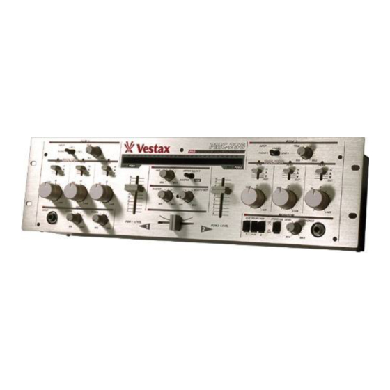
Professional Mixing Controller
OWNER'S MANUAL
VESTAX CORPORATION
1-18-6 Wakabayashi, Setagaya-ku, Tokyo 154-0023 Japan
Phone:03-3412-7011 Fax: 03-3412-7013
Web:www.vestax.jp
VESTAX America (west Corst)
15320 Valley View Rord Unit 9 La Mirada, CA 90638
Phone:(562)623-9881 Fax:(562)483-7304
Web:www.vestaxdj.com
VESTAX ( Europe ) Ltd.
Unit 5 Riverwey Industrial Park Alton, Hampshire GU34 2QL England, U.K
Phone:(0)1420-83000 Fax: (0)1420-80040
Web:www.vestax.co.uk
Vestax Technical Center of America
8489 W.Third Street Ste.1044 Los Angeles CA 90048
Phone:1-323-801-2111 Fax:1-323-801-2112
Vestax Europe Technical Support
Rheinstr.213 D-53332 Bornheim Germany
Phone:49(0)2222-95-23-72 Fax:49(0)2222-95-23-74
Advertisement
Table of Contents

Summary of Contents for Vestax PMC 250
- Page 1 VESTAX America (west Corst) 15320 Valley View Rord Unit 9 La Mirada, CA 90638 Phone:(562)623-9881 Fax:(562)483-7304 Web:www.vestaxdj.com VESTAX ( Europe ) Ltd. Unit 5 Riverwey Industrial Park Alton, Hampshire GU34 2QL England, U.K Phone:(0)1420-83000 Fax: (0)1420-80040 Web:www.vestax.co.uk Vestax Technical Center of America 8489 W.Third Street Ste.1044 Los Angeles CA 90048...
-
Page 2: Table Of Contents
CONGRATULATIONS ! Thank you for purchasing the VESTAX PMC-250, Professional Mixing Controller. Please read this owner's manual carefully before you start to use your mixer, so that you will fully understand all of the special features and enjoy the full use of the product. -
Page 3: Important Safeguards
I M P O R T A N T S A F E G U A R D S READ BEFORE OPERATING EQUIPMENT This product was designed and manufactured to meet strict quality and safety standards. There are, however, some installation and operation precautions which you should be particularly aware of. -
Page 4: F E A T U R E S
15. Damage Requiring Service-Unplug this product from the wall outlet and refer servicing to qualified service personnel under the following conditions: a. When the power-supply cord or plug is damaged. b. If liquid has been spilled or objects have fallen into the product. -
Page 5: F U N C T I O N S
F U N C T I O N S PROGRAM SECTION PGM 1 INPUT TRIM LINE 1 PHONO 1 LINE 2 ISOLATOR ISOLATOR PEAK PEAK PEAK ∞ + 4dB ∞ + 4dB ∞ + 4dB INPUT LEVEL FILTER MIC SECTION PROGRAM SECTION q INPUT SELECT (Input Select Switch) Used to select input to be sent to each PGM... -
Page 6: Master Section
u HI CUT (Fader type cut switch HI) When this volume is set to bottom position, high frequency range is cut of completely regardless of the position of the HI level control. The HI level control knob becomes active when this volume is set to maximum (top)... -
Page 7: Monitor Section
MONITOR SECTION MONITOR CUE SELECTOR STEREO CUE LEVEL @1 CUE SELECTOR Used to select the cue signal to be monitored by headphones from PGM1, PGM2 or AUX. REAR PANEL SECTION @5 PHONO 1,2 [RCA PIN JACK] Connect turntables equipped with MM (Moving Magnet type) cartridge. -
Page 8: Connection (Example
C O N N E C T I O N E X A M P L E Instruments connected to the PGM 2 Instruments connected to th TURNTABLE[VESTAX PDX-2000] CDPLAYER[Vestax CDX-35] PHONO2 LINE3 LINE4 UNBALANCED INPUT MONITOR SYSTEM POWER AMPLIFIER [Vestax PT-X1000A]... -
Page 9: How To Change The Fader Unit
HOW TO CHANGE THE FADER UNIT ■HOW TO REMOVE THE TOP PANEL ○ Remove all slide fader knobs' and screws on the top panel. ○ Remove the top panel. ■HOW TO CHANGE THE FADER UNIT ○ Remove the screws on the fader panel. ○... -
Page 10: How To Change The Jack Panel Position
HOW TO CHANGE THE JACK PANEL POSITION The I/O jack panel of the PMC-250 can be placed either on the top or back side of the unit. Please refer to following Fig. Initially, the I/O panel is placed on the top-side. In case of changing the jack panel position to TYPE □... -
Page 11: Block Diagram
BLOCK DIAGRAM... -
Page 12: Specifications
30Hz ∼ 20kHz ±3dB FREQUENCY RESPONSE LINE 20Hz ∼ 20kHz ±1dB >60dB S/N RATIO LINE >75dB FADER >70d B ATTENUATION Vestax Corporation NOMINAL INPUT MAXIMUM INPUT LEVEL -50dBv -42dBv -10/0/+6dBv -10dBv -10dBv CROSSFADER CROSSTALK CHANNEL CROSSTALK POWER SUPPLY DIMENSIONS (W×H×D)...


Need help?
Do you have a question about the PMC 250 and is the answer not in the manual?
Questions and answers