Table of Contents
Advertisement
Quick Links
Download this manual
See also:
Owner's Manual
Advertisement
Table of Contents

Subscribe to Our Youtube Channel
Related Manuals for Vestax PCV-002


Summary of Contents for Vestax PCV-002
- Page 1 VESTAX SERVICE NOTE MODEL: PCV-002 1. SPECIFICATIONS P. 2-P. 5 SCHEMATIC DIAGRAM P. 6-P. 10 PARTS LIST P. 11- P. 14 SPARE PARTS LIST P. 15- P. 16 Vestax Corporation Service Department (2003-07-22)
-
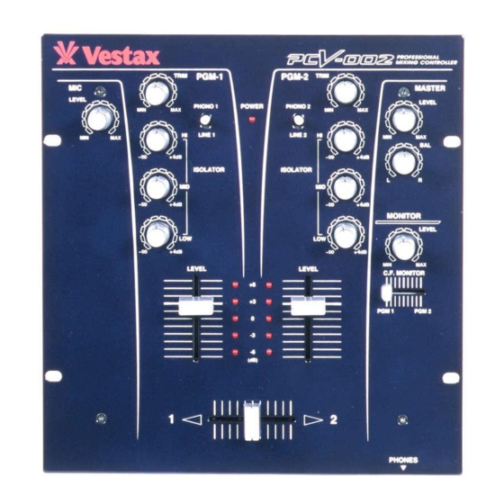
Page 3: Controls And Functions
CONTROLS AND FUNCTIONS 4 1 4 TOP PANEL q POWER LED i PHONES JACK The LED is lit when power is on. Use this jack to connect the head phones. Head phones from 8 ohm to 600 ohm can be used. w INPUT SELECT SWITCH 150 ohm is recommended. - Page 4 How to change the fader unit. HOW TO REMOVE THE TOP PANEL driver Remove all fader knobs and the 4screws which fix the top panel.(see fig.A) Remove the top panel. HOW TO CHANGE THE FADER UNIT Remove the screws on the fader panel.(see fig.B) Remove the fader unit from position in mixer.
-
Page 5: Rear Panel
SHOCK. DO NOT OPEN WARNING;SHOCK HAZARD-DO NOT OPEN. AVIS;RISQUE DE CHOC ELELCTRIQUE -NE PAS OUVRIR. OUTPUT PGM 2 PGM 1 MADE IN CHINA UNDER LICENCE OF VESTAX TOKYO, JAPAN LINE 2 LINE 1 SERIAL NO. DC IN LINE PHONO 2... -
Page 6: Specifications
SECTION MAXIMUM OUTPUT IMPEDANCE HEADPHONE 1/4" PHONE JACK 70mW 47 load FREQUENCY RESPONSE 20Hz 20KHz CROSS TALK 100dB S/N RATIO -82dB POWER SUPPLY DC15V 500mA DIMENSIONS W H D 248 105 261 mm WEIGHT 3.5kg Vestax Corporation MAY.2002 PCV002E q... - Page 8 47u/16 PHONE PGM2 Rch 10KA*2 MIC IN 10u/16 330K R132 HLJ0546-01-110 C128 C122 3.3k MIC JACK •i‹à‘®JACK+PLASTIC BUSH•j Title PCV-002U —ÊŽY•} ‰ü’ù•@2002.1.7 Size Number Revision (R88•AR93 •` 27K•¨15K) (C132 •`•@100u/16•¨100u/25) 2001.11.20 Date: 7-Jan-2002 Sheet of File: D:\Vestax\..\PCV002—ÊŽY•}.asc Drawn By: AIMI...
- Page 9 +Vcc +Vcc PHONE PGM1 Lch PHONE PGM2 Lch PHONE PGM1 Rch PHONE PGM2 Rch Title Output, Phones Size Number Revision Date: 7-Jan-2002 Sheet of File: D:\Vestax\..\PCV002—ÊŽ Y• }.asc Drawn By:...
-
Page 10: Input Power
+Vcc +Vcc 1/2VP1 1/2VP2 +Vcc Input +Power... - Page 11 1/2VP2 1/2VP2 +Vcc 1/2VP2 1/2VP2 PHONE PGM2 Lch 1/2VP2 1/2VP2 1/2VP2 +Vcc +Vcc 1/2VP2 1/2VP2 1/2VP2 1/2VP2 1/2VP2 +Vcc 1/2VP2 1/2VP2 1/2VP2 +Vcc 1/2VP2 1/2VP2 1/2VP2 1/2VP2 PHONE PGM2 Rch 1/2VP2 1/2VP2 1/2VP2 1/2VP2 1/2VP2 1/2VP2 +Vcc 1/2VP2 +Vcc +Vcc +Vcc Mic;...
-
Page 12: Led Control
+Vcc +Vcc LED Control...
Need help?
Do you have a question about the PCV-002 and is the answer not in the manual?
Questions and answers