Advertisement
Quick Links
Advertisement

Related Manuals for Vestax PCV-007


Summary of Contents for Vestax PCV-007
- Page 1 PCV-007 Email: tech@vestax.com...
- Page 2 VESTAX SERVICE NOTE MODEL: PMC-007 SPECIFICATIONS P. 3 - P. 8 CIRCUIT DIAGRAM P. 9 - P. 16 COMPONENTS LIST P. 17 - P. 46 PCB LAYOUT P. 47 - P. 53 Vestax Corporation Service Department (2005-04-01)
-
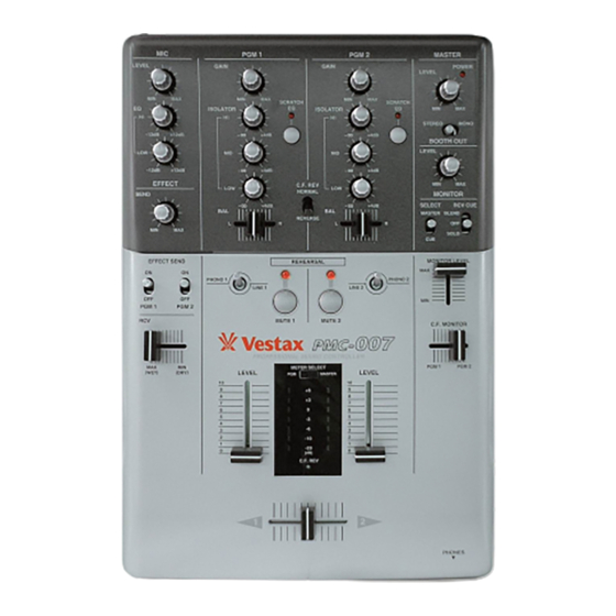
Page 3: Top Panel
F U N C T I O N S TOP PANEL 8 11... - Page 4 !4 BOOTH LEVEL q MIC LEVEL This knob is used to adjust the level of output through the This switch is used to adjust the signal level of the Main Booth section. MIC input. !5 MONITOR SELECT SWITCH w MIC EQ This switch is used to select which type of monitor signal, The2-Band MIC EQ feature is used to adjust the equalization either CUE or MASTER, is heard in headphones connected...
-
Page 5: Front Panel
PGM. The input fader on this unit is a PCV fader and utilizes that the input levels of both PGM 1 and PGM 2 are properly Vestax ReX fader exchange technology. This fader is user set, then when the CF is at position 1 the signals from PGM 1 replaceable. -
Page 6: Rear Panel
1/4 inch output can be used as a sub unbalanced output. channel is Effect Send and the R channel is Effect Receive. $2 POWER JACK TIP: ………………MIC SEND OUT Connect the Vestax AC-12A, AC adaptor (12V AC, RING: ……………MIC RECEIVE OUT 1000mA). SLEEVE:…………EARTH... -
Page 7: How To Change The Fader Unit
Vestax service center. i Lower the Battle Panel as illustrated taking care to realign the fader slots and fader forks properly. This panel will Note not close if realigned incorrectly. -
Page 8: Specification
PMC -007 SPECIFICATION NOMINAL INPUT MAXIMUM INPUT INPEDANCE MIC (φ6.3 PHONE JACK) -50.0dBv -32.0dBv 3.3kΩ PHONO 1.2L R (RCA PIN JACK) -46.0dBv -22.4dBv 56kΩ / INPUT LINE 1.2L R (RCA PIN JACK) 0dBv +14dBv 16kΩ / SECTION EFFECT RCV (RCA PIN JACK UNBALANCED) 0dBv +14dB 42kΩ MIC RCV (TRS PHONE JACK-RING PIN) 0dBv +14dB 69kΩ HI 10kHz - ∞ 〜...
Need help?
Do you have a question about the PCV-007 and is the answer not in the manual?
Questions and answers