Advertisement
Quick Links
Advertisement

Subscribe to Our Youtube Channel
Related Manuals for Ryobi RLT-800


Summary of Contents for Ryobi RLT-800
- Page 1 RLT-800 6986295 (STD) 06-11...
- Page 2 THANK YOU FOR BUYING A RYOBI ELECTRIC LINE TRIMMER Your new line trimmer has been engineered and manufactured to Ryobi’s high standard of dependability, ease of operation, and operator safety. Properly cared for, it will give you years of rugged, trouble free performance. If you use your line trimmer properly and only for what it is intended, you will enjoy years of safe, reliable service.
- Page 3 SAFETY ALERT SYMBOL Indicates danger, caution or warning. May be used in conjunction with other symbols or pictures.
- Page 5 SPECIFIC SAFETY rulES For lInE TrImmEr 1. Your line trimmer is a high-speed, fast cutting 17. Protect your extension cable from sharp objects, power tool. The electrical connection and cutting excessive heat, and damp or wet locations. tools are potential sources of danger. Therefore, 18.
- Page 6 SPECIFIC SAFETY rulES For lInE TrImmEr 32. Warning! 33. Always ensure that ventilation openings are kept clear of debris. 1) The nylon line continues to rotate after the motor is switched off. 34. Take care against injury from the blade fitted for trimming the cutting line.
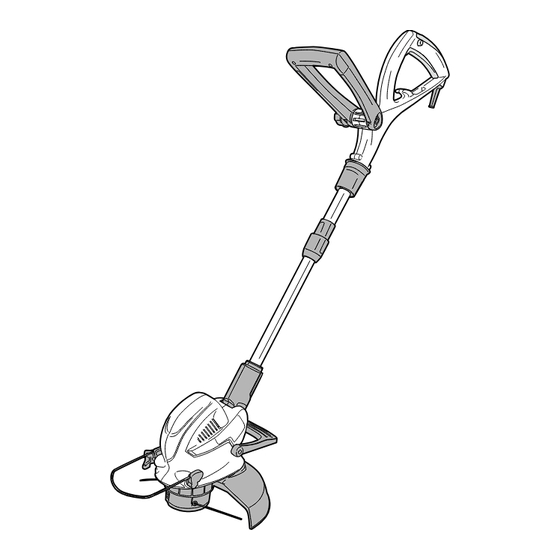
- Page 7 dESCrIPTIon 9. Telescopic tube 1. Rear handle 10. Motor housing 2. Cable strain relief arm 11. Edge guide 3. Safety button 12. Foot pedal for head angle adjustment 4. Trigger switch 13. Safety guard 5. Auxiliary handle 14. Cutting head 6.
- Page 8 ASSEmBlY Warning! do not connect the machine to the mains socket before it is completely assembled. FITTInG GuArd (Fig.1) Fig. 1 1. Put the safety guard (13) in place. 2. Secure the safety guard onto the motor housing (10) with screws provided. AdJuSTInG AuXIlIArY HAndlE (Fig.
-
Page 9: Operation
ASSEmBlY AdJuSTInG PIVoT HEAd (Fig. 4) Fig. 4 1. D e p r e s s t h e f o o t p e d a l f o r h e a d a n g l e adjustment (12), and move the trimmer head up or down to desired position and release the foot pedal. - Page 10 OPERATION TRIMMING 1. Use the trimmer at an angle of approximately (Fig.7) 15-degree to the working area 2. Slowly swing the trimmer from side to side. (Fig.8) 3. Do not overload your trimmer, take small “bites” this will keep machine operating at high speed and will greatly improve cutting efficiency, (Fig.9) Fig.
- Page 11 oPErATIon mAnuAllY FEEd lInE (Fig. 11) If required line can be fed out manually, press and release manual line feed button (15), whilst gently pull out the lines until the lines reach the line cutter. When the required amount of line is fed out, gently pull on the second line (there is no need to press the manual line feed button again) If the line extends past the line cutter, too much...
- Page 12 oPErATIon rEPlACInG CuTTInG lInE In SPool (Fig. 13) Use 2.0mm diameter round nylon line. 1. Remove the thread spool, and remove any old line remaining on the spool. 2. Bend a new thread in the middle, and hook into the spool. (Fig.13-A) 3.
-
Page 13: Troubleshooting
8. There are no user serviceable parts in the trimmer. If a fault is suspected return the trimmer to an authorized dealer for repair. ImPorTAnT : To assure product safety and reliability, repairs, maintenance and adjustment should be performed by RYOBI authorized service centers or other qualified service organization, always using identical replacement parts. TrouBlESHooTInG 1. - Page 14 noTES...
- Page 15 noTES...
- Page 16 RYOBI tool (hereinafter called “the Product”), for which it was not designed, or is not suited is warranted by Ryobi (herein called “the and no repairs, alterations or modifications Company”) to be free from defects in material...
Need help?
Do you have a question about the RLT-800 and is the answer not in the manual?
Questions and answers