Table of Contents
Advertisement
Quick Links
Technical Manual
Of
Intel Braswell Series CPU
Based
SBC
NO.G03-NP793-F
Revision: 4.0
Release date: February 17, 2020
Trademark:
* Specifications and Information contained in this documentation are furnished for information use only, and are
subject to change at any time without notice, and should not be construed as a commitment by manufacturer.
Advertisement
Table of Contents

Related Manuals for JETWAY JNP793D2-3160


Summary of Contents for JETWAY JNP793D2-3160
- Page 1 Technical Manual Intel Braswell Series CPU Based NO.G03-NP793-F Revision: 4.0 Release date: February 17, 2020 Trademark: * Specifications and Information contained in this documentation are furnished for information use only, and are subject to change at any time without notice, and should not be construed as a commitment by manufacturer.
- Page 2 Environmental Protection Announcement Do not dispose this electronic device into the trash while discarding. To minimize pollution and ensure environment protection of mother earth, please recycle.
-
Page 3: Table Of Contents
TABLE OF CONTENT ENVIRONMENTAL SAFETY INSTRUCTION ................iv USER’S NOTICE ........................v MANUAL REVISION INFORMATION ..................v ITEM CHECKLIST ........................v CHAPTER 1 INTRODUCTION OF THE MOTHERBOARD FEATURE OF MOTHERBOARD ................1 SPECIFICATION ......................2 LAYOUT DIAGRAM ....................3 MECHANICAL DRAWING ..................5 CHAPTER 2 HARDWARE INSTALLATION JUMPER SETTING .....................6 CONNECTORS, WAFERS AND HEADERS ..............9 CHAPTER 3 INTRODUCING BIOS ENTERING SETUP .....................15... -
Page 4: Environmental Safety Instruction
Environmental Safety Instruction Avoid the dusty, humidity and temperature extremes. Do not place the product in any area where it may become wet. 0 to 60 centigrade is the suitable temperature. (The figure comes from the request of the main chipset) ... -
Page 5: User's Notice
USER’S NOTICE COPYRIGHT OF THIS MANUAL BELONGS TO THE MANUFACTURER. NO PART OF THIS MANUAL, INCLUDING THE PRODUCTS AND SOFTWARE DESCRIBED IN IT MAY BE REPRODUCED, TRANSMITTED OR TRANSLATED INTO ANY LANGUAGE IN ANY FORM OR BY ANY MEANS WITHOUT WRITTEN PERMISSION OF THE MANUFACTURER. -
Page 6: Chapter 1 Introduction Of The Motherboard
Chapter 1 Introduction of the Motherboard 1-1 Feature of Motherboard Intel® Braswell SoC Processor, with low power consumption never denies high performance Support on-board 2GB DDR3L DRAM Equipped with 32GB on-board eMMC Onboard 1* full-size Mini-PCIE slot ... -
Page 7: Specification
1-2 Specification Spec Description PCB size: 2.5’’ (100 mm x 72 mm) Design Intel ® Braswell *SoC CPU Embedded CPU *CPU model varies from different IPC options. Please consult your dealer for more information of onboard CPU Onboard 2GB DDR3L DRAM ... -
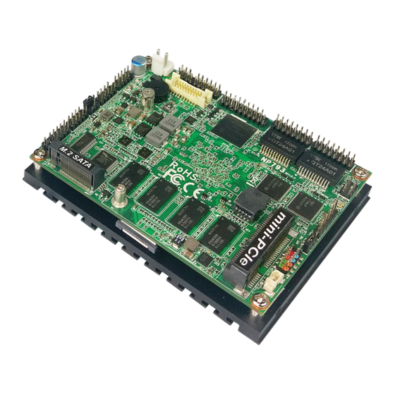
Page 8: Layout Diagram
1-3 Layout Diagram Internal Diagram-Front Side: COM2 COM1 GPIO USB 2.0 Port Header Header Header Header AT_MODE 12V DC-in JPCOM1 Power Connector M.2 SATA Slot (M.2) EDP Port HDMI Port Wafer Header USB 3.0 Port Header Onboard DRAM RJ-45 LAN Port Onboard Header eMMC... - Page 9 Jumper Jumper Name Description Pin (1-2): Clear CMOS RAM Settings 6-Pin Block Pin (3-4): RTC Reset Pin (5-6): Flash Descriptors Override MPE_PWR MPE Slot VCC 3V/3.3VSB Select 3-Pin Block AT_MODE AT/ATX Mode Select 3-Pin Block JPCOM1 COM1 Port Pin-9 Function Select 4-Pin Block Internal Connectors, Wafer &...
-
Page 10: Mechanical Drawing
1-4 Mechanical Drawing Unit=mm. -
Page 11: Jumper Setting
Chapter 2 Hardware Installation 2-1 Jumper Setting Pin 1&2 of JP1 (6-pin): Clear CMOS RAM Setting Pin (1&2) of JP1 → Clear CMOS Pin 1 1-2 Open: Normal(Default); Pin 1 1-2 Closed: Clear CMOS(One Touch). Pin 3&4 of JP1 (6-pin): RTC Reset Select Pin (3&4) of JP1 →... - Page 12 Pin 5&6 of JP1 (6-pin): Flash Deacriptors Override Select → Pin (5&6) of JP1 Flash Override Pin 1 5-6 Open:Enable Security Measures in the Flash Descriptor(Default); Pin 1 5-6 Closed: Disable Security Measures in the Flash Descriptor(Override). MPE_PWR (3-pin): MPE Slot VCC 3V/3VSB Select MPE_PWR →...
- Page 13 AT_MODE (3-pin): AT Mode /ATX Mode Select AT_MODE → ATX/AT Mode Select AT_MODE 1-2 Closed: ATX Mode Selected; 2-3 Closed: AT Mode Selected. *ATX Mode Selected: Press power button to power on after power input ready; AT Mode Selected: Directly power on as power input ready. JPCOM1 (4-pin): COM1 Port Pin9 Function Select JPCOM1 JPCOM1...
-
Page 14: Connectors, Wafers And Headers
2-2 Connectors, Wafers and Headers (1) DCIN1(2-pin) : Internal 12V DC-in power connector DCIN1 Pin1 Pin No. Definition +12V (2) JW_FP (9-pin): Front Panel Header Pin 1 JW_FP... - Page 15 (3) SMBUS (5-pin): SMBUS Header Pin 1 SMBUS (4) GPIO (10-pin): GPIO Header GPIO Pin 1...
- Page 16 (5) COM1/2 (9-pin): Serial Port Headers : COM1 RS232/422/485 Serial Port Header; : COM2 RS232 Serial Port Header. COM2 COM1 Pin 1 Pin NO. RS232 *RS422 *RS485 Pin 1 DATA- Pin 2 DATA+ Pin 3 Pin 4 Pin 5 Pin 6 Pin 7 Pin 8 Pin 9...
- Page 17 (6) FP_USB20 (9-pin): USB 2.0 Port Wafer FP_USB20 Pin 1 (7) USB30 (5-pin): USB 3.0 Port Header SSTX2+ SSTX2- SSTX1+ USB30 SSTX1- SSRX2+ SSRX2- SSRX1+ SSRX1- VBUS VBUS Pin 1...
- Page 18 (8) EDP1 (20-pin): EDP Wafer EDP1 Pin1 Pin Define Pin Define EDP_POWER EDP_POWER EDP_DATA1N EDP_DATA1P EDP_Backlight power EDP_DATA0N EDP_Backlight power EDP_DATA0P EDP_HPD EDP_AUXP Backlight enable EDP_AUXN Backlight PWM...
- Page 19 (9) HDMI (19-pin): HDMI Port Header HDMI_HPD HDMI_5V DDC_SDA DDC_SCL TMDS_CLKN DATA0N TMDS_CLKP DATA0P DATA1N HDMI DATA2N DATA1P DATA2P Pin 1 LAN1/LAN2 (15-pin): LAN Header (10) LAN2 MDI_0- MDI_0+ MDI_1- MegaLAN LED- MDI_1+ MDI_2- Link Act LED- LAN1 GigaLAN LED- MDI_2+ MDI_3- 3VSB...
-
Page 20: Chapter 3 Introducing Bios
Chapter 3 Introducing BIOS Notice! The BIOS options in this manual are for reference only. Different configurations may lead to difference in BIOS screen and BIOS screens in manuals are usually the first BIOS version when the board is released and may be different from your purchased motherboard. Users are welcome to download the latest BIOS version form our official website. -
Page 21: Bios Menu Screen
BIOS Menu Screen The following diagram show a general BIOS menu screen: Menu Bar General Help Items Current Setting Value Menu Items Function Keys BIOS Menu Screen... -
Page 22: Function Keys
Function Keys In the above BIOS Setup main menu of, you can see several options. We will explain these options step by step in the following pages of this chapter, but let us first see a short description of the function keys you may use here: ... -
Page 23: Memu Bars
3-5 Menu Bars There are six menu bars on top of BIOS screen: Main To change system basic configuration Advanced To change system advanced configuration Chipset To change chipset configuration Security Password settings Boot To change boot settings Save & Exit Save setting, loading and exit options. -
Page 24: Advanced Menu
System Date Set the date. Please use [Tab] to switch between date elements. System Time Set the time. Please use [Tab] to switch between time elements. 3-7 Advanced Menu Trusted Computing Press [Enter] to enable or disable ‘Security Device Support’. Configuration Security Device Support Use this item to enable or disable BIOS support for security device. - Page 25 ACPI Settings ACPI Sleep State Use this item to select the highest ACPI sleep state the system will enter when the suspend button is pressed. The optional settings are: [Suspend Disabled]; [S3 (Suspend to RAM)]. Super I/O Configuration Press [Enter] to make settings for the following sub-items: Super IO Configuration ...
- Page 26 Use this item to enable or disable serial port (COM). The optional settings are: [Enabled]; [Disabled]. When set as [Enabled], the following sub-items shall appear: Change Settings Use this item to select an optimal setting for super IO device. The optional settings are: [Auto]; [IO=3F8h; IRQ=4]; [IO=2F8h; IRQ=3]; [IO=3E8h; IRQ=4];...
- Page 27 User can select a value in the range of [10] to [4095] seconds when ‘WatchDog Wake-up Timer Unit’ set as [Sec]; or in the range of [1] to [4095] minutes when ‘WatchDog Wake-up Timer Unit’ set as [Min]. WatchDog Wake-up Timer Unit The optional settings are: [Sec.];...
- Page 28 The optional settings: [7]; [8]. Parity A parity bit can be sent with the data bits to detect some transmission errors. The optional settings: [None]; [Even]; [Odd]; [Mark]; [Space]. Even: parity bit is 0 if the num if 1’s in the data bits is even; Odd: parity bit is 0 if num of 1’s in the data bits is odd;...
- Page 29 Putty KeyPad Use this item to select FunctionKey and KeyPad on Putty. The optional settings: [VT100]; [Intel Linux]; [XTERMR6]; [SCO]; [ESCN]; [VT400]. Redirection After BIOS POST The optional settings are: [Always Enable]; [BootLoader]. Whet Bootloader is selected, then Lagacy Console Redirection is disabled before booting to legacy OS.
- Page 30 Use this item to select serial port transmission speed. The speed must be matched on the other side. Long or noisy lines may require lower speeds. The optional settings: [9600]; [19200]; [57600]; [115200]. Flow Control Flow control can prevent data loss from buffer overflow. When sending data, if the receiving buffers are full, a “stop”...
- Page 31 This item should be set as [Disabled] for Windows XP. EIST The optional settings: [Disabled]; [Enabled]. Use this item to enable or disable Intel SpeedStep. Turbo Mode The optional settings: [Disabled]; [Enabled]. Use this item to enable or disable Turbo mode. CPU C State Report The optional settings: [Disabled];...
- Page 32 Ipv4 PXE Support The optional settings are: [Disabled]; [Enabled]. Use this item to enable Ipv4 PXE Boot Support. When set as [Disabled], Ipv4 PXE boot optional will not be created. Ipv6 PXE Support The optional settings are: [Disabled]; [Enabled]. Use this item to enable Ipv6 PXE Boot Support. When set as [Disabled], Ipv6 PXE boot optional will not be created.
- Page 33 Wake-up Function Settings Press [Enter] to make settings for the following sub-items: Wake-up System with Fixed Time Use this item to enable or disable system wake-up by RTC alarm. The optional settings: [Disabled]; [Enabled]. When set as [Enabled], system will wake on the hour/min/sec specified. Wake-up System with Dynamic Time Use this item to enable or disable system wake-up by RTC alarm.
- Page 34 USB Transfer Time-out Use this item to set the time-out value for control, bulk, and interrupt transfers. The optional settings are: [1 sec]; [5 sec]; [10 sec]; [20 sec]. Device Reset Time-out Use this item to set USB mass storage device start unit command time-out. The optional settings are: [10 sec];...
-
Page 35: Chipset Menu
Intel (R) i211 Gigabit Network Connection (XX:XX:XX:XX:XX:XX)/ Intel (R) i211 Gigabit Network Connection (XX:XX:XX:XX:XX:XX) Use this item to view port configuration information. 3-8 Chipset Menu North Bridge Press [Enter] to view current using memory information and make settings for the following sub-items: PAVC Use this item to enable or disable Protected Audio Video Control. - Page 36 [256M]; [288M]; [320M]; [352M]; [384M]; [416M]; [448M]; [480M]; [512M]. DVMT Total Gfx Mem Use this item to select DVMT 5.0 total graphics memory size used by the internal graphics device. The optional settings are: [128 MB]; [256 MB]; [MAX]. Aperture Size The optional settings are: [128 MB];...
- Page 37 The optional settings are: [Auto]; [Gen2]; [Gen1]. Azalia HDMI Codec Use this item to enable or disable Internal HDMI codec for Azalia. The optional settings are: [Disabled]; [Enabled]. [Disabled]: Azalia will be unconditionally disabled; [Enabled]: Azalia will be unconditionally enabled. SCC eMMC Support Use this item to enable or disable SCC eMMC support.
-
Page 38: Security Menu
3-9 Security Menu Security menu allow users to change administrator password and user password settings. Administrator Password Press [Enter] to create new administrator password. Press again to confirm the new administrator password. User Password Press [Enter] to create new user password. Press again to confirm the new user password. -
Page 39: Boot Menu
3-10 Boot Menu Boot Configuration Setup Prompt Timeout Use this item to set number of seconds to wait for setup activation key. Bootup Numlock State Use this item to select keyboard numlock state. The optional settings are: [On]; [Off]. Quiet Boot The optional settings are: [Disabled];... -
Page 40: Save & Exit Menu
This item controls he placement of newly detected UEFI boot options. The optional settings are: [Default]; [Place First]; [Place Last]. Hard Driver BBS Priorities Use this item to set the order of available legacy devices in this group. Press [Enter] to make settings for the following sub-items: Boot Option#1/2…... - Page 41 Use this item to restore /load default values for all the setup options. Save as User Defaults Use this item to save the changes done so far as user defaults. Restore User Defaults Use this item to restore defaults to all the setup options. Boot Override UEFI: Built-in EFI Shell/MMC-BJTD4R/…...
Need help?
Do you have a question about the JNP793D2-3160 and is the answer not in the manual?
Questions and answers