Table of Contents
Advertisement
Advertisement
Table of Contents

Related Manuals for Topcon SL-1E


Summary of Contents for Topcon SL-1E
- Page 1 INSTRUCTION MANUAL SLIT LAMP SL-1E...
-
Page 3: Introduction
INTRODUCTION Thank you for purchasing the TOPCON SL-1E Slit Lamp. This instrument is used for the magnified observation of the anterior segment of the eye and its parts. This SL-1E has the following features: • Smooth mechanical movements • Bright and clear observation of the eye with natural color rendition •... - Page 4 Do not store the instrument where chemicals are stored or gas is generated. 2. Usage period 8 years from delivery providing regular maintenance is performed (according to the self-cer- tification [TOPCON data]) USER MAINTENANCE 1. Regularly maintain and check the instrument and its parts.
-
Page 5: Displays For Safe Use
DISPLAYS FOR SAFE USE In order to ensure the safe use of the product and to prevent harm to the operator and others, or damage to property, a number of important warnings are placed on the product and inserted in the instruction manual. -
Page 6: Safety Cautions
SAFETY CAUTIONS WARNING Icon Prevention item Page To avoid fire and electric shock in case of leakage, be sure to use a grounded outlet. Do not connect to outlets that are not grounded. To avoid electric shock, unplug the power cord from the grounded outlet before removing the fuse cover. -
Page 7: Maintenance
Fuses on the primary side can be replaced if necessary. For specific instructions, see page 30. DISCLAIMERS TOPCON is not responsible for damage due to fire, earthquakes, actions or inactions of third persons or other accidents, or damage due to negligence and misuse by the user and any use under unusual conditions. -
Page 8: Warning Indications And Positions
To ensure safety, warning labels are placed on the instrument body. Use the instrument according to these warning instructions. If any of the following labels are miss- ing, contact your dealer or TOPCON (see the back cover for contact information). CAUTION ... -
Page 9: Table Of Contents
CONTENTS INTRODUCTION .......................1 DISPLAYS FOR SAFE USE ....................3 SAFETY CAUTIONS ......................4 MAINTENANCE .........................5 DISCLAIMERS ........................5 WARNING INDICATIONS AND POSITIONS ..............6 CONFIGURATION .........................9 NAMES OF MAIN BODY COMPONENTS ................9 CONFIGURATION OF PARTS IN CONTACT WITH PATIENT ........9 STANDARD ACCESSORIES ..................10 COMPONENTS ........................ - Page 10 HRUBY LENS ........................35 10×MEASURING EYEPIECE ..................36 16×EYEPIECE ......................... 36 ACCESSORY DRAWER ....................37 APPLANATION TONOMETER ..................37 AUTOMATIC INSTRUMENT TABLE AIT-15 ..............37 CONTENTS...
-
Page 11: Configuration
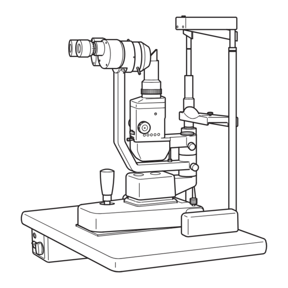
CONFIGURATION NAMES OF MAIN BODY COMPONENTS Chinrest jack Fixation target mounting holes 10 Eyepiece Forehead rest *1 Canthus marker Magnification changer lever Slit rotation control ring Slit width control knob Chinrest *1 Aperture and slit length control wheel Chinrest adjuster Filter selection lever Lamphouse cover Illumination arm... -
Page 12: Standard Accessories
STANDARD ACCESSORIES Make sure that all the following standard accessories are included. Figures in parentheses are the quantities. Some accessories are not included as standard depends on the model. Chinrest paper (1) Focusing test rod (1) Spare illumination lamp (1) Spare chinrest paper pin (2) Spare fuse (1) Brush (1) -
Page 13: Components
COMPONENTS COMPONENTS (1) Main unit (2) Instrument type table (w/power supply) (2)’ Unit type table (w/power supply) (3) Rail cover (4) Chinrest unit (5) Power cable Article name Q'ty (1) Main unit (2) Instrument type table (w/power supply) (2)' Unit type table (w/power supply) (3) Rail cover (4) Chinrest unit (5) Power cable... -
Page 14: Assembly Procedure
ASSEMBLY PROCEDURE ASSEMBLY PROCEDURE (1) Selecting Voltage and Fuse Display window Voltage selector Voltage selector Fuse holder Fuse holder [except for U.S.A. and Canada] [for U.S.A. and Canada] * Check the setting on the voltage selector, which is located on the bottom of the power supply. * If the selector does not match the outlet voltage, turn the selector to the proper setting with a screwdriver. - Page 15 (b) To secure the unit model table to the ophthalmic unit. Washer * Peel off the tape which secures the plastic washer to the mounting bracket's shaft. * Insert the shaft of the mounting bracket into the hole of the arm on the ophthalmic unit. The plastic washer should be between the mounting bracket and the arm.
- Page 16 (4) Mounting the Main Unit Tape Wheel Rail * Place the wheels of the base assembly evenly on the table rails. * After checking to see that the main unit moves smoothly on the rails, insert the rail covers in the space between the rail and table.
-
Page 17: Checking Procedure
(6) Installing the Chinrest Paper * Remove the two pins from the chinrest. * Place the pins through the holes in the chinrest paper. Remove the wrapping from the chin- rest paper. * Align the pins with the holes in the chinrest and secure the paper to the assembly. (7) Accessory Box * An accessory box is supplied to store the accessories. -
Page 18: Operation Procedures
OPERATION PROCEDURES PREPARATION-DIOPTER COMPENSATION AND INTERPUPILLARY DIS- TANCE ADJUSTMENT Before using the instrument, always carry out the diopter compensation and interpupillary dis- tance adjustments. (1) Use of the focusing test rod The focusing test rod which is a standard accessory, is used to establish the proper micro- scope settings for each use. -
Page 19: Patient Position
(4) Interpupillary distance adjustment While looking through the eyepieces at the image on the focusing test rod, adjust the converg- ing binocular's prism box, so that the image is fused and a stereo-scopic image results. For operator comfort, since each eyepiece can be moved independently, insure that both eye- pieces are at the same height. -
Page 20: Operation Of The Illumination Unit
(4) Locking the base To lock the base, tighten the base locking knob. (5) Focusing * Gross adjustment for alignment or focusing is done by the operation described in (1) * Fine adjustment for alignment or focusing should be done by the operations described in (2) and (3) above while looking through the microscope. -
Page 21: Troubleshooting
TROUBLESHOOTING TROUBLESHOOTING GUIDE If any problem should occur, first consult the following trouble shooting table, and follow the suggested instructions. Then, if the trouble is not corrected, contact your nearest TOPCON dealer. Trouble Possible Cause Remedy Refer to No illumination Power cable is not properly con- Connect cable to the outlet. -
Page 22: Specifications
SPECIFICATIONS MICROSCOPE Type Binocular stereoscopic microscope with erect image. Revolver type objective changing system provides two magnifi- Magnification changer cation changes. Objective 1× and 1.6× Eyepieces 10× and (16× option) Objectives × Eyepieces = Magnification Field of view 1× 10× 10×... - Page 23 Unit Table size 440mm × 350mm Subject to change in design and/or specifications without advance notice. Agency Compliance The SL-1E is designed to comply with the following agency standards: • IEC60601-1:2005 Ed3.0 • EN60601-1:2006/AC:2010 • IEC60601-1-2 Ed3.0:2007/EN60601-1-2:2007/AC:2010 • UL 60601-1: 2003 •...
-
Page 24: Environmental Conditions
ENVIRONMENTAL CONDITIONS ENVIRONMENTAL CONDITIONS FOR USE Temperature : 10°C - 40°C Humidity : 30% - 90% (without dew condensation) Air pressure : 700hPa - 1060hPa STORAGE CONDITIONS Environmental conditions (without package) Temperature : 10°C - 40°C Humidity : 10% - 95% (without dew condensation) Air pressure : 700hPa - 1060hPa ... -
Page 25: Electromagnetic Compatibility
Guidance and manufacturer's declaration - electromagnetic emissions The SL-1E is intended for use in the electromagnetic environment specified below. The customer or the user of the SL-1E should assure that it is used in such an environment. Emissions test Compliance... - Page 26 Guidance and manufacturer's declaration - electromagnetic immunity The SL-1E is intended for use in the electromagnetic environment specified below. The customer or the user of the SL-1E should assure that it is used in such an environment. IEC 60601 Compliance...
- Page 27 Guidance and manufacturer's declaration - electromagnetic immunity The SL-1E is intended for use in the electromagnetic environment specified below. The customer or the user of the SL-1E should assure that it is used in such an environment. IEC 60601 Compliance...
- Page 28 Recommended separation distance between portable and mobile RF communications equipment and the SL-1E The SL-1E is intended for use in an electromagnetic environment in which radiated RF dis- turbances are controlled. The customer or the user of the SL-1E can help prevent electro-...
-
Page 29: Optical Radiation Hazard
UV blocking intraocular lens or for the eyes of very young children. The value stated for an SL-1E gives a measure of hazard potential when the instrument is oper- ated at maximum intensity and maximum aperture. Values of L... -
Page 30: System Classification
SL-1E is the ordinary instrument (enclosed instrument without protection against ingress of water) Methods of sterilization or disinfection recommended by the manufacture: SL-1E do not have any part to be sterilized or disinfected. Not AP or APG equipment PURPOSE OF USE This instrument is used for the enlargement observation of eyeballs and the parts. -
Page 31: Shape Of Plug
SHAPE OF PLUG Country Voltage/frequency Shape of plug Mexico 110V/50Hz Type C&E Argentina 220V/60Hz Type A Peru 220V/60Hz Type A Venezuela 110V/50Hz Type C&E Bolivia & Paraguay 220V/60Hz Type A (Most common) Type H (Infrequently) Chile 220V/60Hz Type A Colombia 110V/50Hz Type C Brazil... -
Page 32: Maintenance
MAINTENANCE DAILY CARE * Remove dust from the instrument except the lenses and prisms, using a dry soft cloth at reg- ular intervals. * This instrument may be adversely affected by dust. Use the dust cover when not in use. REPLACING THE FUSE To avoid electric shock, unplug the power cord from the grounded out- WARNING... -
Page 33: Replacing The Illumination Lamp
REPLACING THE ILLUMINATION LAMP To avoid electric shock, do not touch the external connection terminal CAUTION and the patient at the same time. When replacing the lamp, use care as the metal components inside the housing can become extremely hot. The suggested procedure is as follows: * After turning the power switch OFF, loosen the lamphouse cover clamping screw to remove the lamphouse cover. -
Page 34: Cleaning
CLEANING (1) Cleaning the lens and mirror If any dust settles on the lens or mirror, remove it as follows: Use the cleaning brush, which is included in the standard accessories, to remove the dust. In case any dust still remains, wipe it off using a soft cotton cloth moistened with a little alcohol. Never use your finger or any hard object for cleaning. -
Page 35: Ordering Supplies
ORDERING SUPPLIES To order the following replacement parts, be sure to specify the product name, part number and quantity required. Product name Part number Appearance Illumination lamp 40340 20700 Socket 44615 20100 Chinrest paper 40310 40820 Fuse F1, F2: T1AL 250V (100, 120V) 44635 60030 T500mAL 250V (220, 240V) 44635 60040... -
Page 36: Optional Accessories
OPTIONAL ACCESSORIES To avoid electric shock, do not touch the external connection terminal CAUTION and the patient at the same time. FIXATION TARGET Target for the fixation of patient's eyes. * The fixation device can be installed on either side of the chinrest. * Insert the fixation target into either of the two mounting holes and then remove the cap to insert the fixation target plug into the chinrest jack. -
Page 37: Hruby Lens
HRUBY LENS Used for observation of the fundus and posterior segment of the vitreous body. In routine applications, only the anterior segment of the vitreous body can be examined because of the refraction effects of the cornea and crystalline lens. However, with the Hruby Lens, examination of the fundus and the posterior segment of the vitreous body is possible. -
Page 38: 10×Measuring Eyepiece
10×MEASURING EYEPIECE Use this accessory eyepiece in place of the normal eyepiece for measurements of both the size and angle. The measuring eyepiece is extremely helpful when fitting toric contact lenses: Specifications Scales Linear Scale: 16mm; minimum 0.5mm, increments to be used at 10×magnification Angle Scale: 360°;... -
Page 39: Accessory Drawer
ACCESSORY DRAWER For storing the focusing test rod and other accessories. APPLANATION TONOMETER Haag-Streit AG Model R900 can be used. AUTOMATIC INSTRUMENT TABLE AIT-15 Specifications • Dimensions ......510(W)×450(D)mm • Table height......600~820mm • Table size ......490×500mm • Weight ......approx. 23kg • Power consumption..270VA •... - Page 41 When contacting us, please have the following information at hand re your unit: Machine type: SL-1E Manufacturing No. (Displayed on the rating plate on the left of the base.) Period of Usage (i. e. the purchase date).
- Page 42 SLIT LAMP SL-1E 44615 95997 Printed in Japan 1106-100TH...
Need help?
Do you have a question about the SL-1E and is the answer not in the manual?
Questions and answers