
Related Manuals for Simpli Home WyndenHall brooklyn + max AXCAMH72-BL


Summary of Contents for Simpli Home WyndenHall brooklyn + max AXCAMH72-BL
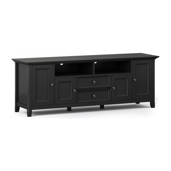
- Page 1 S IMP HOME ® AMHERST / HALIFAX / WASHINGTON 72 INCH WIDE TV MEDIA STAND MODEL # AXCAMH72-BL...
- Page 2 S IMP HOME ® Questions, problems, assembly help, missing parts? No need to return the product, we will gladly help and ship your replacement parts free of charge Please call Customer Service at 1-866-518-0120 ext. 262 Monday to Friday between 9 am –4 pm EST or go to www.simpli-home.com/parts request In order to assist you in a timely manner, please have the following...
-
Page 3: Safety Information
IMPORTANT : Please read this manual carefully before beginning assembly of this product. Keep this manual for future reference. SAFETY INFORMATION CAUTION: Injuries and damage can occur from furniture tip over if product is not properly anchored to the wall. Use the Furniture Anti-Tipping Restraint provided with the product. -
Page 4: Care And Maintenance
IMPORTANT : Please read this manual carefully before beginning assembly of this product. Keep this manual for future reference. CARE and MAINTENANCE Perhaps the greatest environmental damage to wood furniture comes from wide swings in relative humidity (RH) in our homes. Wood absorbs and desorbs water as relative humidity rises and falls, and in doing so it swells and shrinks. -
Page 5: Pre-Assembly Information
PRE-ASSEMBLY INFORMATION MODEL # AXCAMH72-BL PART DESCRIPTION LEFT SIDE RIGHT SIDE QTY 1 QTY 1 QTY 1 CENTRE SHELF BOTTOM SHELF TOP SHELF QTY 1 QTY 1 QTY 1 TOP DIVIDER LEFT MIDDLE DIVIDER RIGHT MIDDLE DIVIDER QTY 1 QTY 1 QTY 1 NEED HELP? For help with assembly or if you are missing a part, Please call customer service at 1-866-518-0120 ext. - Page 6 PRE-ASSEMBLY INFORMATION MODEL # AXCAMH72-BL PART DESCRIPTION LEFT DIVIDER RIGHT DIVIDER SHELF QTY 1 QTY 1 QTY 2 LEFT BACK PANEL LARGE DOOR (L&R Same) SMALL DOOR (L&R Same) QTY 1 QTY 2 QTY 2 Warning Label RIGHT BACK PANEL BOTTOM BACK PANEL TOP BACK PANEL QTY 1...
- Page 7 PRE-ASSEMBLY INFORMATION MODEL # AXCAMH72-BL PART DESCRIPTION BOTTOM SUPPORT LEG FLIP DOWN DOOR DRAWER FRONT QTY 2 QTY 1 QTY 1 DRAWER BACK LEFT DRAWER SIDE RIGHT DRAWER SIDE QTY 1 QTY 1 QTY 1 DRAWER BOTTOM QTY 1 NEED HELP? For help with assembly or if you are missing a part, Please call customer service at 1-866-518-0120 ext.
- Page 8 PRE-ASSEMBLY INFORMATION MODEL # AXCAMH72-BL HARDWARE DESCRIPTION CAM LOCK PIN WOOD DOWEL ALLEN KEY SCREW CAM LOCK M6 X 30mm ALLEN KEY Ø8 X 30mm QTY 22 SETS QTY 34 QTY 1 QTY 22 PHILLIPS SCREW HANDLE ROUND HEAD M4 X 25 mm M4 X 15mm SHELF SUPPORT MAGNET AND PLATE...
- Page 9 COMPONENTS-KEY DIAGRAM MODEL # AXCAMH72-BL...
- Page 10 ASSEMBLY MODEL # AXCAMH72-BL STEP-1 1. Attach four Cam Lock Pins 2 into pre-drilled holes on back of Drawer Front O . 2. Use Phillips screwdriver to secure Cam Lock Pins. Do not over-tighten. STEP-2 PL ,PR t o D r a w e r F r o n t O . PL , PR .
- Page 11 ASSEMBLY MODEL # AXCAMH72-BL STEP-3 STEP-4 1. Align Drawer Back Q with Drawer Bottom R and press firmly into slot . 2. Attach Drawer Back using two Allen Key Screws 1 through guide holes on each Drawer Side PL , PR . 3.
- Page 12 ASSEMBLY MODEL # AXCAMH72-BL STEP-6 1. Insert six Dowels 3 into guide holes on Centre Shelf E . 2. Use rubber mallet to tap Dowels 3 into bottom of holes securely. 1/2 length of Dowels should be exposed. 3. Attach Hinge 10 to Centre Shelf E by using Phillips Screws 11 to attach Centre Shelf E through guide holes.
- Page 13 ASSEMBLY MODEL # AXCAMH72-BL STEP-8 1. Align Wood Dowels with guide holes and attach Centre Shelf E to Dividers GL , GR .
- Page 14 ASSEMBLY MODEL # AXCAMH72-BL STEP-9 1. Attach six Cam Lock Pins 2 into pre-drilled holes on Top Shelf D . 2. Use Phillips screwdriver to secure Cam Lock Pins. Do not over-tighten. STEP-10 1. Use three Allen Key Screws 1 to attach Top Divider F through guide holes from Top Shelf D to pre-drilled holes of Top Divider F .
- Page 15 ASSEMBLY MODEL # AXCAMH72-BL STEP-11 1. Align Cam Lock Pin with guide holes on Middle Dividers GL , GR and attach Middle Dividers GL , GR to Top Shelf D . 2. Insert six Cam Locks 2 into guide holes on Middle Dividers GL , GR (3 Cam Locks on each Middle Divider ).
- Page 16 ASSEMBLY MODEL # AXCAMH72-BL STEP-12 1. Insert two Dowels 3 into guide holes on each Divider HL , HR . 2. Use rubber mallet to tap Dowels 3 into bottom of holes securely. 1/2 length of Dowels should be exposed. 3.
- Page 17 ASSEMBLY MODEL # AXCAMH72-BL STEP-14 1. Align Cam Lock Pins with guide holes on Top Shelf D and attach Dividers HL , HR to Top Shelf D . 2. Insert six Cam Locks 2 into guide holes on Top Shelf D . 3.
- Page 18 ASSEMBLY MODEL # AXCAMH72-BL STEP-15 1. Align Wood Dowels with guide holes on Bottom Shelf C and attach parts HL , HR , GL , GR to Bottom Shelf C . 2. Use three Allen Key Screws 1 to attach each part HL , HR , GL , GR through guide holes from Bottom Shelf C to pre-drilled holes of parts HL , HR , GL , GR .
- Page 19 ASSEMBLY MODEL # AXCAMH72-BL STEP-16 1. Insert two Dowels 3 into guide holes on each Side BL , BR . 2. Use rubber mallet to tap Dowels 3 into bottom of holes securely. 1/2 length of Dowels should be exposed. 3.
- Page 20 ASSEMBLY MODEL # AXCAMH72-BL STEP-17 1. Align Wood Dowels and Cam Lock Pins with guide holes on Bottom Shelf C and attach Sides BL , BR to Bottom Shelf C . 2. Insert six Cam Locks 2 into guide holes on Bottom Shelf C . 3.
- Page 21 ASSEMBLY MODEL # AXCAMH72-BL STEP-18 1. Align Wood Dowels with guide holes on Top A and attach parts BL , BR , HL , HR , F to Top A . 2. Use three Allen Key Screws 1 to attach each part BL , BR , HL , HR , F through guide holes each part BL , BR , HL , HR , F to pre-drilled holes of Top A .
- Page 22 ASSEMBLY MODEL # AXCAMH72-BL STEP-19 1. Align two Bottom Support Legs M with pre-drilled holes on back of Bottom Shelf C . Use Phillips Screwdriver to tighten four Phillips Screws 16 .
- Page 23 ASSEMBLY MODEL # AXCAMH72-BL STEP-20 Warning Label Note: 1. Attach the Back Panels LL , LR , L1 , L2 to back frame using Phillips Screws Round Head 5 through guide holes from Back Panels. 2. Use Phillips Screwdriver to tighten screws. Do not over-tighten.
- Page 24 ASSEMBLY MODEL # AXCAMH72-BL STEP-21 1. Attach Adjustable Hinges 14 to Doors J , K using Phillips Screws 15 into pre-drilled holes on Doors J , K . STEP-22 1. Attach Adjustable Hinges 14 on Doors J , K to parts BL , BR , HL , HR using Phillips Screws 15 into pre-drilled holes on parts BL , BR , HL , HR .
- Page 25 ASSEMBLY MODEL # AXCAMH72-BL STEP-23...
-
Page 26: Important Note
ASSEMBLY MODEL # AXCAMH72-BL IMPORTANT NOTE: Tighten the Screw marked II to fasten hinge. The door may need to be adjusted so that all the spaces between the door and the unit sides are equal. To adjust, follow instructions: 1. Side adjustment 4 mm To move the door towards the side panel, loosen screw I and tighten screw II . - Page 27 ASSEMBLY MODEL # AXCAMH72-BL STEP-24 shelf level 1 shelf support anti - tipping shelf level 2 shelf level 3 1. Use four Shelf Supports 6 for each Cabinet Shelf I in desired location . 2. Two Shelf Supports 6 may be used on back top of each Cabinet Shelf I as a tipping restraint.
- Page 28 ASSEMBLY MODEL # AXCAMH72-BL STEP-25 1. Insert assembled drawer into glides on assembled TV.
- Page 29 FURNITURE TIP OVER RESTRAINT ASSEMBLY WARNING Serious or fatal crushing injuries can occur from furniture tip-over. If the furniture tip over restraint kit is not in the box, please contact our customer service department in order to obtain another kit before using the furniture. STEP-26 NOTE: The screwdriver is not included in the hardware pack.
- Page 30 FURNITURE TIP OVER RESTRAINT ASSEMBLY Furniture Tip Over Restraint Instructions: Attach one of the mounting brackets securely to the back edge of the furniture. Use the shorter screw. Determine where furniture is to be placed and mark location on the wall for mounting bracket screw hole approximately 2 inches below the bracket mounted to the furniture.
-
Page 31: Warranty
S IMP HOME ® WARRANTY Thank you for purchasing a Simpli Home – Wyndenhall – Brooklyn + Max product. These products have been made to demanding, high-quality standards and are guaranteed for domestic use against manufacturing faults for a period of 12 months from the date of purchase. This warranty does not affect your statutory rights.
Need help?
Do you have a question about the WyndenHall brooklyn + max AXCAMH72-BL and is the answer not in the manual?
Questions and answers