
Subscribe to Our Youtube Channel
Related Manuals for Bauer FAN Separator PSS 1.1-300


Summary of Contents for Bauer FAN Separator PSS 1.1-300
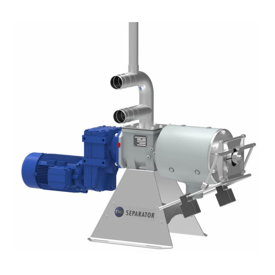
- Page 1 ORIGINAL OPERATING MANUAL FAN PRESS SCREW SEPARATOR PSS 1.1-300 Version: II- 2019...
- Page 3 Thank you for buying a FAN PRESS SCREW SEPARATOR! This operating manual is an important document that describes the operation and maintenance of the FAN PRESS SCREW SEPARATOR. All information contained in this manual is based on the latest product details available at the time of printing.
- Page 4 PRODUCT DETAILS Type designation: Press Screw Separator PSS 1.1-300 Type number: Serial number Dealer: Name: Address: Tel. / fax: Shipping date: FAN Separator GmbH Producer of the machine: Bernecker Straße 5 D-95509 Marktschorgast/Germany Tel: +49/9227/938-400 Fax: +49/9227/938-444 Email: info@fan-separator.de www.fan-separator.de Owner or operator: Name: Address:...
-
Page 5: Table Of Contents
TABLE OF CONTENTS GENERAL SAFETY INSTRUCTIONS ....................... 1 Warnings and Symbols ..........................1 Duty to Furnish Information ..........................1 Product Liability .............................. 1 Qualified Operators ............................2 Intended Use ..............................2 Unauthorized Modification and Manufacture of Replacement Parts .............. 2 Disposal ................................ - Page 6 13 MAINTENANCE AND INSPECTION ........................ 21 13.1 Gearbox and Motor ..........................21 13.1.1 Supply of Sealing Medium ........................21 13.1.2 Sealing ..............................22 13.2 Inspection of the screen and the Guide Rails ..................23 13.3 Inspecting and Reinstalling the screen ....................25 13.4 Inspecting and Reinstalling the auger ......................
-
Page 7: General Safety Instructions
1 GENERAL SAFETY INSTRUCTIONS This operating manual contains important information that must be observed during setup, operation and maintenance. For this reason, it must always be read and observed very carefully by the installation technician as well as the qualified personnel. It must always be available at the usage location of the machine. -
Page 8: Qualified Operators
1.4 QUALIFIED OPERATORS These are persons who on behalf of their training, experience and instruction as well as their knowledge of relevant standards, rules, precautions to be taken for accident prevention and prevailing operating conditions have been authorized by the person in charge of system safety to perform the respective tasks required and in doing so are able to recognize and avoid potential hazards. -
Page 9: General Instructions For Safety And Accident Prevention
GENERAL INSTRUCTIONS FOR SAFETY AND ACCIDENT PREVENTION Check the operational safety of the machine before every start ! WARNING All regulations of public authorities that apply to the operation and maintenance of the system must be strictly observed. In addition to the operating manual, all generally applicable statutory and otherwise mandatory regulations on accident prevention and environmental protection must be separately prescribed and observed. - Page 10 Procedures for switching the machine on and off as well as inspection of the control indicators must be car- ried out as described in the operating manual. Before switching on or starting up the machine, it must be ensured that no one will be endangered by the starting up of the machine.
- Page 11 Do not start the machine unless all guards and safety devices are mounted completely and in proper working position! Protective caps and covers may not be removed. The stickers affixed to the device with safety and warning signs provide important instructions for safe opera- tion;...
-
Page 12: Function Description
3 FUNCTION DESCRIPTION The FAN press screw separator serves for separating pumpable slurry (solid-liquid mixtures with rela- tively low solid matter content and no foreign bodies such as metal parts, stones, wood or rags) into sol- id and liquid (thin slurry) fractions. As a compact device, it combines the functions of two separators, specifically the functions of a screen and a press. -
Page 13: Setup Of The Separator
Overflow Distribution of the Liquid solid phase Distribution of the phase liquid phase Inflow Distribution of the via BAUER liquid phase slurry injector Sale of the solid via BAUER Cerres phase Pivot or Rainstar Separator PSS 1.1-300 Composting of... -
Page 14: Features, Identification And Information
4.4 FEATURES, IDENTIFICATION AND INFORMATION To make it easier for you to familiarize yourself with your new FAN press screw separator, Fig. 4-2 shows you a longitudinal section of the internal machine design. We assist every customer in optimally selecting the right main separator components for the specific application before it is purchased, manufactured, assembled and shipped. -
Page 15: Type Plates - Information Signs
4.5 TYPE PLATES - INFORMATION SIGNS When you contact your dealer or communicate directly with FAN Separator GmbH about wearing parts or for technical support for your press screw separator, you will be asked for your serial number and machine number in order to ensure faster and more effective assistance. The type, year of manufacture and serial number of the separator is indicated on the type plate riveted to the screen housing near the inflow. -
Page 16: Setup And Assembly
4.7 SETUP AND ASSEMBLY The basic dimensions of the FAN Press screw separator for determining the dimensions of the setup location are shown in Fig. 4-3. The Separator PSS 1.1-300 has a dead weight of approx. 220 kg. [mm ] 1018 1289 Ø89... -
Page 17: Complete System
4.8 COMPLETE SYSTEM The complete system of the press / screw separator also includes the material supply and discharge handling. The incoming material can be delivered by pump or from an elevated tank by means of gravity. Because the pump delivery rate cannot be precisely determined, an overflow is absolutely required in order to protect the separator from an overload. -
Page 18: Inflow Setup
A tube of DN90 is required for this. Fig. 4-8 Drainage line If no FAN/BAUER pump is installed, the pump for supplying the separator should have a NOTE pump rate of at least 15 m³/h since the capacity of the separator otherwise cannot be fully utilized. -
Page 19: Electrical Connection
5 ELECTRICAL CONNECTION The electric motor is equipped with a terminal strip. Like all electrical connections, the external motor control must be connected properly by a qualified electrician. DANGER Work on electrical and electronic components of the system may only be per- formed by a trained electrician or otherwise appropriately trained personnel under the guidance and supervision of a trained electrician in accordance with the appli- cable electrical and electronic regulations. -
Page 20: Setup And Operation Of The Motor
5.1 SETUP AND OPERATION OF THE MOTOR The motors in the standard design are suitable for operation up to a maximum ambient temperature of +40 °C (104 °F) as well as an elevation of up to 1000 m above sea level. Conditions of high humidity (e.g. -
Page 21: Preparation For Initial Startup
6 PREPARATION FOR INITIAL STARTUP Before beginning the startup process, check the following measures: 1. The separator must be firmly anchored to the ground. 2. Make sure that the mouth piece and the functioning of the separator can be seen clearly from the switch cabinet [it must be possible to watch the solid cake and its discharge speed]. -
Page 22: Solid Cake Formation
NOTE The reaction time before each setting change takes several minutes, meaning that the effect of any change can only be determined after this time. For this reason, always allow enough time after making a change and only make changes in small steps! NOTE Before the initial startup and after prolonged downtime, the separator should be flooded before switching it on by starting the pump briefly in order to prevent possible damage... -
Page 23: Configuration To Stabilize The Solid Cake
Depending on the dry matter content (DM content) of the input medium, the solid cake will either already have the correct consistency with the initial setting of the weights or it will be either too soft or too firm. After formation of a cake and roughly 20 cm of DM throughput, the base settings should be corrected “... -
Page 24: Additional Instructions For Flawless Operation
ADDITIONAL INSTRUCTIONS FOR FLAWLESS OPERATION Make certain that the overflow does not produce a siphon effect. This would produce unfavorable flows with too little solid matter entering the separator, lowering the throughput while also interfering with the self-cleaning of the screen, which is activated by the solid mat- ter. -
Page 25: Test For Separation Capability
9 TEST FOR SEPARATION CAPABILITY In order to test the separation capability of the medium supplied to the separator, you can perform a simple suitability test. Take some of the medium intended for separation into your hand and try to press it out. -
Page 26: Important Aspects To Be Considered During Operation
11 IMPORTANT ASPECTS TO BE CONSIDERED DURING OPERATION “ ” Check the output of the pump to ensure that the overflow bypass is only half full. Inspect the pump to ensure that the operating pressure on the seal of the auger drive does not exceed 2 m water column. -
Page 27: Maintenance And Inspection
13 MAINTENANCE AND INSPECTION 13.1 GEARBOX AND MOTOR The gearbox and motor are delivered ready for operation. They are filled with the required volume of oil and maintenance-free. After approx. 10,000 operating hours, but no later than every 2 years, the oil must be changed and the bearing inspected;... -
Page 28: Sealing
13.1.2 Sealing rotary shaft seal bushing wear plate The sealing consists of a rotary shaft seal running on the bushing which is glued on the auger hub. In addi- tion a slide ring pretensioned by O-rings is mounted on the auger hub. This slide ring serves as additional protection for the rotary shaft seal. -
Page 29: Inspection Of The Screen And The Guide Rails
13.2 INSPECTION OF THE SCREEN AND THE GUIDE RAILS The screen and the guide rails must generally be inspected every 1 to 3 months depending on the sepa- ration medium. For this inspection, the screen must be removed, cleaned with a high-pressure cleaner and then checked for damage and traces of wear. - Page 30 The plastic profile rails serve to dampen the impact shocks of the separator on the screen guide rails and reduce friction. “ ” “ ” The screen floats breathes ] in the guide rails, depending on how hard the solid cake is. The slight up “...
-
Page 31: Inspecting And Reinstalling The Screen
13.3 INSPECTING AND REINSTALLING THE SCREEN The wearing of the screen occurs primarily in the area where the auger blades end in the screen, i.e. at the transition to the pressing area of the separator. If a sharp-edged transition can be seen in this area (Fig. -
Page 32: Inspecting And Reinstalling The Auger
13.4 INSPECTING AND REINSTALLING THE AUGER The auger is made of stainless steel. In the area of the screen, the auger blades have been plated with a special material according to a special process, see Fig. 13-12. Inspect the auger for any damage and clean it. -
Page 33: Evaluation Criteria For The Auger And Screen With Regard To Wear And Recoating
13.5 EVALUATION CRITERIA FOR THE AUGER AND SCREEN WITH REGARD TO WEAR AND RECOATING All moving parts on the separator are subject to some amount of wear. Some of the parts that are direct- ly subject to wear and must therefore be inspected regularly have already been described. Good regular inspections and maintenance of the wearing parts will significantly lengthen the service life of the parts. -
Page 34: Summary Of Maintenance And Inspection Intervals
For example, Fig. 13-16, right and middle images, shows plating that has been worn down on the outer edges of the auger, but recoating is still possible because the plating on the face side is still retained up to 20%, meaning that the actual auger blade has not yet been damaged. Excluding the plating, the au- ger blades have a thickness in this area of 10 mm, meaning that the remaining plating can be deter- mined very precisely with a depth caliper. -
Page 35: Problems - Troubleshooting
14 PROBLEMS - TROUBLESHOOTING Troubleshooting should only be performed by appropriately qualified personnel. WARNING “ ” It is very important for you to familiarize yourself with the normal operating condition of the separator “ ” during your application. Normal includes the discharge speed in direct connection with the desired DM content of the solid cake. -
Page 36: Troubleshooting
14.2 TROUBLESHOOTING Fault Cause Remedy 1. Check: Switch cabinet and overflow 1. The material supply has been in- No solids are produced line. terrupted: Inspect and start the pump. The pump is off No liquid is discharged Clean the lines. - Page 37 Fault Cause Remedy The leverage of the weights is too Reduce the leverage; if the contact Solid cake is very hard; great, meaning that the contact force is too high, the screen could Solid matter comes out slowly pressure of the output regulator is be destroyed.
- Page 38 Remedy Fault Cause Replacement of the block- ing seal The pump is a high-pressure pump Replace the pump with a low- and/or the supply medium is highly pressure pump. Despite the supply of sealing abrading. medium (see section Mainte- The blocking seal has been worn The blocking seal must be re- nance and Inspection under out by the duration of operation.
-
Page 39: Accessories
15 ACCESSORIES 15.1 SEPARATOR CONTROL ANGER The connection of the switch cabinet to the electrical supply and the connection of the separator motor to the switch cabinet must be performed by an electrical ex- pert. The cable dimensions and the preliminary fuse must correspond to the power specifications. -
Page 40: Notes
16 NOTES Operating Manual for FAN Press Screw Separator PSS 1.1-300... -
Page 41: Conformity Declaration
17 CONFORMITY DECLARATION EC Conformity Declaration according to EC Directive 2006/42/EC The manufacturer FAN Separator Gesellschaft m.b.H. Bernecker Straße 5, D-95509 Marktschorgast, Germany Tel.: +49 9227 938-400; Fax: +49 9227 938-444 declares that the machine named below Machine designation FAN Press Screw Separator Machine type / base device PSS 1.1-300 correspondingly applies to the relevant provisions of the following directives.
Need help?
Do you have a question about the FAN Separator PSS 1.1-300 and is the answer not in the manual?
Questions and answers