Advertisement
Quick Links
Advertisement

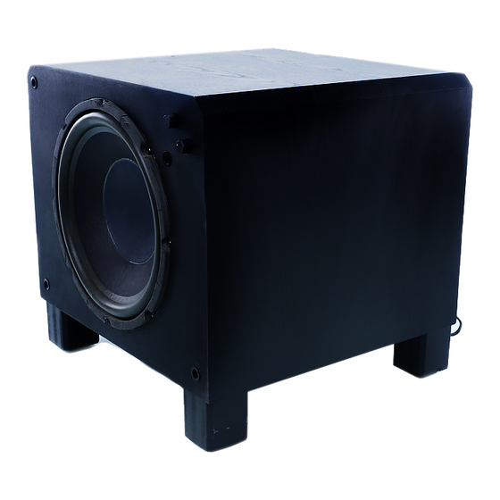
Summary of Contents for Velodyne SERVO 1200
- Page 1 Velodyne OWNER'S MANUAL Servo 1200 Subwoofer System...
-
Page 2: Safety Instructions
CAUTION: To reduce the risk of electric shock, do not remove cover (or back). No user-serviceable parts inside servicing to qualified service personnel. The lightning flash with arrowhead symbol, within an equilateral triangle, is intended to alert the user to the presence of uninsulated "dangerous voltage"... -
Page 3: Installation
High Pass Crossover. Because your satellite speakers cannot reproduce bass as accurately as the Servo 1200, optimum system performance is attained by rolling off the low end response of your satellites. The Servo 1200 is equipped with a high pass crossover for this purpose. To use the satellites from the Servo 1200's outputs. - Page 4 INSTALLATION OF SERVO 1200 USING FROM AMPLIFIER INPUTS Figure 1 shows how to connect your Servo 1200 to a receiver or integrated amplifier. When using the speaker level terminals, note the right and left channel designations above the terminals. Red speaker jacks are positive,...
- Page 5 LINE IN jack on the Servo 1200. Leave the unused input a'nd both outputs disconnected.
- Page 6 USING EXTERNAL CROSSOVER Velodyne offers an optional external LINE IN/OUT but must locate their Servo 1200 away from system electronics. By installing the external crossover near your electronics all leads between your pre-amp and power amp are kept as short as possible quency integrity is thereby maintained while enabling remote subwoofer installation (see Figure 3).
- Page 7 INSTALLATION OF TWO Although a single Servo 1200 will improve the performance of any additional power and effect of stereo Servo 1200s. Figure 4 shows stereo connection using speaker level inputs. Note that one pair of input/output terminals remain unused on each unit. Stereo connections can also be made with the line level inputs.
- Page 8 The control panel on the front of your Servo 1200 includes a power switch, a power-on indicator lamp, and a level control.
- Page 9 Your Servo 1200 is equipped with a special ciruit designed to protect the unit from damage. Either of the two conditions below will power the unit down and keep it off for 5 seconds after the fault is corrected.
- Page 10 low frequencies. Even at 1 watt drive levels, many loudspeakers have 8 to 10% THO at 40 Hz. With the 50 watt drive levels needed to produce realistic bass intensity, these distortion figures rise to astonishing levels. Second the distortion products produced by a nonlinear woofer are much easier to hear than is the fundamental fre quency.
- Page 11 OR SPEAKERS Figure 5: Servo Series System Block Diagram Power Amplifier. The Servo 1200's amplifier must provide power for distortion correction as well as basic music reproduction. Custom Driver. Although our HGS electronics play the most important role in reducing distortion, the Servo Series driver must be carefully engineered and constructed so as not to undo the work that the HGS electronics have done.
- Page 12 VELODYNE SERVO SUBWOOFER SYSTEM SPECIFICATIONS Type: Power: Stereo Input: Diameter: Linear travel: Voice Coil: Magnet: Cone: Accelerometer: High Pass: Low Pass: Finish: Dimensions: Volume: Weight: Grill: Servo Loop Gain: Servo Loop Feedback Rate: Maximum Distortion (25 Hz @ 104 dB): Frequency Response: Driver Resonant Frequency: Damping...


Need help?
Do you have a question about the SERVO 1200 and is the answer not in the manual?
Questions and answers