Table of Contents
Advertisement
Quick Links
Advertisement
Table of Contents

Related Manuals for Velodyne DIGITAL DRIVE SERIES


Summary of Contents for Velodyne DIGITAL DRIVE SERIES
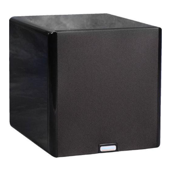
- Page 1 USER’S MANUAL SERIES Featuring Software Version 2.2.0...
- Page 2 Enjoy. Thank you for choosing a Velodyne. Our passion for high performance, low-distortion bass is the driving force behind our worldwide reputation in audio and technical innovation. We are pleased to bring the Velodyne sound experience to your home.
- Page 3 Digital Drive Series User’s Manual - i...
-
Page 5: Table Of Contents
Appendix c: Important Subwoofer Information ......46 www.VelOdyne.cOm Digital Drive Series User’s Manual - ii... -
Page 7: Congratulations
Regardless of where you install your Velodyne subwoofer, it must remain in an upright position (woofer facing forward). Using, shipping, or otherwise storing the subwoofer in any other position for an extended period of time may result in damage to the unit not covered by warranty. -
Page 8: Package Contents
PACkAGE CONTENTS your Velodyne digital drive Subwoofer consists of the following components: • Digital Drive Subwoofer • Power Cord • Remote Control • Digital Drive Accessory Kit, consisting of: - calibrated precision microphone - microphone windscreen cover - Tabletop microphone stand... -
Page 9: Remote Control
- daisy chain feature REMOTE CONTROL The Velodyne digital drive infrared remote control allows you to set up, adjust, and reset your subwoofer when connected to a television or a video monitor. you will also use your remote to activate preset listening values, set the subwoofer’s volume up or down, mute the subwoofer, or set a night operational mode. -
Page 10: Remote Control Buttons
VOL (+/-) – Raises or lowers the volume of your subwoofer. • The blue (Velodyne) light flashes more quickly as the volume increases, and the light blinksout the volume level after you stop adjusting it. For example, for a volume of 34, you would see three long blinks followed by four shorter ones. -
Page 11: Digital Drive Accessory Kit
SUBWOOFER CONTROLS ANd PORTS The Velodyne Digital Drive subwoofer is set up, configured, and adjusted by the controls, inputs, and connections located on the rear panel of the unit. Figure 2 shows the location of each of these important operational interfaces. - Page 12 EQ VIdEO OUTPUT – Used to display the video generated by the subwoofer. S-Video or composite connections are available (composite cable included). nOTe: Only connect to a single video output at a time. 6 - Digital Drive Series User’s Manual www.velodyne.com...
- Page 13 (14) SPEAkER LEVEL INPUT RIGHT/LEFT – This speaker-level connector allows either banana plug/ jack or exposed wire/terminal connections. www.velodyne.com Digital Drive Series User’s Manual - 7...
-
Page 14: Installation Quick Start
5. The unit should emit 25 “sweep” tones then restart and play normally. The subwoofer has now automatically eQ’d itself to your room. 6. Adjust the subwoofer’s volume to taste. 7. enjoy! 8 - Digital Drive Series User’s Manual www.velodyne.com... -
Page 15: Installation Step-By-Step
A Word About Subwoofer Outputs The Velodyne subwoofer is designed to operate using the full range audio signal for input when using the digital built-in crossover. Most processors/receivers have a “subwoofer out” jack that is internally filtered and designed to be used with a conventional amplifier and speaker. -
Page 16: A Word About Interconnect Cables
“mouse extension” serial cable (available at any computer store, from your Authorized Velodyne dealer, or from Velodyne directly) and connect the RS-232 OUT port of the primary sub to the RS-232 In port of the secondary sub. Then, all runtime commands directed at the primary sub (such as volume) will be communicated to the secondary sub automatically through the serial cable. -
Page 17: Subwoofer Performance
THX™ standard. If you use this “small” speaker set up recommendation go into the DD’s “SYSTEM SETTINGS” screen and turn the dd’s crossover “OFF” (see page 26). www.velodyne.com Digital Drive Series User’s Manual - 11... -
Page 18: Subwoofer Setup - Overview
SelecT button. Following is an overview of the screens you will be using to set up your Velodyne digital drive subwoofer. 12 - Digital Drive Series User’s Manual... - Page 19 Setup screen, as shown in Figure 4. HINT: You do not need to press MENU to begin entering the setup code. You can begin the 12345 sequence by pressing the number 1 on the remote. www.velodyne.com Digital Drive Series User’s Manual - 13...
- Page 20 EQ you desire. Each preset can have its own eQ settings. By navigating the cursor to the NEXT field and pressing SELECT, the following screen appears: 14 - Digital Drive Series User’s Manual www.velodyne.com...
- Page 21 Subsonic Filter Frequency and Slope – Set your subwoofer’s subsonic filter (low frequency limit), in • increments of 1, between 15Hz – 35Hz and slope at 6, 12, 18, 24, 30, 36, 42 and 48 dB/octave. www.velodyne.com Digital Drive Series User’s Manual - 15...
- Page 22 • Light Control – This setting determines the status of the Velodyne logo light. The setting defaults to “on.” 16 - Digital Drive Series User’s Manual...
-
Page 23: Onscreen Programming And Setup - Step By Step
5. Set the video input where you connected the video output as the active TV image. Theintroductory screen with the Velodyne logo and “Velodyne digital drive” should now appear on your TV screen, as follows: www.velodyne.com... - Page 24 6. Press menU and enter 12345 to enter the eQ setup screen, as follows: 18 - Digital Drive Series User’s Manual www.velodyne.com...
- Page 25 Upon pressing 5, you should see the following screen: www.velodyne.com Digital Drive Series User’s Manual - 19...
- Page 26 ReSPOnSe” graph on your TV shows the response of your full range speakers (the right hand portion of the graph) at approximately 76 dB (or a comfortable listening level). This is shown below: 20 - Digital Drive Series User’s Manual www.velodyne.com...
- Page 27 That is, the “SySTem ReSPOnSe” graph should be relatively flat (although at this point there will be peaks and valleys that will be addressed next). The screen should now look something like this: www.velodyne.com Digital Drive Series User’s Manual - 21...
- Page 28 The worst location for a subwoofer is typically far away from any walls, and close to the center of your room. Avoid these locations when possible. when using a pair of Velodyne subwoofers in stereo, it is preferable to place each subwoofer by the satellite of the same channel.
- Page 29 You are now ready to adjust the crossover, subsonic filter, volume, and phase controls of your DD unit. NOTE: if the remote seems intermittent or unresponsive, be sure you are pointing it at the subwoofer and not your TV! www.velodyne.com Digital Drive Series User’s Manual - 23...
- Page 30 An example of a crossover changed to 100Hz is shown below: 24 - Digital Drive Series User’s Manual www.velodyne.com...
- Page 31 TIP: To see immediate feedback on the effects of your changes to the “SYSTEM RESPONSE” graph, press the TeST button. The following screen appears: Press TEST again to return to the SYSTEM SETTINGS screen. www.velodyne.com Digital Drive Series User’s Manual - 25...
- Page 32 If this is the case, you will want to defeat the subwoofer’s low pass crossover. To defeat the low pass crossover, press the SelecT key, then the ReSeT key. The following screen appears: 26 - Digital Drive Series User’s Manual www.velodyne.com...
- Page 33 (since this is the point where both the subwoofer and the speakers are playing the same audio information). Don’t be afraid to experiment to find the perfect match between your subwoofer and main speakers! www.velodyne.com Digital Drive Series User’s Manual - 27...
- Page 34 The AUTO eQ proceeds until you either save settings, press SelecT to return to manual eQ, move the cursor off the AUTO EQ field (in which case the field automatically reverts to MANUAL), or 50 sweeps have occurred. 28 - Digital Drive Series User’s Manual www.velodyne.com...
- Page 35 “SySTem ReSPOnSe” graph), simply navigate the cursor to the eQ that corresponds to 40Hz and use the UP or DOWN arrow keys to “slide” the EQ up or down. An example of this is shown below: www.velodyne.com Digital Drive Series User’s Manual - 29...
- Page 36 21. To fine tune the response even further, use the parametric EQ feature. Position the cursor over the EQ and press the SelecT button. The values for that particular eQ appear on the right hand side of the screen. The following screen is shown: 30 - Digital Drive Series User’s Manual www.velodyne.com...
- Page 37 23. To unselect the EQ, press SELECT again, then use the RIGHT and LEFT arrow keys to position the cursor on another eQ if desired, and repeat step 22, until the room is equalized. www.velodyne.com Digital Drive Series User’s Manual - 31...
- Page 38 This step is required Only if you wish to customize the presets. Before doing this, lOcK the Setup column by positioning the cursor over the lOcK screen and pressing SelecT. This screen is shown below: 32 - Digital Drive Series User’s Manual www.velodyne.com...
- Page 39 However, it may be that you are using different satellites for different listening modes and wish to set these settings individually for a specific preset. Note that the “setup” values cascade to the individual values for the presets, but you can change all the individual values if desired. www.velodyne.com Digital Drive Series User’s Manual - 33...
- Page 40 0 level from the factory and customizable by the user (i.e. flat), and preset 6 defeats all the EQs to demonstrate the effect the equalization of the subwoofer has on room response. NOTE: you can select which preset is invoked at system startup by selecting it as shown: 34 - Digital Drive Series User’s Manual www.velodyne.com...
- Page 41 SAVE/EXIT field on the screen and press select. The system responds with the following screen: www.velodyne.com Digital Drive Series User’s Manual - 35...
-
Page 42: Restoring Defaults
8, 9, and 0 buttons in sequence. If you are successful, the unit will flicker the video and then restore the main screen. The system responds with a defaults restored message, as shown below: 36 - Digital Drive Series User’s Manual www.velodyne.com... -
Page 43: Runtime Mode
NOTE: If you change the volume on your dd subwoofer but later wish to return to the volume you established during setup (that is, as of your last save), press the ReSeT button. www.velodyne.com Digital Drive Series User’s Manual - 37... - Page 44 Runtime Inactive Modes. The following screens show other runtime messages indicating that the subwoofer is inactive. The screen below shows the message displayed when the auto-off feature has engaged (that is, the subwoofer has not had any input signal for 15 minutes): 38 - Digital Drive Series User’s Manual www.velodyne.com...
- Page 45 The following screen is displayed when the POweR button is depressed, powering down the subwoofer: NOTE: This mode the POweR button must be pressed again to reactivate the unit. www.velodyne.com Digital Drive Series User’s Manual - 39...
- Page 46 The following screen is shown when the unit is waiting for a 12-volt trigger to activate: 40 - Digital Drive Series User’s Manual www.velodyne.com...
-
Page 47: About Room Equalization
If you plan to leave the subwoofer unused for an extended period of time, we recommend that you unplug the unit. www.velodyne.com Digital Drive Series User’s Manual - 41... -
Page 48: Troubleshooting And Service
4. Some part of the cabinet or circuitry is physically damaged. Software Updates At the heart of digital drive functionality is the customized software. From time to time, Velodyne will publish updates to the digital drive software. To determine if your unit is a candidate for a software upgrade, observe the software version number in the upper left corner of the main Screen (e.g. -
Page 49: Appendix A: Rs-232 Serial Overview And Commands
APPENdIX A: RS-232 SERIAL OVERVIEW ANd COMMANdS Introduction This document outlines Velodyne’s Digital Drive (DD) RS-232 protocol specification. This protocol indicates how digital drive products receive run-time commands from devices such as creston® Universal Remote controls. Com Port Setup Use standard communications settings: Baud Rate: 9600, data Bits: 7, Parity: none, Stop Bits: 1... - Page 50 Mutes/Unmutes the woofer, or 1: Mute On requests mute state Power Control #JUn$, #JU?$ 0: Power Off #JU0$, #JU1$, #JU?$ Powers On/Powers Off the 1: Power On woofer, or requests power state 44 - Digital Drive Series User’s Manual www.velodyne.com...
-
Page 51: Appendix B: Summary Of Special Remote Codes
If volume is changed, restores last saved volume. Show internal test parameters TEST (3 times) Displays several internal software variables, including ACCGAINH, which is a measure of servo functioning. Press TEST again to hide. www.velodyne.com Digital Drive Series User’s Manual - 45... -
Page 52: Appendix C: Important Subwoofer Information
(dd-15 and dd-18 only) and THX Ultra ™ THX Ultra2 Presets for the Velodyne Digital Drive Series: To set the DD-15 and DD-18 to meet THX Ultra2 requirements, customize Preset 5 with the following parameters: low Pass crossover Frequency: OFF... -
Page 53: Velodyne Products
The warranty information indicated above refers to products purchased in the United States and Canada only. If you purchased your product outside of the United States or Canada, please consult your local authorized Velodyne dealer for warranty registration and information. www.velodyne.com Digital Drive Series User’s Manual - 47... - Page 54 “Velodyne’s dd-15 digital drive Subwoofer “...my strongest recommendation... improves bass reproduction as much as after using Velodyne’s digital drive software, the jet engine improved air travel.” I don’t understand how anyone will be able to go back to tuning a subwoofer by ear.”...
Need help?
Do you have a question about the DIGITAL DRIVE SERIES and is the answer not in the manual?
Questions and answers