Table of Contents
Advertisement
Quick Links
FiberPlex 1004E
6 Port 10/100/1000 Light Industrial
Ethernet Switch
User Manual
This is a Class A device and is not intended for use in a residential environment.
Sales Office:
+1 (301) 975-1000
Technical Support:
+1 (301) 975-1007
E-mail:
support@patton.com
WWW:
www.patton.com
:
Part Number: 50000025, Rev. A
Revised: September 30, 2019
Advertisement
Table of Contents

Subscribe to Our Youtube Channel
Related Manuals for Patton FiberPlex 1004E


Summary of Contents for Patton FiberPlex 1004E
- Page 1 FiberPlex 1004E 6 Port 10/100/1000 Light Industrial Ethernet Switch User Manual This is a Class A device and is not intended for use in a residential environment. Sales Office: +1 (301) 975-1000 Technical Support: +1 (301) 975-1007 E-mail: support@patton.com WWW: www.patton.com...
- Page 2 The information in this document has been carefully checked and is believed to be accurate at the time of publication. However, no liability is assumed by Patton for inaccuracies, errors, or omissions, nor for loss or damage resulting either directly or indirectly from use of the information contained herein.
- Page 3 ........................29 Contacting Patton for Assistance Compliance Information .
-
Page 4: Table Of Contents
............................12 General information FiberPlex 1004E Overview ............................13 Features .................................14... - Page 5 ........................29 Contacting Patton for Assistance Introduction ................................30 Contact information..............................30 Online Support ...............................30 Contacting Patton Technical Services for Free Support ...................30 Warranty Service and Returned Merchandise Authorizations (RMAs)..............30 Warranty coverage ............................31 RMA numbers ..............................31 Disposal of Used Equipment ..........................32...
- Page 6 List of Figures FP1004E Front ............... . . 13 FP1004E Rear .
- Page 7 List of Tables Front panel ports, LEDs, and switches ............17 Rear panel ports .
-
Page 8: About This Guide
About this guide This guide describes the FiberPlex 1004E 6-Port 10/100/1000 Light Industrial Ethernet Switch hardware installation. Audience This guide is intended for the following users: Installers • Maintenance technicians • Structure This guide contains the following chapters and appendices:... -
Page 9: Precautions
FiberPlex FP1004E User Manual Precautions Notes, cautions, and warnings, which have the following meanings, are used throughout this guide to help you become aware of potential extender problems. Warnings are intended to prevent safety hazards that could result in personal injury. Cautions refer to potential property damage or impaired functioning. Calls attention to important information. -
Page 10: Safety When Working With Electricity
FiberPlex FP1004E User Manual Safety when working with electricity The FP1004E contains no user serviceable parts, and is not be opened by the user. The equipment shall be returned to Patton Electronics for repairs or repaired by qualified ser- vice personnel. WARNING Mains Voltage: Line voltages are present in the power supply when the power cord is connected. - Page 11 FiberPlex FP1004E User Manual In accordance with the requirements of council directive 2002/96/EC on Waste of Elec- trical and Electronic Equipment (WEEE), ensure that at end-of-life you separate this product from other waste and scrap and deliver to the WEEE collection system in your country for recycling.
-
Page 12: General Information
Chapter 1 General information Chapter contents FiberPlex 1004E Overview ............................13 Features .................................14 Standard Ordering Options...........................14 Applications ................................14 Remote Network application ..........................15 Distributed Wi-Fi application .........................15 Distributed IP video application ........................15 Secure Conference Room application ......................16 FiberPlex 1004E Front ............................16 FiberPlex 1004E... -
Page 13: Fiberplex 1004E Overview
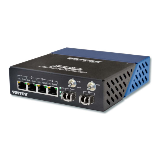
FiberPlex FP1004E User Manual 1 • General information FiberPlex 1004E Overview Elegantly simple yet packed with an advanced feature set, the FiberPlex Technologies FP1004E is a powerful 6 Port 10/100/1000 Light Industrial Ethernet Switch (see figure 1). The unit interfaces UTP RJ-45 jacks (x4) to variously populated SFP positions. -
Page 14: Features
FiberPlex FP1004E User Manual 1 • General information Figure 3. 1U TDR-01 rack shelf with FP1004E units installed Features The FiberPlex 1004E offers the following features: • Supports optional light path failure monitoring function, report switch network management • Supports hot swapping of SFP modules •... -
Page 15: Remote Network Application
FiberPlex FP1004E User Manual 1 • General information Remote Network application • IP network • VoIP • SCADA sensors • Networked audio • IP video Figure 4. Remote Network application Distributed Wi-Fi application Figure 5. Distributed Wi-Fi application Distributed IP video application Figure 6. -
Page 16: Secure Conference Room Application
FiberPlex FP1004E User Manual 1 • General information Secure Conference Room application Figure 7. Secure Conference Room application FiberPlex 1004E Front FiberPlex 1004E front panel ports, LEDs, and switches (see figure 8) are described in table 1 on page 17. -
Page 17: Front Panel Ports, Leds, And Switches
This LED indicates status of SFP slot 6 as follows: • ON—Fiber link is OK • OFF—Fiber link has failed • Blinking—Activity FX5 LED This LED indicates status of SFP slot 5 as follows: • ON—Fiber link is OK • OFF—Fiber link has failed • Blinking—Activity FiberPlex 1004E Front... -
Page 18: Fiberplex 1004E Rear
FiberPlex FP1004E User Manual 1 • General information FiberPlex 1004E Rear FiberPlex 1004E rear panel ports (see figure 9) are described in table Figure 9. FP1004E rear panel ports Table 2. Rear panel ports Item Description Circular DC Power DC power entry for the unit. This is a standard DC connection for use Connection with the included DC wall power supply. -
Page 19: Installation
Chapter 2 Installation Chapter contents Introduction ................................20 Initial Inspection ..............................20 Unpacking................................20 Disposal of Packing Materials .........................20 Choosing the Installation Site..........................20 Ambient Temperature .............................20 Grounding and Power Supply .........................21 Power Requirements and Mounting ........................21 Redundant Power ............................21 Standalone ..............................21 Surface Mount ..............................21 DIN Rail ................................22... -
Page 20: Introduction
FiberPlex FP1004E User Manual 2 • Installation Introduction This chapter describes installing the following FP1004E. Installation consists of the following: • Inspecting the FP1004E shipping container (see section “Initial Inspection”) • Unpacking the FP1004E (see section “Initial Inspection”) • Selecting an appropriate installation site (see section “Choosing the Installation Site”) •... -
Page 21: Grounding And Power Supply
FiberPlex FP1004E User Manual 2 • Installation • The permissible ambient temperature range for operation of the semiconductor components is 13 to 158°F (-10 to 40°C) (commercial temperature range for operation). • The air flow through the installation must allow exhaust air to remain cooler than 70 °C at all times. •... -
Page 22: Din Rail
FiberPlex FP1004E User Manual 2 • Installation Figure 10. FP1004E Surface Mount DIN Rail Using the TD-DINR, the FP1004E can be mounted to a DIN rail. See the TD-DINR user manual for more details on configuration options. Mount the FP1004E the TD-DINR in the same manner regardless of the ini- tial configuration of the mount itself or the height of top hat DIN rail utilized (35 x 7.5 or 35 x 15mm). -
Page 23: Tray Mounting
FiberPlex FP1004E User Manual 2 • Installation Figure 11. FP1004E installation on a TD-DINR Tray Mounting Complementing the flexibility of the FiberPlex TD Series of fiber optic modules, the TDR-01-AC provides mounting, power and cable management for up to 3 FP1004E modules in a compact and rugged aluminum 1U rack (see figure 12 on page 24). -
Page 24: Inserting And Removing Sfp Modules
FiberPlex FP1004E User Manual 2 • Installation Figure 12. FP1004E installation on a TDR-01-AC tray Inserting and Removing SFP Modules SFP Modules are static sensitive. To prevent damage from electrostatic discharge (ESD), it is recommended to attach an ESD preventative wrist strap to your wrist and to a bare metal surface when you install or remove an SFP Module. -
Page 25: Identifying The Latch Type Of The Sfp Module
FiberPlex FP1004E User Manual 2 • Installation Identifying the Latch Type of the SFP Module SFP module have various latching mechanisms to secure them into the SFP Cage of a device. FiberPlex Mod- ules can support a host of manufacturers and brands of SFP Modules so the user may encounter any number of different latches. -
Page 26: Removing A Module
FiberPlex FP1004E User Manual 2 • Installation .Removing a Module 1. Attach an anti-static wrist or ankle strap, following its instructions for use. 2. Disconnect and remove all interface cables from SFP module. 3. Release the latching mechanism (see figure 14). -
Page 27: Additional Information
FiberPlex FP1004E User Manual 2 • Installation Figure 16. Removing a module Congratulations! You have installed the FP1004E. Refer to section “Additional Information” if you want to bond the FP1004E to another FP1004E, or for information regarding SFP MSA compliance. Additional Information Bonding Units Two FP1004E can be bonded together locally to make the equivalent of an 8 Copper x 2 fiber switch by using... -
Page 28: Pinout Comparison Chart
FiberPlex FP1004E User Manual 2 • Installation standard for the form and function of SFP modules. However, not all SFPs produced are MSA compliant. The MSA provides for a transceiver (TX/RX) pinout. Other industries such as broadcast had the need for dual TX and dual RX SFP for uni-directional applications such as video. -
Page 29: Contacting Patton For Assistance
Chapter 3 Contacting Patton for Assistance Chapter contents Introduction ................................30 Contact information..............................30 Online Support ...............................30 Contacting Patton Technical Services for Free Support ...................30 Warranty Service and Returned Merchandise Authorizations (RMAs)..............30 Warranty coverage ............................31 Out-of-warranty service ..........................31 Returns for credit ............................31 Return for credit policy ..........................31... -
Page 30: Introduction
Contact information Patton Electronics offers a wide array of free technical services. If you have questions about any of our other products we recommend you begin your search for answers by using our technical knowledge base. Here, we have gathered together many of the more commonly asked questions and compiled them into a searchable... -
Page 31: Warranty Coverage
RMA#: xxxx 7622 Rickenbacker Dr. Gaithersburg, MD 20879-4773 USA Patton will ship the equipment back to you in the same manner you ship it to us. Patton will pay the return shipping costs. Warranty Service and Returned Merchandise Authorizations (RMAs) -
Page 32: Disposal Of Used Equipment
FiberPlex FP1004E User Manual 3 • Contacting Patton for Assistance Disposal of Used Equipment Used equipment contains valuable raw materials as well as substances that must be disposed of professionally. Please dispose of used equipment via an authorized specialist dealer or via the public waste disposal system, ensuring any material that can be recycled has been. -
Page 33: A Compliance Information
Appendix A Compliance Information Chapter contents Regulatory Information ............................34 EMC Directive: ..............................34 Low-Voltage Directive (Safety): ........................34 PSTN: ................................34 Radio and TV Interference (FCC Part 15) ......................34 CE Declaration of Conformity ..........................34 Authorized European Representative ........................35 Service ...................................35... -
Page 34: Regulatory Information
RoHS compliance and Council Directive 2009/125/EC establishing a frame- work for the setting of ecodesign requirements for energy-related products. The Declaration of Conformity may be obtained from Patton Electronics, Inc at www.patton.com/certifications. The safety advice in the documentation accompanying this device shall be obeyed. The conformity to the above directive is indicated by CE mark on the device. -
Page 35: Authorized European Representative
Oxford, OX1 1BE, UK Service All warranty and non-warranty repairs must be returned freight prepaid and insured to Patton Electronics. All returns must have a Return Materials Authorization number on the outside of the shipping container. This number may be obtained from Patton Electronics Technical Services at: •... -
Page 36: Specifications
Appendix B Specifications Chapter contents Supported Standards .............................37 Electrical Specifications ............................37 Optical Specifications ............................38 Physical Specifications ............................38... -
Page 37: Supported Standards
FiberPlex FP1004E User Manual B • Specifications Supported Standards Table 4. Copper UTP RJ-45 Interface IEEE Standard Cable Data Rate IEEE Max Distance 10BASE-T CAT-3 or better 10 Mbps 100 m 100BASE-T CAT-5 or better 100 Mbps 100 m 1000BASE-T CAT-5e or better 1000 Mbps 100 m... -
Page 38: Optical Specifications
FiberPlex FP1004E User Manual B • Specifications Optical Specifications External SFP Interface Max Unit ‐ ‐ Data Rate Storage Temperature (°C) 1.25 Gbps Recommended Jitter Operating Temperature (°C) ‐ ‐ Psec Operating Voltage Voltage Range ‐ ‐ Maximum Current Supply Current with SFP ports empty ‐... - Page 39 FiberPlex FP1004E User Manual B • Specifications Physical Specifications...
Need help?
Do you have a question about the FiberPlex 1004E and is the answer not in the manual?
Questions and answers