Table of Contents
Advertisement
Quick Links
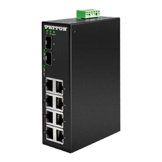
FiberPlex™ Model 1008E
10-Port Industrial Unmanaged
Ethernet Switches (8*10/100/
1000Tx + 2*100/1000 SFP Slot)
User Manual
This is a Class A product. In a domestic environment this product may cause radio interference in
which case the user may be required to take adequate measures.
Sales Office:
+1 (301) 975-1000
Technical Support:
+1 (301) 975-1007
E-mail:
support@patton.com
WWW:
www.patton.com
Part Number: 50000052, Rev. A
Revised: February 26, 2020
Advertisement
Table of Contents

Related Manuals for Patton FiberPlex 1008E


Summary of Contents for Patton FiberPlex 1008E
- Page 1 This is a Class A product. In a domestic environment this product may cause radio interference in which case the user may be required to take adequate measures. Sales Office: +1 (301) 975-1000 Technical Support: +1 (301) 975-1007 E-mail: support@patton.com WWW: www.patton.com Part Number: 50000052, Rev. A Revised: February 26, 2020...
- Page 2 Under no condition shall Patton Electronics be liable for any damages incurred by the use of this product. These damages include, but are not limited to, the following: lost profits, lost savings and incidental or consequential damages arising from the use of or inability to use this product.
-
Page 3: Summary Table Of Contents
........................32 Contacting Patton for Compliance Information . -
Page 4: Table Of Contents
........................32 Contacting Patton for Introduction ................................33... - Page 5 FiberPlex 1008E User Manual PSTN: ................................36 Radio and TV Interference (FCC Part 15) ......................36 CE Declaration of Conformity ..........................36 Authorized European Representative ........................37 Service ...................................37 Specifications ..............................38 Standard ................................39...
-
Page 6: List Of Figures
List of Figures FP1008E front panel ..............14 Straight-through cable schematic . -
Page 7: List Of Tables
List of Tables LED Indicators for FP1008E ............. . 14 RJ-45 pin assignments . -
Page 8: About This Guide
Chapter 6 on page 30 describes steps for troubleshooting problems that may arise with the FP1008E Chapter 7 on page 32 explains how to contact Patton for support • Appendix A on page 35 provides compliance information for the FP1008E •... -
Page 9: Safety When Working With Electricity
FiberPlex 1008E User Manual About This Guide The alert symbol and CAUTION heading indicate a potential hazard. Strictly follow the instructions to avoid property damage. CAUTION The shock hazard symbol and CAUTION heading indicate a potential electric shock hazard. Strictly follow the instructions to avoid property damage caused by electric shock. - Page 10 FiberPlex 1008E User Manual About This Guide In accordance with the requirements of council directive 2002/ 96/EC on Waste of Electrical and Electronic Equipment (WEEE), ensure that at end-of-life you separate this product from other waste and scrap and deliver to the WEEE collection system in your country for recycling.
-
Page 11: General Information
Chapter 1 General information Chapter contents Overview ................................12 Features .................................12 Package Contents ..............................12... -
Page 12: Overview
1 • General information Overview Patton’s FP1008E industrial gigabit unmanaged Ethernet switch are IP30 rated and DIN-Rail mountable. Each unit is designed with 8 gigabit Ethernet ports and 2 dual rate (100/1000) SFP slots, making it ideal for applications that demand high bandwidth and long distance communication. -
Page 13: Hardware Description
Chapter 2 Hardware Description Chapter contents Front panel................................14 Indicators..............................14 Ethernet Ports ..............................15 Cabling..................................17 Wiring the Power Inputs ............................19 Wiring the Fault Alarm Contact..........................20... -
Page 14: Front Panel
FiberPlex 1008E User Manual 2 • Hardware Description Front panel The front panel of the FP1008E industrial gigabit unmanaged Ethernet switch is shown in figure Figure 1. FP1008E front panel LED Indicators There are LED light indicators located on the front panel of the industrial Ethernet switch that display the power status and network status. -
Page 15: Ethernet Ports
FiberPlex 1008E User Manual 2 • Hardware Description Table 1. LED Indicators for FP1008E (Continued) Color Description Connected to network LNK/ACT Green Flashing Networking is active (SFP Port) Not connected to network Green Connected to network, 1000 Mbps Flashing Networking is active LAN Port 1–5... -
Page 16: Straight-Through Cable Schematic
FiberPlex 1008E User Manual 2 • Hardware Description Figure 2 figure 3show the cabling schematics for straight-through and crossover Figure 2. Straight-through cable schematic Figure 3. Crossover cable schematic Figure 4, along with figure 5 figure 6 on page 17 show the 10, 100, and 1000 Ethernet RJ-45 pinouts. -
Page 17: Cabling
FiberPlex 1008E User Manual 2 • Hardware Description Figure 5. Straight-through cable schematic Figure 6. Crossover cable schematic Cabling Use the four twisted-pair, category 5e, or the above cabling for RJ-45 port connections. The cable between the switch and the link partner (switch, hub, workstation, etc.) must be less than 100 meters (328 ft.) long. -
Page 18: Transceiver To The Sfp Module
FiberPlex 1008E User Manual 2 • Hardware Description Figure 7. Transceiver to the SFP Module Figure 8. Transceiver Inserted 2. Insert the fiber cable of the LC connector into the transceiver as shown in figure Figure 9. LC Connector to the Transceiver To remove the LC connector from the transceiver, do the following: 1. -
Page 19: Wiring The Power Inputs
FiberPlex 1008E User Manual 2 • Hardware Description Figure 10. Remove LC Connector 2. Push down the metal clasp and pull the transceiver out by the plastic part as shown in figure Figure 11. Pull Out from the SFP Module... -
Page 20: Wiring The Fault Alarm Contact
FiberPlex 1008E User Manual 2 • Hardware Description Figure 13. Power Terminal Block 2. Tighten the wire-clamp screws to prevent the wires from loosening, as shown in figure Figure 14. Power Terminal Block Only use copper conductors, 60/75°C, tightened to 5 lbs. - Page 21 FiberPlex 1008E User Manual 2 • Hardware Description The wire gauge for the terminal block should range between 12 ~ 24 AWG. If only using one power source, jumper Pin 1 to Pin 5 and IMPORTANT Pin 2 to Pin 6 to eliminate power fault alarm.
-
Page 22: Mounting Installation
Chapter 3 Mounting Installation Chapter contents DIN-Rail Mounting ..............................23 Wall Mounting..............................24... -
Page 23: Din-Rail Mounting
FiberPlex 1008E User Manual 3 • Mounting Installation DIN-Rail Mounting The DIN-Rail is pre-installed on the industrial Ethernet switch from the factory. If the DIN-Rail is not on the industrial Ethernet switch, see figure 16 to learn how to install the DIN-Rail on the switch. -
Page 24: Wall Mounting
FiberPlex 1008E User Manual 3 • Mounting Installation Figure 17. Insert the Switch on the DIN-Rail 4. Lightly pull down the bracket on to the rail as shown in figure Figure 18. Stable the Switch on DIN-Rail 5. Check if the bracket is mounted tightly on the rail. -
Page 25: Remove Din-Rail Bracket From The Switch
FiberPlex 1008E User Manual 3 • Mounting Installation 4. Use the hook holes at the corners of the wall mounting bracket to hang the industrial Ethernet switch on the wall. 5. To remove the wall mount bracket, do the opposite from the steps above. -
Page 26: Hardware Installation
Chapter 4 Hardware Installation Chapter contents Installation Steps ..............................27... -
Page 27: Installation Steps
FiberPlex 1008E User Manual 4 • Hardware Installation Installation Steps This section will explain how to install Patton's FP1008E: 10-port industrial gigabit unmanaged Ethernet switch with 8*10/100/1000Tx + 2*100/1000 SFP slots. 1. Unpack the industrial Ethernet switch from the original packing box. -
Page 28: Network Application
Chapter 5 Network Application Chapter contents Introduction ................................29... -
Page 29: Introduction
FiberPlex 1008E User Manual 5 • Network Application Introduction Figure 21 shows an example of an industrial Ethernet switch application. Figure 21. Industrial Ethernet Switch Application Reference Introduction... -
Page 30: Troubleshooting
Chapter 6 Troubleshooting Chapter contents Procedure ................................31... -
Page 31: Procedure
If the power indicator LED does not turn on when the power cord is plugged in, the user may have a problem with the power cord. Check for loose power connections, power losses or surges at the power outlet. Please contact Patton for technical support service, if the problem still cannot be resolved. •... -
Page 32: Contacting Patton For
Chapter 7 Contacting Patton for assistance Chapter contents Introduction ................................33 Contact information..............................33 Warranty Service and Returned Merchandise Authorizations (RMAs)..............33 Warranty Coverage ............................33 Out-of-Warranty Service ..........................33 Returns for Credit ............................33 Return-for-Credit Policy ...........................34 RMA Numbers ...............................34 Shipping Instructions ............................34... -
Page 33: Introduction
If you have ordered the wrong equipment or you are dissatisfied in any way, please contact us to request an RMA number to accept your return. Patton is not responsible for equipment returned without a Return Authorization. -
Page 34: Rma Numbers
RMA#: xxxx 7622 Rickenbacker Dr. Gaithersburg, MD 20879-4773 USA Patton will ship the equipment back to you in the same manner you ship it to us. Patton will pay the return shipping costs. Warranty Service and Returned Merchandise Authorizations (RMAs) -
Page 35: Compliance Information
Appendix A Compliance Information Chapter contents Regulatory Information ............................36 EMC Directive: ..............................36 PSTN: ................................36 Radio and TV Interference (FCC Part 15) ......................36 CE Declaration of Conformity ..........................36 Authorized European Representative ........................37 Service ...................................37... -
Page 36: Regulatory Information
The Declaration of Confor- mity may be obtained from Patton Electronics, Inc at www.patton.com/certifications. The safety advice in the documentation accompanying this device shall be obeyed. The conformity to the above directive is indicated by CE mark on the device. -
Page 37: Authorized European Representative
Oxford, OX1 1BE, UK Service All warranty and non-warranty repairs must be returned freight prepaid and insured to Patton Electronics. All returns must have a Return Materials Authorization number on the outside of the shipping container. This number may be obtained from Patton Electronics Technical Services at: •... -
Page 38: Specifications
Appendix B Specifications Chapter contents Standard ................................39 EMI..................................39 Stability Testing ..............................39 Safety..................................39 Protocol.................................39 Transmission Line ..............................39 Transmission Distance ............................39 Transmission Speed...............................39 Address................................39 RJ45 (Ethernet) Port .............................40 SFP Slot ................................40 ..................................40 Network Cable ..............................40 Over Current Protection ............................40 Power Input ................................40 Fault Output .................................40 Max Power... -
Page 39: Standard
FiberPlex 1008E User Manual B • Specifications Standard • IEEE 802.3 10BaseT Ethernet IEEE 802.3u 100BaseTX Fast Ethernet • IEEE 802.3ab 1000BaseT • • IEEE 802.3z gigabit Fiber • FCC Class A CE EN61000-4-2,3,4,5,6,8,11,12 • CE EN61000-6-2 • CE EN61000-6-4 •... -
Page 40: Rj45 (Ethernet) Port
FiberPlex 1008E User Manual B • Specifications RJ45 (Ethernet) Port Up to 1000Mbps SFP Slot 2*SFP slots support dual rate 100/1000 • Power Unit: P1 (Green), P2 (Green), Fault (Red) Ethernet port: Link/active (Green), 1000Mbps • SFP: Link/active (Green) •... -
Page 41: Physical
0.78 oz (22 g) Dimensions IP-30, 1.81W x 3.89D x 5.59H in. (46W x 99D x 142H mm) Figure 22 on page 42 shows the physical dimensions of Patton’s FP1008E: 10-port industrial gigabit unman- aged Ethernet switch with 8*10/100/1000Tx + 2*100/1000SFP slots. Physical... -
Page 42: Fp1008E Physical Dimensions
FiberPlex 1008E User Manual B • Specifications Figure 22. FP1008E Physical Dimensions Physical... -
Page 43: Accessories
Appendix C Accessories Chapter contents Optional Accessories..............................44... -
Page 44: Optional Accessories
FiberPlex 1008E User Manual C • Accessories Optional Accessories Patton Model # Description PS-03671H1-002 AC/DC 12V, 2A Power Adapter (0 to 50°C) PS-03671H1-020 AC/DC 21–27V, 15W Power Adapter (-40 to 85°C) NS-1001R-19ADJDIN 19” Rackmount Adjustable Depth 35mm DIN Rail Kit...
Need help?
Do you have a question about the FiberPlex 1008E and is the answer not in the manual?
Questions and answers