Table of Contents
Advertisement
Advertisement
Table of Contents

Subscribe to Our Youtube Channel
Related Manuals for Rinnai BRIVIS Touch


Summary of Contents for Rinnai BRIVIS Touch
- Page 1 Models: Rinnai Touch Controller Installation Manual...
- Page 2 • The Touch Controller is compatible with selected units only. For information on compatibility please contact your Dealer. Interface Module • Your Touch Controller is compatible with the Rinnai Touch App, Power Transformer however they are independent items. An additional Wi-Fi accessory Power &...
-
Page 3: Table Of Contents
Table of Contents 3.12 Outdoor Temperature Sensor (Optional) ..... 16 4.0 Calibrating the Touch Controller ......17 1.0 Home Screen – Key Functions ........ 5 5.0 Product and Warranty Registration ......18 2.0 Touch Controller Installation ........6 6.0 Instruct Home Owner on System Operation ..18 2.1 Location of the Touch Controller ...... - Page 4 Definitions Zone Networker One room or a group of rooms; normally selected on the basis of Networker is a term used for a temperature sensing or usage or that have similar heating or cooling needs. communicating device which communicates over two-wire bus. There can be only one Master Networker (n01), all others must be Controlled Zone slaves (n02, n03, n10).
-
Page 5: Home Screen - Key Functions
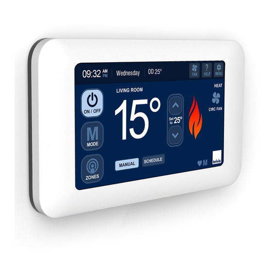
1.0 Home Screen – Key Functions Fan Select Mode Adjust Set Digital Temperature Clock Menu – Display Diagram 1: Heating Home Screen Options or Settings Mode Indicator Power Fan Status Indoor Indicator Temperature Flame System Mode Symbol (HEAT/COOL/EVAP) Zones Where Fitted * * Active with MTSP &... -
Page 6: Touch Controller Installation
2.0 Touch Controller Installation To connect the appliance to the Touch Controller: 1. Determine location of the Touch Controller. The Touch Controller is connected to a compatible appliance 2. Determine location of the Interface Module. through the Interface Module. A 20m, four core, Power & 3. -
Page 7: Location Of The Interface Module
2.2 Location of the Interface Module To mount the Touch Controller: The Interface Module shall be located within 1.5m of a 10 Amp 1. Run the supplied P&C Loom from the Touch Controller 240 volt fixed switched socket outlet. The Touch Controller shall to the Interface Module. -
Page 8: Install Interface Module
2.5 Install Interface Module Diagram 7: Mounting Touch Controller to Backing Plate The Interface Module facilitates communication between the Male Clips Touch Controller and the appliance(s) through the P&C Loom, and is capable of connecting up to four Touch Controller units. The Interface Module requires a 12VDC power supply from the Power Transformer. -
Page 9: Connection Of Interface Module To P&C Loom
To install the Interface Module: 2.6 Connection of Interface Module to P&C Loom 1. Position in an environmentally protected area where the The Interface Module is capable of connecting up to four temperature does not exceed 70°C. Touch Controllers. The P&C Loom can be connected to the 2. -
Page 10: Connection Of Interface Module To Appliance
2.7 Connection of Interface Module to Appliance For more information regarding appliance connection please refer to the product installation manual supplied with the The Interface Module has four terminal points for the appliance. connection of the Appliance control wires TW1 & TW2. When connecting to an appliance, use only the first set Note: When there is more than one appliance connected to the (Set 1) of two terminals or the second set (Set 2). -
Page 11: Set Day/Time
3.2 Set Day/Time 3. The MENU > SET DAY/TIME screen will appear, refer Diagram 14. To modify either the day or the time press the buttons To access and modify the day and time do the following: adjacent to the time and day. 1. -
Page 12: Installer Setup
Note: If multiple Touch Controllers are installed, only the Master When accessing the CUSTOM SETUP screen through the Master Controller has the ability to set the day and time. The Master Touch Controller the following options may be available, and is Controller can be identified by the letter "M"... -
Page 13: Reset Networker Id
When accessing the CUSTOM SETUP screen through a Slave Touch Controller the following option will be available. Diagram 18: Confirmation to prompt ID change 1. Reset the identification of the Touch Controller, refer Diagram Diagram 17: Slave Touch Controller INSTALLER SETUP Diagram 19: Set Networker Address 3.4 Reset Networker ID On either the Master Touch Controller or Slave Touch... -
Page 14: Networker Parameters
3.5 Networker Parameters Accessing ‘n02 to n09 – Slave Controllers’ The ‘NETWORKER PARAMETERS’ section in the Master Touch Controller provides access to all Networkers connected to the Press the ‘n02 – Slave Networker’ button through to ‘n09 – Slave system. This may range from n01 through to n10 if installed, refer Networker’... -
Page 15: System With Zones (Inc. Zoneplus)
- One Gas Ducted Heater 3.11 Service Notification Message - One Gas Ducted Heater + one Evaporative Cooler When the operating hours logged for an appliance exceeds the - One Gas Ducted Heater + one Add-On predetermined period, the Touch Controller displays the following: Note: For Refrigerated Cooling connection, heater parameters Diagram 21: System Alert (H01) must be programmed. -
Page 16: Outdoor Temperature Sensor (Optional)
Diagram 22: Fan run hour limit Diagram 23: NT-1 The owner can book a service call or clear the spanner icon notification by pressing the “Clear” button 3.12 Outdoor Temperature Sensor (Optional) The Touch Controller can display the ambient (outdoor) temperature. -
Page 17: Calibrating The Touch Controller
4.0 Calibrating the Touch Controller Diagram 25: Touch Controller Screen Calibration The Touch Controller leaves the factory with the touch screen calibrated ready for use. Should the touch screen require calibration this can be achieved by doing the following: 1.Turn the system off if running 2.Remove the Touch Controller from the backing plate leaving the loom connected 3.Locate dip switches at the rear of the Touch Controller as... -
Page 18: Product And Warranty Registration
• owner that product registration can be completed either: Touch Controller will resume normal operation with the mode on-line at rinnai.com.au and settings immediately before the outage. • or via the registration form in the product Owner’s Manual (e.g. When powered OFF, the controller will retain its Day and Time •... -
Page 19: Appendix
7.0 Appendix Table 2: Master Controller Parameters Parameter ID Installer Parameter Description Installer Parameter Please record Number the values you Value Settings Value have set (default) n01 ID00:0 Networker Address or Number Master = 1; Slave ≥ 2 n01 ID01:1 Refrig Common Zone - Enable Refrig/Heater ID No. - Page 20 Parameter ID Please record Installer Parameter Number and Installer Parameter Description the values you Value Settings Value have set (default) n01 ID23:0 Heating Zone C - Unit Heater ID No. n01 ID24:3 Heating Zone C - Relay Relay No. 1 to 4 n01 ID25:1 Heating Zone C - Temperature Sensing ID No.
- Page 21 Notes:...
- Page 22 Notes:...
- Page 23 Notes:...
- Page 24 Tel: 1300 555 545* Fax: 1300 555 655 Monday to Friday, 8.00 am to 5.00 pm EST. *Cost of a local call higher from mobile or public phones. For further information visit www.rinnai.com.au or email enquiry@rinnai.com.au innai has a Service and Spare Parts network with personnel who are fully trained and equipped to give the best service on your innai appliance.
Need help?
Do you have a question about the BRIVIS Touch and is the answer not in the manual?
Questions and answers