
Related Manuals for Systema OHA 100


Summary of Contents for Systema OHA 100
- Page 1 RADIANT BANDS OHA 100 - OHA 200 - OHA 400 INSTRUCTION MANUAL GREAT BRITAIN "INSTALLATION, USE AND MAINTENANCE" Cod. 10CNDE0001...
- Page 2 SYSTEMA S.p.A. IMPORTANT: Please read this manual carefully before turning the radiant band on. With the aim of constantly improving its products, Systema reserves the right to change the contents without prior notice. Via San Martino 17/23 E-mail: systema@systema.it S. GIUSTINA IN COLLE (PD) loc.
-
Page 3: Table Of Contents
DIMENSIONS OF THE RADIANT BAND ....... . .15 OHA 100, OHA 200, OHA 400 COMBUSTION HEAD ..... . .16 3.6.1... - Page 4 SYSTEMA S.p.A. 4.10 INSTALLING THE RADIANT BAND WITH THE ADDITIONAL REFLECTING SIDE 54 GAS PIPING ..........55 ELECTRIC WIRING .
-
Page 5: General Standards
Before using the appliance, read this manual carefully. The instructions given herein must be scrupulously followed, especially with regards the safety standards. Systema declines all responsibility for direct or indirect damage caused to people, animals and property by failure to observe the instructions given herein. -
Page 6: Technical Feature
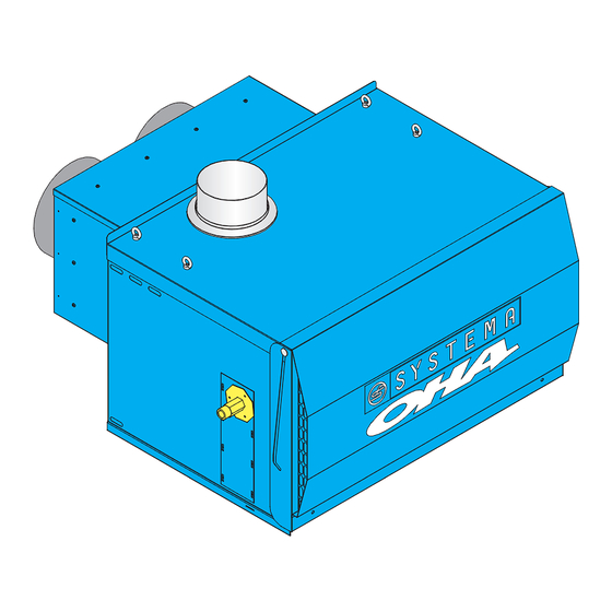
SYSTEMA S.p.A. TECHNICAL FEATURE OPERATING DESCRIPTION AND FEATURES OHA radiant bands are composed of a suspended combustion chamber on the outside and a radiant band installed inside the room to be heated. The combustion chamber generates heat through a gas burner, and the vector fluid is constantly recycled by a fan inside the airtight radiant band which is depressed with respect to the heated area. -
Page 7: Technical Features Of The Combustion Unit
3.2.1 Code table Model, unit and thermal capacity Type of fuel Version Air lock type Combustion chamber type OH10050 Oha 100-50 kW Standard combustion chamber OH10100 Oha 100-100 kW Combustion chamber with 45° curve OH20115 Combustion chamber with 90° curve... - Page 8 SYSTEMA S.p.A. OHA 100 OHA 200 MODEL VERSION OHA100-50 OHA100-100 OHA200-115 OHA200-150 OHA200-180 Thermal capacity kW (Hi) 45,5 93,0 105,2 138,0 165,6 Thermal power kW (Hi) 91,0 93,0 91,5 92,0 92,0% Combustion efficiency average Rated CONSUMPTION 5,29 10,58 12,17 15,87...
- Page 9 SYSTEMA S.p.A. Band model M Band model U Band model U Band model U 1 tube Ø 300 mm 2 tube Ø 200 mm 2 tube Ø 300 mm 2 tube Ø 400 mm Thermal capacity [kW] Min. Max. Min.
-
Page 10: Features Of The Generator Components
SYSTEMA S.p.A. 3.2.2 Main components in the generator Description Codice Control equipment 00CEAP0776 00CEPR1110 Adjustable air pressure switch 50÷500 Pa 05ASMO0100 Motor 1,1 kW 1.400 rpm + fan wheel Ø 330 x H 140 05ASMO0101 Motor 3 kW 2.820 rpm + fan wheel Ø 330 x H 100 Motor 4 kW 2.880 rpm + fan wheel Ø... - Page 11 SYSTEMA S.p.A. ASYNCHRONOUS THREE-PHASE ELECTRIC MOTOR 3 kW Code ...........05CEMO0763 Electric power supply .
-
Page 12: Explosion Of The Thermal Unit
SYSTEMA S.p.A. EXPLOSION OF THE THERMAL UNIT Rev. 16GB1304... - Page 13 SYSTEMA S.p.A. Pos. Description Q.ty Plenum Female-M8 eyebolt Bottom collar Top collar Top outside panel Machine body Sealing frame Right side external panel Sheath clamp Ø 35 mm Sheath clamp Ø 35 mm (nut) Combustion chamber Motor complete with impeller and flange...
-
Page 14: Dimensions Of The Generator
SYSTEMA S.p.A. DIMENSIONS OF THE GENERATOR FRONT VIEW SIDE VIEW E l e c t r i c i t y Gas supply supply SIDE VIEW Fig.3.2 External dimensions of the OHA heating unit Dimension [mm] Dimension [mm] Height Height... -
Page 15: Dimensions Of The Radiant Band
SYSTEMA S.p.A. DIMENSIONS OF THE RADIANT BAND Dimensions Level 1 pıpe 2 pıpe 2 pıpe Ø300 Ø300 Ø400 1020 1088 Weight (kg/m) Weight (kg/m) upper plate Weight (kg/m) protectıon grıd Tab.3.7 Fig.3.3 Overall dimensions of the band Example: weight of mod. U 300 radiant strip with upper plate and lower protection net Total weight for meter = 28 + 4,0 + 2,0 = 34,0 kg/m Rev. -
Page 16: Oha 100, Oha 200, Oha 400 Combustion Head
SYSTEMA S.p.A. OHA 100, OHA 200, OHA 400 COMBUSTION HEAD OHA 100 U.M. Natural gas G20 LPG G30/G31 Thermal capacity Cone diameter Combustion chamber diameter Combustion chamber extended diameter Combustion head code 05CNTO2506 Number of additional injectors Without injectors Combustion chamber depression... - Page 17 SYSTEMA S.p.A. OHA 200 U.M. Metano G20 GPL G30/G31 Thermal capacity Cone diameter Combustion chamber diameter Combustion chamber extended diameter Combustion head code 05CNTO2505 05CNTO2506 Number of additional injectors Without injectors Combustion chamber depression mbar Gas diaphragm diameter Pressure at the nozzle...
- Page 18 SYSTEMA S.p.A. OHA 400 U.M. Metano G20 GPL G31 Thermal capacity Cone diameter Combustion chamber diameter Combustion chamber extended diameter Combustion head code 05CNTO2505 Number of additional injectors Combustion chamber depression mbar Gas diaphragm diameter Pressure at the nozzle mbar...
-
Page 19: Diaphragm And Electrode Positions
SYSTEMA S.p.A. 3.6.1 Diaphragm and electrode positions DIAPHRAGM Fig. 3.4 Diaphragm position Fig. 3.5 Combustion head with electrode positions Rev. 16GB1304... -
Page 20: Installation
SYSTEMA S.p.A. 4 INSTALLATION INSTALLATION AREA AND SAFETY DISTANCE Roof OHA Radiant band Insulation min. 3 cm thick Protection plate (stainless steel, galvani- sed plate, aluminium) Electric motor which must give an air passage sufficient for ventilating the electric motor OVERHEAD TRAVELLING CRANE Fig.4.1 Protection for the overhead travelling crane... -
Page 21: Assembly Sequence For The Band
SYSTEMA S.p.A. ASSEMBLY SEQUENCE FOR THE BAND DRILL THE HOLES IN THE WALL (refer to para- graph 4.4.2 phases 5a/5b e 4.4.3) Fig.4.3a INSTALLING THE SUPPORTING PLATFORM (refer to paragraph 4.4.2) Fig.4.3b FITTING THE COMBUSTION CHAMBER (refer to paragraphs 4.4.3; 4.5 e 4.6.1) Fig.4.3c... - Page 22 SYSTEMA S.p.A. FITTING THE BRACKETS (refer to paragraph 4.7) Dist max. 3m Fig.4.3d INTALLING THE PIPES (refer to paragraphs 4.7.2; 4.7.3; 4.7.4; 4.7.5 e 4.7.7) Fig.4.3e FITTING THE SIDES AND TOP INSULATION (refer to paragraphs 4.7; 4.7.1; 4.7.5; 4.7.6 and 4.7.8)
-
Page 23: Modular Platform
SYSTEMA S.p.A. MODULAR PLATFORM 4.4.1 Platform composition = Optional kits Fig. 4.4 modular platform Rev. 16GB1304... -
Page 24: Rei120
SYSTEMA S.p.A. Optional Platform kit Angular glass Panel support kit Pos. Code Description cod.05ACKT0500 fixing bracket kit REI120 [Q.ty] cod. 05ACKT0502 cod. 05ACKT0501 [Q.ty] [Q.ty] 1 05CVPA8000 Panel support spacer REI120 Left hand angular support bracket 2 05CVPA8002 for glass fixing... - Page 25 SYSTEMA S.p.A. 4.4.2 Assembling the standard platform (without glass fixing bracket kit and panel support kit REI120) Phase 1 Fig.4.5 Position of the reinfor- cing plate Phase 2 N.B. Place the reinforcing plate as shown in fig. 12 Fig.4.6 Rev. 16GB1304...
- Page 26 SYSTEMA S.p.A. Phase 3 Fig.4.7 Phase 4 Fig.4.8 Rev. 16GB1304...
- Page 27 SYSTEMA S.p.A. Phase 5: Front view of the outside of the wall Drilling the wall Hole in the wall for the plenum Dimensions Dimensions for pipe Level [mm] Ø400 [mm] Tab.4.2 Hole Ø 20 mm in the wall for fixing the platform Fig.4.9...
- Page 28 SYSTEMA S.p.A. Fig.4.11 Fixing the platform with the glass fixing kit, see fig. 4.13 for the template. Version with pipe Ø 300 mm Version with pipe Ø 400 mm Panel REI 120 Panel REI 120 Fig.4.12a Front view of unit OHA with panel REI 120 dimensions Fig.4.12 Fig.17b...
-
Page 29: Hole For Platform With Glass Holder Kit And Rei120 Panel Support Kit
SYSTEMA S.p.A. 4.4.3 Hole for platform with glass holder kit and REI120 panel support kit FRONT VIEW OF THE OUTSIDE OF Hole Ø 20 mm in the wall THE WALL for fixing the platform Oha100, Dimensions Oha200 Level for pipe Oha400 Ø... -
Page 30: Tilted Bracket For Roof Unit
SYSTEMA S.p.A. TILTED BRACKET FOR ROOF UNIT Fig. 4.16 Tilted roof bracket Pos. Code Description Quantity 05CNSU0006 Right/left support 05CNAN0009 Angle iron 05CNPA0001 Graduated right/left part 05CNTR0008 Bottom crosspiece 00CNDA0154 Nut M10 00CNVI1060 Screw TE M10x30 Tab.4.4 Rev. 16GB1304... -
Page 31: Connecting The Combustion Chamber Extension
SYSTEMA S.p.A. Fig.4.17 Positioning of the thermal unit on a an adjustable ceiling platform CONNECTING THE COMBUSTION CHAMBER EXTENSION Before positioning the OHA combustion unit, connect the combustion chamber extension using the supplied screws as shown in figures 4.18a and 4.18b. -
Page 32: Connecting The Combustion Unit To The Band
DIAMETER X COMBUSTION UNIT EXTENDED COMBUSTION TOTAL LENGTH + CHAMBER UNIT EXTENDED LENGTH CHAMBER [MM] [MM] OHA 100 204 X 500 1500 OHA 200 204 X 1000 2000 OHA 400 204 X 500 2000 Tab.4.5 Fig.4.19 CONNECTING THE COMBUSTION UNIT TO THE BAND Fig.4.20... - Page 33 SYSTEMA S.p.A. To connect the combustion unit to the radiant circuit, there are 2 nip- ples, as for the pipe joins (for more information consult paragraph 4.7.2): 1) The nipples are already screwed to the combustion unit (fig. 4.19). 2) Introduce the nipples to the out-...
-
Page 34: Assembling The Bands
SYSTEMA S.p.A. ASSEMBLING THE BANDS The bands are subject to oscillation due to expansion, therefore the chains must be long enough to allow this oscillation. 1) Fit the bracket guide in the support bracket housing. 2) Fix the support bracket to the suspension chain as shown in the enclosed figure, screw in place (refer to the detailed figure 4.23). - Page 35 SYSTEMA S.p.A. Fig.4.25 Assembling the radiant pipes To fit the sides to the brackets, fit the "U" shaped support by clicking it into the slots (A), so that the slits line up (B) as shown in fig. 25. Fig.4.26 Assembling the sides...
-
Page 36: Side Connections
SYSTEMA S.p.A. 4.9.1 Side connections Join the two sides with the connections. Leave at least 80 mm between the heads of the two sides, to allow for expansion. Fix in place with self-drilling screws. ATTENTION: the two screws must be left slightly loose so that the sides can expand inwards. -
Page 37: Connections Between Pipes
7) Self-drilling screw The joint nipples are carefully developed by Systema to assure a perfect seal, in particular to high tempera- tures, which they have to bear. They are blocked to the tubes thanks to some self-tapping screws so that the system becomes a single block. - Page 38 SYSTEMA S.p.A. Fig. 4.31 Fig. 4.32 Fig.4.33 Screws layout Fig. 4.34 Fig. 4.35 Bush insert 13 Rev. 16GB1304...
-
Page 39: Mounting The Curves
The curves can be assembled following the same steps with which the joints between the tubes are assem- bled. They are developed by Systema and assure a perfect seal, in particular they are resistant to high tem- peratures, which they have to bear. They are blocked to the tubes thanks to some self-tapping screws so that the system becomes a single block. - Page 40 SYSTEMA S.p.A. Fig.4.38 Fig. 4.39 Screws layout Fig. 4.40 Bush insert 13 For OHA 300kW and 400kW units, the first bend must be positioned at least 3 meters from the burner. Rev. 16GB1304...
-
Page 41: Mounting The Expansion Joins
SYSTEMA S.p.A. 4.9.4 Mounting the expansion joins 1) Fit the nipple (1) in the outlet pipe (2) taking care that the conical part adheres well all around the pipe. Fig. 4.44 Fig. 4.41 4) Fit the nipple (4) in the outlet pipe (5) leaving 14... - Page 42 SYSTEMA S.p.A. 6) Fix the joint to both the tubes (2 and 5) with the clamps (8); 7) Foresee a limit stop chain (7) to hook amongst the clamps. Fig. 4.46 Fig. 4.47 Rev. 16GB1304...
- Page 43 SYSTEMA S.p.A. COLD PLANT PLANT OPERATING Fig.4.48 Expansion Rev. 16GB1304...
-
Page 44: 90° Side Connections
SYSTEMA S.p.A. 4.9.5 90° Side connections Fig.4.49 90° side connections To form the 90° bend, shortern the internal side of the INTERNAL sides at level L (for the values refer to the table below) CONNECTION as shown in fig. 31. -
Page 45: Assembling The End Closed Cover
SYSTEMA S.p.A. For the external sides, repeat the same operations EXTERNAL as above: fit the 90° join in the sides and fix it in CONNECTION place with the self-tapping screws. The fixing screws must be loosely tightened outsi- de the slots, to allow the sides to expand inwards. -
Page 46: Asembling The "T" Branch
SYSTEMA S.p.A. 4.9.7 Asembling the “T” branch 1) Fit the closed radius 90° bends as shown in fig.4.53 2) Block the bends as shown in fig. 4.9.3 3) Fit the sides which were previously cut according to the need (leave a space as shown in fig. 4.55), so that the symmetry between the sides' connections is respected (see fig. -
Page 47: Assembling The Top Insulation
SYSTEMA S.p.A. 4.9.8 Assembling the top insulation PLATE DIMENSIONS Join the plates together in groups of 4 units using a screw, one above the other of at least 4-5 cm. Every 4 units the plates must be one above the other for 10-15 cm near the junction. - Page 48 SYSTEMA S.p.A. Fix with self-drilling screws Fix with self-drilling screws 45° bend 90° bend Fig. 4.57a Assembling the insulating plate on the band Fig. 4.57b Assembling the insulating plate on the band bends bends Rev. 16GB1304...
- Page 49 SYSTEMA S.p.A. Fix with self-drilling screws 1500 Fig. 4.58 Assembling the insulating plate on the “T” connections in the band Fix with self-drilling screws 1500 Fig. 4.59 Assembling the insulating plate on the vertical bends in the band Rev. 16GB1304...
-
Page 50: Vertical Connections For The Radiant Band Positioned On Two Different Levels
SYSTEMA S.p.A. 4.9.9 Vertical connections for the radiant band positioned on two different levels Fit the bored cover along the profiles of the side panels and fix in place with self-drilling screws. Fit the 90° or 45° bends into the pipes and fix as shown in 4.7.3. -
Page 51: Assembling The Bottom Grid (Optional)
SYSTEMA S.p.A. 4.9.10 Assembling the bottom grid (optional) Fig.4.62 Fixing the bottom grid Fig.4.63 Connecting the bottom grid in the bends Rev. 16GB1304... -
Page 52: Assembling The Top Shell (Optional)
SYSTEMA S.p.A. 4.9.11 Assembling the top shell (optional) Fix 4 plates together one above the other of at least 4-5cm Fix to the side with self-dril- ling screws on the side The plates must be one above the other for 10-15 cm near the junction. -
Page 53: Assembling The Reflecting Sides (Optional)
SYSTEMA S.p.A. 4.9.12 Assembling the reflecting sides (optional) Fix the bracket (A) onto the band support, as shown in the figure. Fit the reflecting sides onto the brackets, introducing the "U" side support into the slit (B) in the bracket, as shown in the figure below. -
Page 54: Installing The Radiant Band With The Additional Reflecting Side
SYSTEMA S.p.A. 4.10 INSTALLING THE RADIANT BAND WITH THE ADDITIONAL REFLECTING SIDE Additional reflecting side Fig.4.66a Installation on the wall Additional reflecting side Additional reflecting side Fig.4.66b Installation on the ceiling for very high rooms Rev. 16GB1304... -
Page 55: Gas Piping
SYSTEMA S.p.A. GAS PIPING The gas supply piping must be constructed in conformity with current legislation in the country of installation. The size of the piping and any pressure reducers must guarantee the correct operations of the appliance. The materials used must conform to current legislation in the country of installation. -
Page 56: Electric Wiring
SYSTEMA S.p.A. 6 ELECTRIC WIRING The electric wiring must be done in conformity with national and local legislation in the country of installation. The electric system must be adequate to the maximum absorbed power by the radiant band, which is given on the specification plate and in this manual;... -
Page 57: Testing And Start Up
SYSTEMA S.p.A. 1) Serial linkage between OHA thermal unit and thermostat (shielded cable which guaranties a double isolation of the parts under tensive stress with minimum section 2x0,5 mm², separate from the high voltage cables; maximum length allowed for the network connection is 300 m). -
Page 58: Ignition Phases For The Combustion Unit
SYSTEMA S.p.A. 7.1.1 Ignition phases for the combustion unit 1) When power consent is received from the gas pressure switch, the thermostat and weekly clock, the appliance is powered and begins the ignition procedure. 2) The appliance begins the pre-washing procedure for the combustion chamber and checks the air pressu- re switch works, by turning the on-board fan on and opening the air damper to maximum. -
Page 59: Air Damper Regulation
SYSTEMA S.p.A. AIR DAMPER REGULATION There are two versions of the air lock adjustment: 1) Air lock with automatic servocontrol 2) Air lock without automatic servocontrol Attention: The depressure measured in the pressure-switch must be of 40 mmCa (COOL) 1= 2... -
Page 60: Setting The Air-Differential Pressure Switch
COMBUSTION NOZZLE FUEL VERSION PRESSURE HEAD CODE PRESSURE DIAPHRAGM Natural gas G20 20 mbar 05CNTO2506 OHA 100-50 LPG propane G31 37 mbar 05CNTO2506 Natural gas G20 20 mbar 05CNTO2506 OHA 100-100 LPG propane G31 37 mbar 05CNTO2506 Natural gas G20... -
Page 61: Maintenance
Pressure test point upstream from the solenoid Pressure test point downstream from the solenoid Slow ignition regulation (set during tests performed by Systema) 1st stage flame regulation 2nd stage flame regulation Gas pressure switch N.B. Put the seal cap on the solenoid regulation device after setting. -
Page 62: Transformation From Lpg Gas To Natural Gas For Oha 300
SYSTEMA S.p.A. 4) Mount the air lock and electric plug, fixing it in place with the two screws (if an automatic air lock is used). 5) Turn the appliance on and check that the pressure to the burner is 37 mbar (pressure test point near the solenoid entrance). - Page 63 SYSTEMA S.p.A. 3-part join Fig.8.2 Dismantling the combustion head Rev. 16GB1304...
-
Page 64: Operating Faults
SYSTEMA S.p.A. OPERATING FAULTS Ground control DIAGRAM 1 panel switched on Check the electrical supply Does the ground control panel signal an error? Is the motor switched on? Does the air lock continue Check the timer laying opening and closing? (in the... - Page 65 SYSTEMA S.p.A. From DIAGRAM 2 the first diagram Is the flame first step switch Does it happen Are the pilots lights (first and the flame ionization? second step) switched on? Check the shield connector electrovalve Replace the PT100 Check the bobbins...
-
Page 66: Guarantee
9 GUARANTEE GUARANTEE COVER AND VALIDITY 1) The guarantee only covers faults in the materials or construction of components supplied by SYSTEMA. In this case, SYSTEM will repair or replace ex works the faulty parts free of charge, IT BEING UNDER- STOOD THAT ANY OTHER FORM OF GUARANTEE OR DAMAGE IS EXPRESSLY EXCLUDED. -
Page 67: Guarantee Effectivenes And Enforcement
SYSTEMA S.p.A. Certificate to the Service Centre. 2) The Service Centre will send a technician during normal working hours, their own commitments permitting. GUARANTEE EFFECTIVENES AND ENFORCEMENT 1) For the guarantee to become effective, the customer must: a) Ask the installer for the name of the Service Centre for the first "Start-up". -
Page 68: Ce Certificate
SYSTEMA S.p.A. 11 CE CERTIFICATE Rev. 16GB1304... - Page 69 SYSTEMA S.p.A. Rev. 16GB1304...
- Page 70 SYSTEMA S.p.A. Rev. 16GB1304...
- Page 71 SYSTEMA S.p.A. Rev. 16GB1304...
- Page 72 SYSTEMA S.p.A. Rev. 16GB1304...
- Page 73 SYSTEMA S.p.A. Rev. 16GB1304...
- Page 74 SYSTEMA S.p.A. Rev. 16GB1304...
- Page 75 SYSTEMA S.p.A. Rev. 16GB1304...
- Page 76 Cod. 10CNDE0001...
Need help?
Do you have a question about the OHA 100 and is the answer not in the manual?
Questions and answers