Advertisement
Quick Links
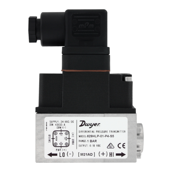
Series 629HLP Differential Pressure Transmitters
Specifications - Installation and Operating Instructions
The Series 629HLP Differential Pressure Transmitters are suitable for measuring
over-pressure, under-pressure, and differential pressure in compatible gases and
liquids with 1% accuracy. The 629HLP is suitable for all measuring tasks in commercial,
industrial or sanitary applications. Its single diaphragm design, allows it to measure
small increment pressure changes, and converts them to a linear analog output signal
from 4-20 mA or 0-10VDC.
Installation
Location/Mounting
The transmitter can be mounted in various locations as long it is not subject to
excessive vibration, shock, or extreme temperature (see Specifications). The tubing
feeding the pressure port may be of any length, but longer lengths will increase the
response time slightly. Avoid sharp bends, and depending on the vibration and shock
it is recommended to install attenuating components.
To facilitate installation, mounting bracket A-629HLP-BKT, is available as accessory.
Position/Orientation
The transmitter is not sensitive to installation position. However, factory calibration
is performed with the unit in a vertical position and horizontal pressure connections.
Pressure Connections
Pressure connections are 1/4˝ female NPT or 1/4˝ female BSPT. Avoid excess sealant
and ensure the pressure passages are not blocked.
The piping should allow removal and reinstallation of the transmitter without shutdown
of the pressure system. Especially in applications where the differential pressures are
measured at high static line pressures that are above the overpressure limit of the
transmitter. It is recommended to install the 629HLP transmitter with a 3 way manifold
and a bypass valve (see Figure 1).
The manifold with the bypass valve will help to balance the pressure between the low
and high side of the transmitter.
Dwyer offers a 3-way Block manifold option for this purpose.
Close the drain valve and open the bypass valve. Then both shutoff valves are opened
to apply line pressure equally to both sides of the transducer. Finally, close the bypass
valve. To remove the transducer, open the bypass valve, close the shutoff valves and
open the drain valve.
SHUTOFF VALVES
SHUTOFF VALVES
PRESSURE MEASUREMENT SOURCE
DWYER INSTRUMENTS, INC.
P.O. BOX 373 • MICHIGAN CITY, INDIANA 46360, U.S.A.
DRAIN VALVE
Figure 1
DIN CABLE
INLET
1-21/32
Ø.418 I.D.
[42.00]
3-1/4
[82.40]
2-3/16
[55.40]
2-7/16 [62.00]
2-41/64 [67.00]
SPECIFICATIONS
Service: Compatible gases or liquids.
Wetted Material: 304 SS.
Housing Material: ABS.
Enclosure Rating: IP65.
Accuracy: ±1% from -5 to 60°C (23 to 140°F).
Stability: ±1% FS/year.
Temperature Limits: Ambient: -10 to 60°C (14 to 122°F); Process: -10 to 80°C (14
to 176°F).
Relative Humidity: 10% to 90% non-condensing.
Installation Position: Not position sensitive.
Pressure Limits: See Pressure Range Limits chart.
Burst Pressure: See Pressure Range Limits chart.
Static Pressure Limits: See Pressure Range Limits chart.
Output Signal: 4-20 mA, 0-10 VDC.
Response Time: 50 ms.
Rated Supply Voltage: 0-10 VDC Output: 12-36 VDC or 12-32 VAC (@ Max load
of 2k Ω) 4-20 mA output: 8-36 VDC.
Max Loop resistance: (Supply Voltage – 8 V) / 0.02 for 4-20 mA output.
Power Consumption: V
= 13 mA max, I
out
Electrical Connections: Form A DIN 43650.
Process Connections: 1/4˝ female NPT, 1/4˝ female BSPT.
Weight: 1 lb 4 oz (567 g).
Approvals: CE, RCM.
MODEL CHART
Example
629HLP -01 -P2 -S1 -FC
Series
629HLP
Range
01
02
04
06
15
30
60
90
Process
P2
Connections
P4
Output Signal
Options
Note: PSI ranges available upon request. Contact factory for details.
PRESSURE RANGE LIMITS
Pressure
Maximum Static
*Maximum Differential
Range
Pressure
Over Pressure
0 to 1 bar
25 bar
5 bar
0 to 2.5 bar
25 bar
5 bar
0 to 4 bar
25 bar
12 bar
0 to 6 bar
25 bar
12 bar
0 to 15 psi
360 psi
70 psi
0 to 30 psi
360 psi
70 psi
0 to 60 psi
360 psi
174 psi
0 to 90 psi
360 psi
174 psi
Note: *The differential pressure limit, between high and low ports, that the
transmitter can withstand without affecting transmitter performance
**Differential pressures between high and low ports that exceed overpressure limits
will result in permanent diaphragm deformation, and any pressure higher than the
burst pressure limits will rupture the diaphragm.
Phone: 219/879-8000
Fax: 219/872-9057
Bulletin P-629HLP
1-3/16
[30.00]
1/4 NPT OR
1/4 BSPT
= 24 mA max.
out
629HLP-01-P2-S1-FC
Differential pressure transmitter
0 to 1 bar
0 to 2.5 bar
0 to 4 bar
0 to 6 bar
0 to 15 psi
0 to 30 psi
0 to 60 psi
0 to 90 psi
1/4˝ female NPT
1/4˝ female BSPT
S1
4-20 mA
S5
0-10 VDC
FC
Factory calibration
NIST
NIST certificate
**Burst Differential
Pressure
8 bar
8 bar
18 bar
18 bar
115 psi
115 psi
260 psi
260 psi
www.dwyer-inst.com
e-mail: info@dwyermail.com
Advertisement

Related Manuals for Dwyer Instruments 629HLP Series


Summary of Contents for Dwyer Instruments 629HLP Series
- Page 1 PRESSURE MEASUREMENT SOURCE will result in permanent diaphragm deformation, and any pressure higher than the burst pressure limits will rupture the diaphragm. Figure 1 DWYER INSTRUMENTS, INC. Phone: 219/879-8000 www.dwyer-inst.com P.O. BOX 373 • MICHIGAN CITY, INDIANA 46360, U.S.A. Fax: 219/872-9057...
- Page 2 Wire as shown in Figure 4a or Figure 4b depending on the output signal required. WIRING - VOLTAGE OUTPUT PWR (+) COM (-) Figure 4a (0-10 VDC) ©Copyright 2019 Dwyer Instruments, Inc. Printed in U.S.A. 10/19 FR# 443277-20 Rev. 3 DWYER INSTRUMENTS, INC. Phone: 219/879-8000 www.dwyer-inst.com...
Need help?
Do you have a question about the 629HLP Series and is the answer not in the manual?
Questions and answers