Advertisement
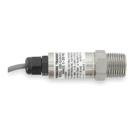
Series 626 & 628 Pressure Transmitters
Specifications - Installation and Operating Instructions
-CH Conduit Housing
LIQUID TIGHT FITTING
CORD DIAMETER RANGE
.200 to .350 (5.08 to 8.89)
1-3/32
[27.76]
The Series 626 & 628 Pressure Transmitters converts a single positive pressure
into a standard 4 to 20 mA output signal. The Series 626 and 628 can be used to
accurately measure compatible gases and liquids; Series 626 full scale accuracy
is 0.25%; Series 628 full scale accuracy is 1.0% (see specifications). Designed for
industrial environments with a NEMA 4X (IP66) housing, this transmitter resists most
effects of shock and vibration.
Caution: Do not exceed specified supply voltage ratings. Permanent
damage not covered by warranty will result. This device is not designed
for 120 or 240 volt AC operation. Use only on 13 to 30 VDC.
Pressure Ranges
Pressure
Maximum
Over
Range
Pressure
Pressure
0-15 psia
30 psia
45 psia
15-0 psia
30 psia
45 psia
0-30 psia
60 psia
90 psia
0-50 psia
100 psia
150 psia
0-100 psia
200 psia
300 psia
0-200 psia
400 psia
600 psia
0-300 psia
600 psia
900 psia
0-5 psig
10 psig
50 psig
0-15 psig
30 psig
150 psig
0-30 psig
60 psig
300 psig
0-50 psig
100 psig
300 psig
0-100 psig
200 psig
500 psig
0-150 psig
300 psig
750 psig
0-200 psig
400 psig
1000 psig
0-300 psig
600 psig
1500 psig
0-500 psig
1000 psig
2500 psig
0-1000 psig
2000 psig
5000 psig
0-1500 psig
3000 psig
5000 psig
0-2000 psig
4000 psig
5000 psig
0-3000 psig
6000 psig
7500 psig
0-5000 psig
7500 psig
10000 psig
0-8000 psig
10000 psig
12000 psig
DWYER INSTRUMENTS, INC.
P.O. BOX 373 • MICHIGAN CITY, INDIANA 46360, U.S.A.
1-9/32
[32.54]
2-15/16 [74.61]
OPTIONAL 1/4 NPT
FEMALE FITTING
3-1/2 [88.90]
1/4 NPT
MALE FITTING
1/4 NPT
3/4
[19.05]
5-1/2 [139.70]
-GH General Purpose Housing
1/4 NPT
7/8 [22.23]
HEX
SPECIFICATIONS
Service: Compatible gases and liquids.
Wetted Materials: Type 316 SS.
Accuracy: 626: 0.25% FS, 0.20% RSS;
628: 1.0% FS, 0.5% RSS; 626 absolute
ranges: 0.5% FS, 0.35% RSS. (Includes
linearity, hysteresis, and repeatability).
Temperature Limit: 0 to 200°F (-18 to
93°C).
Compensation Temperature Range: 0
to 175° (-18 to 79°C).
Thermal Effect: 626: ±0.02% FS/°F.
628: ±0.04% FS/°F (includes zero and
span).
Pressure Limits: See table.
Power Requirements: 10-30 VDC (for
4 to 20 mA, 0-5, 1-5, 1-6 VDC outpus);
13-30 VDC (for 0-10, 2-10 VDC outputs);
5 VDC ±0.5 VDC (for 0.5-4.5 VDC ratio-
metric output).
Output Signal: 4 to 20 mA, 0-5 VDC,1-5
VDC, 0-10 VDC, or 0.5-4.5 VDC.
Response Time: 300 ms.
INSTALLATION
1. Location: Select a location where the temperature of the transmitter will be
between 0 and 175°F (-18 to 79°C). Distance from the receiver is limited only by
total loop resistance. The tubing or piping supplying pressure to the unit can be
practically any length required but long lengths will increase response time slightly.
2. Position: The transmitter is not position sensitive. However all standard models
are originally calibrated with the unit in a position with the pressure connection
downward. Although they can be used at other angles, for best accuracy it is
recommended that units be installed in the position calibrated at the factory.
3. Pressure Connection: Use a small amount of plumber's tape or other suitable
sealants to prevent leaks. Be sure the pressure passage inside the port is not
blocked.
4. Electrical Connections
Wire Length - The maximum length of wire connecting the transmitter and receiver
is a function of wire size and receiver resistance. Wiring should not contribute more
than 10% of the receiver resistance to total loop resistance. For extremely long
runs (over 1000 feet), choose receivers with higher resistance to minimize the size
and cost of connecting leads. Where wiring length is under 100 feet, wire as small
as 22 AWG can be used.
Phone: 219/879-8000
Fax: 219/872-9057
Bulletin E-111
055/64 [21.83]
2-27/64 [61.52]
3-13/64 [81.36]
Loop Resistance: 0-1000 Ohms max.
R max = 50 (Vps-10) Ohms (4 to 20 mA
output), 5K Ohms (0-5, 1-5, 1-6, 0-10,
2-10, 0.5-4.5 VDC output).
Current Consumption: 38 mA
maximum (for 4 to 20 mA output); 10 mA
maximum (for 0-5, 1-5, 1-6, 0-10, 2-10,
0.5-4.5 VDC output); 140 mA maxumum
(for all 626/628/629-CH with optional
LED).
Electrical Connections: Conduit
Housing (-CH): terminal block, 1/2˝
female NPT conduit; General Purpose
Housing (-GH): cable DIN EN 175801-
803-C.
Process Connection: 1/4˝ male or
female NPT and BSPT.
Enclosure Rating: NEMA 4X (IP66).
Mounting Orientation: Mount in any
position.
Weight: 10 oz (283 g).
Agency Approvals: CE.
www.dwyer-inst.com
e-mail: info@dwyermail.com
Advertisement
Table of Contents

Related Manuals for Dwyer Instruments 626 series


Summary of Contents for Dwyer Instruments 626 series
- Page 1 (over 1000 feet), choose receivers with higher resistance to minimize the size and cost of connecting leads. Where wiring length is under 100 feet, wire as small as 22 AWG can be used. DWYER INSTRUMENTS, INC. Phone: 219/879-8000 www.dwyer-inst.com P.O.
- Page 2 CURRENT (4 to 20 mA) OUTPUT OPERATION PRESS AND HOLD TO PRESS TO ZERO THE DISPLAY An external power supply delivering 10-30 VDC with minimum current capability of DISPLAY 40 mA DC (per transmitter) is required to power the control loop. See Figure A for SPAN THE GAGE’S PRESSURE...
- Page 3 VOLTAGE (0-5, 1-5, 0-10, 1-6 or 2-10 VDC) OUTPUT OPERATION RATIOMETRIC (0.5-4.5 VDC) OUTPUT OPERATION (Other outputs contact the factory) See Figure G for connection of the power supply, (Other outputs contact the factory) See Figure K for connection of the power supply, transmitter and receiver.
- Page 4 __________________________________________________________________________________________________________________________________________ __________________________________________________________________________________________________________________________________________ __________________________________________________________________________________________________________________________________________ __________________________________________________________________________________________________________________________________________ __________________________________________________________________________________________________________________________________________ __________________________________________________________________________________________________________________________________________ __________________________________________________________________________________________________________________________________________ __________________________________________________________________________________________________________________________________________ __________________________________________________________________________________________________________________________________________ ©Copyright 2018 Dwyer Instruments, Inc. Printed in U.S.A. 2/18 FR# 443271-00 Rev.21 DWYER INSTRUMENTS, INC. Phone: 219/879-8000 www.dwyer-inst.com P.O. BOX 373 • MICHIGAN CITY, INDIANA 46360, U.S.A. Fax: 219/872-9057 e-mail: info@dwyermail.com...
Need help?
Do you have a question about the 626 series and is the answer not in the manual?
Questions and answers