Table of Contents
Advertisement
Quick Links
Advertisement
Table of Contents

Related Manuals for Garmin CR 1522


Summary of Contents for Garmin CR 1522
- Page 1 CR 1522 Marine Chart Radar Owner’s Manual...
- Page 2 All rights reserved. Under the copyright laws, this manual may not be copied, in whole or in part, without the written consent of Garmin. Garmin reserves the right to change or improve its products and to make changes in the content of this manual without the obligation to notify any person or organization of such changes or improvements.
-
Page 3: Table Of Contents
TABLE OF CONTENTS CHAPTER 1 INTRODUCTION ������������������������������������������������������������������������� 5 A Brief History of Marine Radars ..................5 1.1.1 Basic Principles of Radars ..................5 1.1.2 Development of Marine Radars ................5 1.1.3 Determining the Bearing ................... 5 1.1.4 Determining the Range ..................... 5 1.1.5 Displaying Relative Positions ................... - Page 4 1.8.2 Updating the Software .................... 26 Protective Cover ......................26 1.10 Garmin Support Center ....................27 1.10.1 Registering Your Device ..................27 CHAPTER 2 GETTING STARTED ����������������������������������������������������������������� 29 Basic Operations ......................29 2.1.1 Powering On/Off ..................... 29 2.1.2 Transmitting ......................29 2.1.3 Putting the Radar on Standby ................29 2.1.4...
- Page 5 2.6.5 TT Symbols ......................38 Navigation Chart ......................39 2.7.1 Navigation Chart Interface ..................39 2.7.2 Navigating to a Point ....................40 2.7.3 Viewing Information ....................40 F1-F4 Shortcuts ......................41 2.8.1 Using a Shortcut Function ..................41 2.8.2 Swapping an Assigned Function ................41 CHAPTER 3 MENU AND SETTINGS �������������������������������������������������������������...
- Page 6 Chart Setup ........................53 3.7.1 Selecting the Chart Orientation ................54 3.7.2 Personalizing the Chart ..................54 Navigation Info ........................54 3.8.1 Navigating to Coordinates ..................54 3.8.2 Managing Navigational Data.................. 54 3.8.3 Managing Tracks ....................55 Navigation Chart Appearance ..................55 3.9.1 Customizing Chart Layers ..................
-
Page 7: Chapter 1 Introduction
CHAPTER 1 INTRODUCTION WARNING See the Important Safety and Product Information in the Installation Instructions for product warnings and other important information. All route and navigation lines displayed on the device are intended to provide general guidance to identify proper channels, and are not intended to be strictly followed. Always refer to the navaids and conditions on the water when navigating to avoid groundings or hazards that could result in vessel damage, personal injury, or death. -
Page 8: Displaying Relative Positions
1.1.5 Displaying Relative Positions The calculated relative positions of detected targets are plotted on the radar display with the own ship position usually at the center. The plot is refreshed as the antenna rotates, and the relative motions and speeds of targets can also be displayed. Aerial View Radar Display Specifications... -
Page 9: Nmea 2000 Pgn Information
NMEA 2000 draw 75 mA max. SW version (as of Dec 2019) * Depending on radar scanner model. ** The device is protected against powerful jets of water, and withstands incidental exposure to water of up to 1 m for up to 30 minutes. For more information on water rating, go to Garmin.com/waterrating. 1.2.1 NMEA 2000 PGN Information Type Description Transmit 059392... -
Page 10: Nmea 0183 Information
Type Description Receive 127505 Fluid level 127508 Battery status 129038 AIS class A position report 129039 AIS class B position report 129040 AIS class B extended position report 129539 GNSS DOPs 129794 AIS class A static and voyage related data 129809 AIS class B “CS”... -
Page 11: Inside The Box
Type Sentence Description Receive Depth Depth below transducer Water temperature Water speed and heading Waypoint location Digital selective calling information Expanded digital selective calling Heading, deviation, and variation Heading, magnetic Wind direction and speed Meteorological composite Wind speed and angle AIS VHF data-link message You can purchase complete information about National Marine Electronics Association (NMEA) format and sentences from: NMEA, Seven Riggs Avenue, Severna Park, MD... -
Page 12: Device Overview
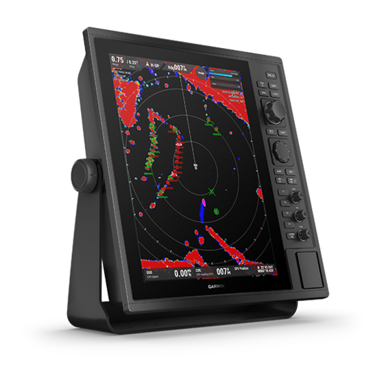
Documentation K00-01227-00 1.3.1 Device Overview The Garmin CR 1522 features a 15-inch XGA display, with a control panel, and 2 SD card slots on the side. The CR 1522 can be bail mounted or flush mounted to your boat. Connection to a marine radar such as GMR Fantom 6 or GMR 24 xHD, is required. 378.3 mm 108.3 mm... -
Page 13: Ports
1�3�2 Ports The ports are located at the back of the device. POWER NMEA0183 GMR RADAR GPS ANT NMEA 0183 NMEA 2000 Ground 1.3.3 Port Pin Definition Power Port Accessory NMEA TXB NMEA RXB Power supply - / Ground Power supply + NMEA TXA Alarm NMEA RXA... -
Page 14: Installation
1.4.1 Typical Configuration The diagram shows a typical configuration of the device. Antenna GPS Antenna NMEA 0183 Network Gyro/Heading Sensor CR 1522 Rectifier 10–36 VDC 115/230 VAC Power Supply Power Supply 1.4.2 Tools Needed • Bail mount: drill and drill bits appropriate for the surface and hardware • Flush mount: drill and 14 mm (9/16 in), 6 mm (1/4 in) and 3.6 mm (9/64 in) drill bits with nut plates, or 3.2 mm (1/8 in) drill bit without nut plates... -
Page 15: Mounting Considerations
• #2 Phillips screwdriver • Jigsaw or rotary tool • File and sandpaper • Marine sealant (recommended) 1.4.3 Mounting Considerations NOTICE This device should be mounted in a location that is not exposed to extreme temperatures or conditions. The temperature range for this device is listed in the product specifications. Extended exposure to temperatures exceeding the specified temperature range, in storage or operating conditions, may cause device failure. -
Page 16: Flush Mounting The Device
2 Using a 3 mm (1/8 in) drill bit, drill the pilot holes. 3 Secure the bail mount bracket to the mounting surface using the bail mount screws and washers. 4 Install the bail mount knobs on the sides of the device. 5 Place the device in the bail mount bracket, and tighten the bail mount knobs. 1.4.5 Flush Mounting the Device NOTICE... - Page 17 11 Starting in one corner of the template, place a nut plate over the larger hole drilled in the previous step. If you are using a nut plate, the smaller hole on the nut plate should line up with the smaller hole on the template.
-
Page 18: Radar Unit Installation
21 If you have access to the back of the device, apply marine sealant around the cutout. 22 Place the device into the cutout. 23 Secure the device to the mounting surface using the included M4 screws 24 Wipe away all excess marine sealant. 25 Install the trim caps by snapping them in place around the edges of the device. -
Page 19: Cable Considerations
When installing the cables, you should observe these considerations: • Cutting the Garmin Marine Network cable is not recommended, but a field install kit can be purchased from Garmin or a Garmin dealer if cutting the network cable is necessary. -
Page 20: Performance Monitor Notices
1.5.4 Performance Monitor Notices The performance monitor should be installed at around 10 cm from the radar. • For open-array type radars, the performance monitor should be installed at the same height as the antenna. • For dome type radars, the performance monitor should be installed at the same height as the radar. -
Page 21: Gps Antenna Considerations
When connecting a GMR radar module to this device, observe these considerations. • A Garmin Marine Network cable must be used. • Third-party CAT5 cable and RJ45 connectors must not be used. • Additional Garmin Marine Network cables and connectors are available from your Garmin dealer. 1.6.5... -
Page 22: Nmea 0183 Connection Considerations
• There is one internal NMEA 0183 input port (RX port) and one internal NMEA 0183 output port (TX port) on the included NMEA 0183 data cable. You can connect one NMEA 0183 device to the internal RX port to input data to this Garmin device, and you can connect up to three NMEA 0183 devices in parallel to the internal TX port to receive data output by this Garmin device. - Page 23 • The internal NMEA 0183 ports and communication protocols are configured on the connected Garmin device. See the NMEA 0183 section of the chartplotter owner’s manual for more information. NMEA 0183 Device Connections This diagram illustrates two-way connections for both sending and receiving data.
- Page 24 Single-Ended NMEA 0183 Device Connections Item Description Power source Power / NMEA 0183 cable NMEA 0183 device NMEA 0183 Device Item Garmin Wire Color Garmin Wire Function Wire Function Power Power Black Power ground Power ground Violet Brown Blue Gray •...
- Page 25 In this example, the NMEA 0183 device is sending data to the chartplotter. Item Description DC Power supply / battery Power / NMEA 0183 cable NMEA 0183 device NMEA 0183 Device Item Garmin Wire Color Garmin Wire Function Wire Function Power Power Black Power ground Power ground...
-
Page 26: Lamp And Horn Connections
1.6.7 Lamp and Horn Connections The device can be used with a lamp, a horn, or both, to sound or flash an alert when the chartplotter displays a message. This is optional, and the alarm wire is not necessary for the device to function normally. When connecting the device to a lamp or horn, observe these considerations. • The alarm circuit switches to a low-voltage state when the alarm sounds. •... -
Page 27: Control Panel
Control Panel Press: Turns power on; adjusts the backlight or the color mode. Hold: Turns power off. Press: Sets the radar to standby; Press: Selects display modes. transmits radar pulse. Press: Moves focus (highlight) to Press: Opens or closes the menu. the next option. Turn: Selects a range in radar modes;... -
Page 28: Capturing A Screenshot
2 Open the downloaded file, and follow the on-screen instructions to copy the software update to an SD card. A Garmin folder containing the software update is created on the SD card. 3 Power on the device, and insert the SD card into one of the card slots. NOTE: In order for the software update instructions to appear, the device must be fully booted before the card is inserted. -
Page 29: 1.10 Garmin Support Center
The device creates a file named GarminDevice.xml in the Garmin folder on the SD card. 3 Remove the SD card. 4 Insert the SD card into your computer. 5 On your computer, go to my.garmin.com. 6 Follow the on-screen instructions to download, install, and open the Garmin Express application. 7 Select Add a Device. - Page 30 CHAPTER 1 INTRODUCTION...
-
Page 31: Chapter 2 Getting Started
2.1.1 Powering On/Off Press [ ] to turn on the device. The GARMIN logo appears, and the control panel lights up. A countdown timer will appear if the magnetron is warming up, after which a Ready to Transmit message will appear. -
Page 32: Display Modes
Display Modes 2.2.1 Typical Views The following views are typical examples of how each display mode looks like. Professional Basic Dual Professional mode shows the Basic mode shows less data Dual Range mode splits Basic full set of data on the screen, on the screen with a larger mode to two separate radar and shows two TT target... -
Page 33: Radar Interface Overview
2.2.2 Radar Interface Overview The following is an overview of the radar interface, using the Professional mode as an example. North pointer & orientation Heading Heading line Main knob control Range / ring interval Gain level Sea clutter reduction 0�75 GAIN Auto High Rain clutter reduction... -
Page 34: Adjusting The Range And Zoom
2.3.2 Adjusting the Range and Zoom The range of the radar signal indicates the length of the pulsed signal transmitted and received by the radar. As the range increases, the radar transmits longer pulses in order to reach distant targets. Closer targets, especially rain and waves, also reflect the longer pulses, which can add noise to the radar screen. You can also zoom in and out to adjust the visible range on the radar screen. -
Page 35: Adjusting Rain Clutter Reduction
TIP: Adjust the sea clutter reduction to a level such that some clutter remains visible on the radar display. If all clutter is removed, smaller targets may be missed and become a threat to your boat. 2.4.3 Adjusting Rain Clutter Reduction Rain Clutter are echoes reflected off rain, snow, and hail in the same manner as normal targets. -
Page 36: Selecting Data Panels
2.5.2 Selecting Data Panels Data panels around the radar display can be selected for additional settings. • Press [FOCUS] to sequentially highlight data panels, and press [SELECT] to jump to settings related to the data panel. 0�75 GAIN Auto High / 0�25 H-UP Zoom... -
Page 37: Dropping Reference Points
• Hold [MARK] to open the Waypoints list: Waypoints Symbol Name Distance Bearing (Boat) Review Sort/Filter > 0001 0�78 Search 0002 0.62 New Waypoint 0003 1.20 Navigate To > 0004 3.28 0005 0.97 0.83 0006 7.94 0007 0008 8.06 0009 4.11 0010 0.35... -
Page 38: Measuring Range And Bearing Between Two Points
Hiding/Editing the VRM/EBL To hide or adjust the reference points and the respective lines: 1 Press [VRM EBL 1] / [VRM EBL 2] to hide the respective lines. 2 Press [VRM EBL 1] / [VRM EBL 2] again and use the control pad to adjust the position of the reference point. -
Page 39: Capturing A Screenshot
2.5.9 Capturing a Screenshot From any screen, hold [SELECT] for 3 seconds, a screenshot (in PNG format) will be saved to your inserted SD card (see 1.8). 2.5.10 Acknowledging and Silencing an Alarm • When an alarm sounds, you can acknowledge and silence the alarm by pressing [ALARM ACK]. • You can hold [ALARM ACK] to open the Alarms menu (see 3.5). Simplified Target Tracking (TT) WARNING Do not rely solely on the Simplified Target Tracking (TT) feature for collision avoidance. -
Page 40: Acquiring Targets Manually
2.6.2 Acquiring Targets Manually To acquire a TT target manually, use the control pad to move the cursor to a target, and either press [ACQ] or press [SELECT] > Acquire Target to acquire the cursor-located echo as a TT target. 2.6.3 Acquiring Targets Automatically To automatically acquire TT targets, press [MENU] >... -
Page 41: Navigation Chart
To select a TT target, move the cursor near the TT symbol, and press [SELECT]. Select Review Target from the pop-up menu to view its information or remove the target. Information, including the range (RNG), bearing (BRG), GPS speed (SOG), GPS heading (COG), closest point of approach (CPA), and time to closest point of approach (TCPA), of the two most recently selected TT targets are displayed at the bottom of the screen. Press [FOCUS] to highlight the data panel and press [SELECT] to review or remove the target. -
Page 42: Navigating To A Point
2.7.2 Navigating to a Point You can select a point on the chart and set a course to the destination. Navigating Directly to a Destination 1 Use the control pad to move the cursor to a point you would like to navigate to. 2 Press [SELECT] >... -
Page 43: F1-F4 Shortcuts
Local Services You can view local services information. 1 Use the control pad to invoke the cursor. 2 Press [SELECT] > Information > Local Services. F1-F4 Shortcuts The F1 to F4 shortcut buttons are assigned to various functions for quick accesses. Mode Professional Basic... - Page 44 CHAPTER 2 GETTING STARTED...
-
Page 45: Chapter 3 Menu And Settings
Range RINGS ECHO TRAILS 30 SEC. RAIN ECHO THRESHOLD 86% CROSSTLK REJ: Off TIMED TX Off MOTIONSCOPE: On OFF CENTER Off CHAPTER 3 MENU AND SETTINGS TARGET SIZE: NML Accessing the Menu The menu contains more advanced or less frequently used features and settings. •... -
Page 46: Selecting Two Ranges
• Select Course Up to orient the radar display so the course (the direction your vessel is moving) always points straight up. 3.2.2 Selecting Two Ranges The radar can transmit two pulses set to different ranges. Select Dual Range to toggle the second range channel on/off. With Dual Range toggled on, select Range Channel to select a range channel to display (Range A or Range B). -
Page 47: Echo Trails
0�75 / 0�25 H-UP Range RINGS ECHO TRAILS 30 SEC. RAIN ECHO THRESHOLD 86% 3.2.4 Echo Trails CROSSTLK REJ TIMED TX Off The radar shows movements of targets on the radar display by keeping previous MOTIONSCOPE OFF CENTER Off TARGET SIZE: instances of the echoes on the display in a different color (deep blue versus red by Radar Setup>... -
Page 48: Adjusting Gain
3.3.1 Adjusting Gain You can control the level of detail and noise of the echoes shown on the radar display by adjusting gain (see 2.4.1 for more information). Select Gain and make a selection: • Manual allows you to adjust gain manually using the main knob or the control pad. •... -
Page 49: Selecting Target Size
With MotionScope™ toggled on, select Sensitivity and use the main knob to change the speed threshold for target highlighting. A higher setting highlights slower targets, and a lower setting highlights only faster targets. NOTE: Only available on Fantom models. 3.3.5 Selecting Target Size You can adjust how the resolution of the radar image by selecting the size of targets. -
Page 50: Managing Other Vessels
3.4.1 Managing Other Vessels You can view/sort/filter a list of vessels, review individual vessels, or clear TT targets. Select List to open the list of other vessels. Other Vessels MMSI Name Bearing Distance Speed Group Review Show TT051 TT Target 51 1380 Sort By > TT057 TT Target 57 1387 Filter By > 5437 TT056 TT Target 56... -
Page 51: Adjusting Vector Times
Select AIS to toggle AIS tracking on/off. CAUTION If turned off, all AIS functionality, including AIS vessel targeting, tracking, collision alarms from AIS vessels, and the display of information about AIS vessels, will be disabled. With AIS toggled on: • Select AIS Group to view and manage targets by 3 AIS groups. •... -
Page 52: Setting Up Guard Zones
Including/Excluding TT Targets With Collision Alarm turned On, select TT Alarm and make a selection: • Select Off to exclude TT targets. • Select On to include TT targets. • Select Dangerous Only to sound the alarm only for dangerous targets. Adjusting Alarm Sensitivity •... -
Page 53: Setting Up Boundaries
TARGET SIZE: NML 3.5.3 Setting Up Boundaries You can set up custom boundaries that alert you if your boat or other vessels enter or exit a boundary. Select Boundaries to open a list of boundaries. Boundaries Color Name Display Alarm Dist�/Brg�... -
Page 54: Radar Appearance
Radar Appearance Press [MENU] > Appearance in radar modes to customize the appearance of your radar display. NOTE: The menu is specific to Professional, Basic, Dual Range, and Radar Overlay modes. Menu Radar Appearance Radar Setup Color Scheme Echo Tuning Echo Color Multi Other Vessels Brightness >... -
Page 55: Using Pi Lines
3.6.5 Using PI Lines Parallel Indexing (PI) Lines can help you navigate through congested water or narrow canals, keeping your vessel on track, at a fixed distance from shorelines or edges of a traffic lane. With PI Lines toggled on: • Select Display Side > One to set up a PI line on the starboard side of your vessel, or Both to set up PI lines on both sides of your vessel. •... -
Page 56: Selecting The Chart Orientation
3.7.1 Selecting the Chart Orientation The chart can be oriented in three different ways. Select Orientation and select an orientation: • Select Head Up to orient the chart so the heading always points straight up. • Select North Up to orient the chart so north always points straight up. •... -
Page 57: Managing Tracks
3.8.3 Managing Tracks A track is a recording of the path of your boat. The track being recorded is the active track. Select Tracks and choose one of the settings: • Select Active Track Options to toggle on active tracking. With the option toggled on: •... -
Page 58: Editing Data Panels
3.9.2 Editing Data Panels You can change the layout of the overlaying data panels. Select Edit Overlays > Data and make a selection: • Top Bar displays 6 data on the top of the screen. • Double Top Bar displays 8 data in 2 rows on the top of the screen. •... -
Page 59: 3.10.2 Preferences
3.10.2 Preferences Press [MENU] > Preferences to adjust user preferences. Menu Preferences Settings Units > Language English System Preferences Navigation > Communications Keyboard Layout QWERTY F1-F4 Presets My Vessel > HL Off Mode Data Management Full Screenshot Capture Installation • Select Units to adjust the System Units, North Reference, Variance, Position Format Map Datum, Time Format, and Time Zone. -
Page 60: 3.10.4 My Vessel Settings
3.10.4 My Vessel Settings Press [MENU] > My Vessel to adjust your vessel’s settings, such as anchor height and fuel capacity. Menu My Vessel Settings Depth and Anchoring > Temperature Offset System Preferences Calibrate Water Speed > Communications Fuel Capacity My Vessel Data Management Installation... - Page 61 • Select Front of Boat to set the orientation corresponding to the front of your vessel. • Select No Transmit Zone 1 / No Transmit Zone 2 to toggle the no transmit zone on/ off. A no transmit zone is a sector between two bearings. With a no transmit zone toggled on: 1 Select Adjust No Transmit Zone.
- Page 62 CHAPTER 3 MENU AND SETTINGS...
-
Page 63: Chapter 4 False Echoes
CHAPTER 4 FALSE ECHOES False echoes are echoes appearing at positions where there is no target. False echoes occur occasionally as a result of the antenna receiving signals reflected off secondary objects. The phenomenon can be reduced but it takes some experience to recognize the distinct patterns of these echoes. There are several types of false echoes, you should familiarize yourself with the appearances of each type of false echoes, and the situations in which each type of false echoes tends to occur. -
Page 64: Indirect Echoes
Indirect Echoes Echoes may return indirectly through multiple reflections off surrounding objects. Indirect echoes would appear as a target at the same range as the direct echo but at the bearing from which the indirect echo was received. Indirect echoes usually have abnormal shapes and movements. False Echo False Echo Blind and Shadow Sectors Large or tall objects may block the path of radar beams and form a blind or shadow sector. -
Page 65: Chapter 5 Appendices
Make sure the Lock switch is slid up to the unlock Memory card is write protected. position. The device is unable to access the internal memory. Database Error Please contact Garmin Support. Radar Error Code: (error code) Please refer to the field service manual. Check the power and network connections on the Radar Service Lost radar and the radar display. -
Page 66: Declaration Of Conformity
97080 Würzburg, Germany Type of Equipment: Portrait Radar/Sonar Display Model Number(s): A03785 (CR 1522, CR 1523, CS 1522, CS 1523) The undersigned does hereby declare that the equipment complies with the above Directives Jamie Wiltshire Quality Supervisor Garmin (Europe) Ltd. -
Page 67: Menu Tree
Menu Tree - Orientation - Scanner - Dual Range - Range Channel - Rotation Speed - Time Radar Setup (Radar) - Echo Trails - Clear Trails - TT - Timed Transmit - Stdby Time - Transmit Time - Radar To Standby - Gain - Sea Clutter - Rain Clutter... - Page 68 - Collision Ararm - TT Alarm - Range - Time To - Guard Zone 1 (Radar) - Adjust Zone Area - Guard Zone 2 (Radar) - Adjust Zone Area - Boundaries - Type - Arrival - Activation Alarms - Change Time - Navigation - Anchor Drag - Off Course - Change Distance - Clock - Change Time...
- Page 69 - Navigation - Compass Tape - Beeper - Sounds and Display - Backlight - Color Mode - GPS - Garmin Devices - Reset Default Settings - Reset - Delete User Data System - System Information - Software Information - Event Log...
- Page 70 - Port Types - NMEA Output 1 - NMEA Output 2 - Sounder - Router - Output Sentences - System - Garmin - NMEA 0183 Setup - Position Precision - XTE Precesion - Waypoint IDs - MMSI Communications - Restore Defaults...
- Page 71 - File Type - Save to Card - Data Transfer - Merge from Card - Replace from Card - Delete File - User Data - Waypoints - Routes - Active Track Data Management - Delete User Data - Saved Tracks - Owner’s Manual - Boundaries - Image Viewer...
- Page 72 CHAPTER 5 APPENDICES...
- Page 74 Garmin International, Inc. 1200 East 151st Street, Olathe, Kansas 66062, USA Garmin (Europe) Ltd. Liberty House, Hounsdown Business Park, Southampton, Hampshire, SO40 9LR, UK Garmin Corporation No. 68, Zhangshu 2nd Road, Xizhi Dist., New Taipei City, 221, Taiwan R-R-GRm-A03785 M/N: A03785...
Need help?
Do you have a question about the CR 1522 and is the answer not in the manual?
Questions and answers