
Related Manuals for Psion Teklogix 8515


Summary of Contents for Psion Teklogix 8515
- Page 1 8515 Vehicle-Mount Computer User Manual January 28, 2010 P/N 8100132.B ISO 9001 Certified Quality Management System...
- Page 2 2100 Meadowvale Boulevard, Mississauga, Ontario, Canada L5N 7J9 http://www.psionteklogix.com This document and the information it contains is the property of Psion Teklogix Inc., is issued in strict confidence, and is not to be reproduced or copied, in whole or in part, except for the sole purpose of promoting the sale of Psion Teklogix manufactured goods and ser- vices.
- Page 3 Return-To-Factory Warranty Psion Teklogix Inc. provides a return to factory warranty on this product for a period of twelve (12) months in accordance with the Statement of Limited Warranty and Limitation of Liability provided at: www.psionteklogix.com/warranty The warranty on Psion Teklogix manufactured equipment does not extend to any product that has been tampered with, altered, or repaired by any person other than an employee of an authorized Psion Teklogix service organization.
- Page 4 RoHS-compliant as per the EU directive. Other than as noted below, a Psion Teklogix product that does not have an accompanying RoHS logo signifies that it was placed on the EU market prior to July 1, 2006, and is thereby exempt from the directive.
-
Page 5: Table Of Contents
Microsoft's End User License Agreement ......ix Psion Teklogix Inc. End User License Agreement ......x Approvals and Safety Summary . - Page 6 Resetting the 8515 Vehicle-Mount Computer ........
- Page 7 Trigger Mappings ........... . 72 Psion Teklogix 8515 Vehicle-Mount Computer User Manual...
- Page 8 Enabling Authentication TRAPS ........97 Psion Teklogix 8515 Vehicle-Mount Computer User Manual...
- Page 9 Network Access ............. . .116 8515 Mounting Accessories: Installing the RAM Mounting Kit ......116 6.4.1...
- Page 10 8515 Vehicle-Mount Computer Specifications ........
- Page 11 ..................I Psion Teklogix 8515 Vehicle-Mount Computer User Manual...
-
Page 13: Program License Agreements
NOT FAULT TOLERANT. THE SOFTWARE IS NOT FAULT TOLER- ANT. PSION TEKLOGIX INC. HAS INDEPENDENTLY DETERMINED HOW TO USE THE SOFTWARE IN THE DEVICE, AND MS HAS RELIED UPON PSION TEKLOGIX INC. TO CONDUCT SUFFICIENT TESTING TO DETERMINE THAT THE SOFTWARE IS SUITABLE FOR SUCH USE. •... -
Page 14: Psion Teklogix Inc. End User License Agreement
Agreement. If you do not agree with this Agreement, we do not grant you a license to the Software, and you may not install or use the Software or any accompanying documentation. Psion Teklogix 8515 Vehicle-Mount Computer User Manual... - Page 15 Chapter : Program License Agreements The Software is the property of Psion Teklogix Inc. or its licensors and is protected by copy- right laws and international copyright treaties, as well as other intellectual property laws and treaties. The Software is licensed, not sold. Psion Teklogix Inc. provides the Software and li- censes its use worldwide.
- Page 16 NOT WARRANT OR MAKE ANY REPRESENTATIONS REGARDING THE USE OR THE RESULTS OF THE USE OF THE SOFTWARE IN TERMS OF ITS CORRECT- NESS, ACCURACY, RELIABILITY, USE WITH FUTURE PSION TEKLOGIX DEVICES INTRODUCED, OR OTHERWISE. YOU EXPRESSLY ACKNOWLEDGE AND AGREE THAT USE OF THE SOFTWARE IS AT YOUR SOLE RISK AND YOU ARE RESPONSIBLE FOR INSTALLATION OF THE SOFTWARE ON YOUR COMPUTER.
- Page 17 In such event, you must return or destroy all copies and com- ponent parts of the Software and documentation, as well as any other Psion Teklogix proprietary information in your possession, within fourteen (14) days of the date of termina- tion.
- Page 18 No modifications of this Agreement shall be effective unless in writing and approved by us. You acknowledge that you have read this Agreement, understand it, and that it is the com- plete agreement between you and Psion Teklogix with respect to the subject matter hereof and supersedes all prior agreements, oral or written.
-
Page 19: Approvals And Safety Summary
Warnings to Users ........xx Psion Teklogix 8515 Vehicle-Mount Computer User Manual... - Page 20 Psion Teklogix 8515 Vehicle-Mount Computer User Manual...
-
Page 21: Ce Marking
Dette utstyret er i overensstemmelse med hovedkravene i R&TTE-direktivet (1999/5/EC) fra EU. (Erklæring finnes på: www.psionteklogix.com). Utrustningen uppfyller kraven för EU-direktivet 1999/5/EC om ansluten teleutrustning och ömsesidigt erkännande av utrustningens överensstämmelse (R&TTE). (Förklaringen finns att läsa på: www.psionteklogix.com). Psion Teklogix 8515 Vehicle-Mount Computer User Manual xvii... -
Page 22: Fcc Information To Users
Tämä laite vastaa EU:n radio- ja telepäätelaitedirektiivin (EU R&TTE Directive 1999/5/EC) vaatimuksia. (Julkilausuma nähtävillä osoitteessa: www.psionteklogix.com). Psion Teklogix tímto prohlašuje, že 8515 Vehicle-Mount Computer je ve shodě se základ- ními požadavky a dalšími příslušnými ustanoveními směrnice 1995/5/ES (NV č. 426/2000 Sb.) a Prohlášení... - Page 23 The use of any other configuration requires its own FCC approval. Some equipment in hospitals and aircraft are not shielded from radio fre- quency energy. Do not use the 8515 onboard aircraft, or in hospitals, without first obtaining permission. Do not use near pacemakers. The product may affect the operation of some medically implanted devices such as pacemakers, causing them to malfunc- tion.
-
Page 24: Emissions Information For Canada
Use of additional wiring and attachments not recommended or sold by the manufacturer may result in fire, electric shock or personal injury. • If using an AC adaptor, use only the AC adaptor recommended by manufacturer. Psion Teklogix 8515 Vehicle-Mount Computer User Manual... - Page 25 To reduce risk of electric shock, unplug the vehicle-mount computer from the DC source before attempting any maintenance or cleaning. Warning: Physically disconnect the 8515 from the vehicle battery during battery charging (into AC outlet). Psion Teklogix 8515 Vehicle-Mount Computer User Manual...
-
Page 27: Chapter 1: Introduction
1.2 Text Conventions ........4 1.3 About the 8515 Vehicle-Mount Computer ......4... - Page 28 Psion Teklogix 8515 Vehicle-Mount Computer User Manual...
-
Page 29: About This Manual
Chapter 5: Configuration provides a description of the Windows Embedded CE 5.0 Control Panel and how to use it to configure the 8515, along with the scanners attached to the unit. Chapter 6: Peripheral Devices & 8515 Installations describes the peripherals and accessories available for your 8515. -
Page 30: Text Conventions
About the 8515 Vehicle-Mount Computer The 8515 is a ruggedized vehicle-mount computer, running the Microsoft Windows Embed- ded CE 5.0 operating system. It is intended for use in commercial and industrial applications with a focus on real time wireless data transactions. A wide range of data input capabilities are supported through a variety of imager, RFID and bar code scanner options. - Page 31 2.1 Features of the 8515 ........
- Page 32 Psion Teklogix 8515 Vehicle-Mount Computer User Manual...
-
Page 33: Chapter 2: Basic Checkout
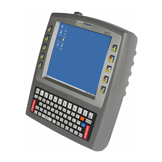
Chapter 2: Basic Checkout Features of the 8515 Features of the 8515 Figure 2.1 Front of the 8515 Vehicle-Mount Computer Antenna Function Keys Function Keys Beeper Power LED Macro Keys Figure 2.2 8515 Ports Speaker/Mic Jack UART (DB-9) Port USB Device Port... -
Page 34: Preparing The 8515 For Operation
Typically the 8515 Vehicle-Mount Computer is configured at the factory and arrives ready for use. Although the 8515 is equipped with an internal Compact Flash slot and a Micro-SD I/O slot, these slots are not intended for user modification. If a device needs to be changed or added in these slots, contact qualified Psion Teklogix personnel. -
Page 35: Important Operating Instructions
C (32 close to 90% Warning: Do not install the 8515 in such a way that the power cable is bent 90 degrees as this may damage the power cable and power cable strain relief. Switching the 8515 On and Off •... -
Page 36: Calibrating The Touchscreen
[BLUE] key is locked ‘on’. Calibrating the Touchscreen If your 8515 touchscreen has never been calibrated or if you find that the stylus pointer is not accurate when you tap on an item, use the Stylus Properties dialog box in the Control Panel to recalibrate the screen. -
Page 37: Data Transfer Between The 8515 And A Pc
Drag and drop files between the 8515 and the PC in the same way that you would between PC drives. • Back up 8515 files to the PC, then restore them from the PC to the hand-held again, if needed, and so on. 2.7.1 Using Microsoft ActiveSync To install ActiveSync, follow the step-by-step instructions provided with the program’s... -
Page 38: Summit Client Utility (Scu) For 802.11B/G Radio
802.11b/g Compact Flash radio module so that it can communi- cate through a wireless LAN effectively and securely. Note: You do not need to reset your 8515 after configuring the Summit DC 802.11 SC (Model RA2041) CF radio. 2.8.1... -
Page 39: Name Servers Tab
3. Tap on the IP Information tab Note: Choosing the Renew button forces the 8515 to renew or find a new IP address. This is useful if, for example, you are out of communication range for a longer period of time and your 8515 is dropped from the network. -
Page 40: Using The Scu To Connect To The Wlan
Appendix B: “SCU for 802.11b/g Radio”. To launch the SCU so that your computer can connect to a wireless LAN: 1. Tap on Start>Programs>Summit>SCU. Figure 2.3 SCU Main Menu 2. Tap on the Profile tab. Radio Attributes Psion Teklogix 8515 Vehicle-Mount Computer User Manual... -
Page 41: 2.8.3.1 Ssid
If you choose Manual WEP, WPA PSK or WPA PSK: • Tap on the WEP/PSK Keys button. For Manual WEP, choose up to four static WEP keys. For PSK, type an ASCII passphrase or hex PSK. Psion Teklogix 8515 Vehicle-Mount Computer User Manual... -
Page 42: Resetting The 8515 Vehicle-Mount Computer
A warm reset closes open applications; any unsaved data is lost. Installed programs and saved data are preserved. Note: You do not need to reset your 8515 after configuring the radio. Psion Teklogix 8515 Vehicle-Mount Computer User Manual... - Page 43 Files and data stored in flash are preserved. Once the OS loads, any executables and cab files in the startup folders are run. The cab files are deleted by the cab file installer unless they are marked read-only. Psion Teklogix 8515 Vehicle-Mount Computer User Manual...
- Page 45 3.6 8515 Indicators........25...
- Page 46 Psion Teklogix 8515 Vehicle-Mount Computer User Manual...
-
Page 47: Chapter 3: Getting To Know The 8515
The backup battery provides one hour of memory backup. For configuration information, please see “Power Properties” on page 74; for specifications, see “Internal Lithium-Polymer Battery” on page 135. The backup battery is not user accessible. It must be replaced by authorized Psion Teklogix personnel. The Stylus The stylus is supplied with a holder with double-sided adhesive tape so that it can be at- tached wherever is most convenient for you. -
Page 48: Activating Modifier Keys
When a modifier key is pressed once, it is displayed in lowercase letters in the taskbar at the bottom of the 8515 screen. For example, if the [CTRL] key is pressed, ctrl key is dis- played at the bottom of the unit screen. Once another key is pressed, the modifier key becomes inactive and disappears from the taskbar. - Page 49 Chapter 3: Getting to Know the 8515 The Keys The Arrow Keys The Arrow keys move the cursor around the screen in the direction of the arrow—up, down, left and right. The cursor is the flashing box or underline character that indicates where the next character you type will appear.
-
Page 50: Function Keys And Macro Keys
Vehicle-Mount Computers are equipped with function keys and macro keys. 3.4.1 Function Keys The 8515 is equipped with a series of 30 function keys divided amongst 10 physical keys, each of which is defined in the application software. There are five keys located on each side of the display. -
Page 51: The Keypad Backlight
The Display The 8515 is equipped with display backlighting to improve character visibility in low light conditions. The backlight switches on when a key is pressed or the touchscreen is tapped. - Page 52 Figure 3.1 Taskbar The taskbar changes dynamically, and only those icons that are applicable are displayed. For example, if a radio is not installed in your 8515, the radio signal icon is not displayed in the taskbar. Windows Start Button You can display the Start Menu by tapping on the Start button in the taskbar.
-
Page 53: Audio Indicators
3.6.3 Audio Indicators The 8515 beeper provides a variety of sounds and can be configured to emit a sound when a key is pressed, a keyboard character is rejected, scan input is accepted or rejected or an oper- ator’s entry does not match in a match field. -
Page 54: Scan Led Indicators
Hold the scanner closer for bar codes with bars that are close together. 3.7.2 Scan LED Indicators External scanners have integrated LED indicators that are not controlled by the 8515. 3.7.3 Troubleshooting If the scanner is not working, investigate the following: •... -
Page 55: Monitoring The Network Connection
Chapter 3: Getting to Know the 8515 Monitoring the Network Connection • Aim at the bar code and press the trigger. The beam expands into a rectangle covering the bar code to properly scan it. The scan beam and a warning indicator are visible until a successful decode is achieved or three seconds have elapsed. -
Page 56: Cleaning The 8515
Chapter 3: Getting to Know the 8515 Cleaning the 8515 3.9.3 Cleaning the 8515 Important: Do not immerse the unit in water. Dampen a soft cloth with mild detergent to wipe the unit clean. • Use only mild detergent or soapy water to clean the computer. -
Page 57: Chapter 4: Windows Embedded Ce
4.5 Using a Dialog Box ........45 Psion Teklogix 8515 Vehicle-Mount Computer User Manual... - Page 58 Psion Teklogix 8515 Vehicle-Mount Computer User Manual...
-
Page 59: Navigating In Windows Embedded Ce 5.0 And Applications
If the touchscreen is not registering your screen taps accurately, it may need recalibration. Refer to “8515 Indicators” on page 25. Each 8515 Vehicle-Mount Computer is equipped with a stylus—a pointing tool that looks like a pen—that is used to select objects on the touchscreen. -
Page 60: Working With Files, Folders, And Programs
Go to Start Menu [BLUE][0] Keep in mind that unlike a desktop computer, the 8515 does not support key chording (pressing two keys at the same time). You must press one key followed by the next in se- quence. Refer to “Working With Files, Folders, and Programs” below for additional details about keyboard navigation. -
Page 61: The Startup Desktop
Use the arrow keys to highlight the icon you want to open or launch. • Press [ENTER]. The Startup Desktop When the 8515 boots up, the startup desktop (shell) is displayed. Any applications stored in the Startup folder start up immediately. Note: The startup folder is located in >Windows>StartUp and >Flash Disk>... -
Page 62: The Desktop Icons
The Taskbar Figure 4.3 The Taskbar The 8515 is equipped with a taskbar at the bottom of the screen. It displays icons through which you can view the internal battery status, the radio signal quality of your unit, etc. If the computer is attached to a peripheral device, an associated icon is displayed. -
Page 63: Using The Taskbar
To customize the taskbar so that it displays only those icons you require: • From the Start Menu, tap on the Settings>Taskbar and Start Menu. The Taskbar and Start Menu dialog box is displayed. Figure 4.4 Taskbar and Start Menu Settings Psion Teklogix 8515 Vehicle-Mount Computer User Manual... -
Page 64: The Start Menu
Documents folder. The Start Menu Note: Some of the Start Menu items may be disabled based on the current 8515 security settings. The Start Menu lists the operations you can access and work with. It is available from the startup desktop or from within any application. -
Page 65: Changing A Password
Tap on the Configure button. This dialog box allows you to determine which security levels will have an associated icon displayed in the taskbar. By default, a security icon is not displayed for user-level security. Psion Teklogix 8515 Vehicle-Mount Computer User Manual... -
Page 66: Programs
ActiveSync is used to connect your 8515 to your PC. Demo The Demo folder contains demo programs available on the 8515. Some demo programs such as Sound and Imager require hardware support not available. Psion Teklogix 8515 Vehicle-Mount Computer User Manual... -
Page 67: Shortcuts
Remote Desktop Connection is an 8515 application used to connect to a Windows Terminal Server so that you can run a “session” on the Server machine using the 8515 (Windows Em- bedded CE 5.0 device). “Remote Desktop Connection” on page 51 provides a website with details about this option. - Page 68 The Task Manager option allows you to switch to another task or to end an active task. To display the task manager window: • Choose Task Manager in the Start Menu, or Press [ALT] [ESC]. Figure 4.10 Task Manager Psion Teklogix 8515 Vehicle-Mount Computer User Manual...
-
Page 69: Settings
Control Panel The Control Panel contains applets used to configure hardware, the operating system and the shell. If your 8515 is running with the Psion Teklogix Tekterm application or another ap- plication, additional configuration applets may appear in the Control Panel. -
Page 70: Shutdown
Note: This menu varies slightly depending on the security level chosen. When the 8515 is set to User level, the Shutdown option is replaced by Suspend. A sub- menu is not available. At Teklogix security level, an additional option is available in the sub- menu—Bootloader. -
Page 71: Using A Dialog Box
The Warm Reset option resets the 8515, leaving all saved files and (registry) settings intact. Any unsaved data is lost. Cold Reset The Cold Reset option resets the 8515. Any files not stored in permanent memory are lost. However, the registry settings are saved. Using a Dialog Box A dialog box (like those in the sample screens in Figure 4.14 on page 45) appears when you... - Page 72 Tap the stylus on the button to activate it. Saving Your Choices: Once you’ve made all your changes, tap on OK to save your changes and exit the window. Psion Teklogix 8515 Vehicle-Mount Computer User Manual...
- Page 73 5.5.8 Stylus Properties....... . . 77 Psion Teklogix 8515 Vehicle-Mount Computer User Manual...
- Page 74 5.9.3.2 Adding a Destination ......97 5.9.3.3 Changing a Destination ......97 Psion Teklogix 8515 Vehicle-Mount Computer User Manual...
- Page 75 5.12.3 Registry Editor ....... . . 112 Psion Teklogix 8515 Vehicle-Mount Computer User Manual...
- Page 76 Psion Teklogix 8515 Vehicle-Mount Computer User Manual...
-
Page 77: Chapter 5: Configuration
Remote Desktop Connection Remote Desktop Connection is an 8515 application used to connect to a Windows Terminal Server so that you can run a “session” on the Server machine, using the 8515 (Windows Em- bedded CE 5.0 device). Refer to the following website for step-by-step information about setting up this connection: http://www.microsoft.com/WindowsXP/pro/using/howto/gomobile/remotedesktop/default.asp... -
Page 78: Control Panel Icons
The Control Panel provides a group of applications that allow you to customize and adjust settings on your 8515. This section shows the related icons in the Control Panel and gives a brief description of each. Section 5.5: “Control Panel Applications: Basic Setup” describes the basic configuration for these applications. - Page 79 Changes the appearance (window colour scheme) on the unit desktop. This applet can also be used to adjust the backlight level. Input Panel The 8515 is equipped with the framework for a Soft Input Panel (SIP) should you need to design your own SIP. Internet Options...
- Page 80 Control Panel Icons Network and Dial-up Connections Displays a network window from which the 8515 radio can be configured and an exist- ing configuration can be executed. Refer to “Summit Client Utility (SCU) for 802.11b/g Radio” on page 12 for details.
- Page 81 Allows you to adjust the volume of the beep that is emitted to indicate events like warn- ings, key clicks and screen taps. Sounds (wave files) cannot be played on 8515 units. The beeper volume and the conditions under which it sounds are tailored from within the application installed on your unit.
-
Page 82: Control Panel Applications: Basic Setup
The cursor moves to the App field and a new screen is displayed where you can choose the application to which you want to assign the application key. If you need to, you can Browse through the information in your 8515 until you locate the application you want to launch. Psion Teklogix 8515 Vehicle-Mount Computer User Manual... - Page 83 If you need to Edit, Remove or Add another App Launch Key, you can do it from this final screen. Otherwise, tap on OK to save your Application Launch Key. • To launch the application you chose, press the application key you assigned. Psion Teklogix 8515 Vehicle-Mount Computer User Manual...
-
Page 84: Certificates
In the Control Panel, choose the Certificates icon. Figure 5.2 Certificates Icon This dialog box is used in conjunction with 802.1X authentication to enhance 8515 security. Figure 5.3 Certificates Menu For a detailed description about Certificate setup for both the server and client-side devices (8515), refer to the following website: www.microsoft.com/windows2000/techinfo/planning/walkthroughs/default.asp - "Security Services"... -
Page 85: Appearance
5.5.3.3 Backlight The backlight is activated for a configurable amount of time when the 8515 is in use (key press, scanner trigger or data received from the host). The Display Properties dialog box in the Control Panel allows you to specify the intensity of the backlight along with how long the display will maintain the specified intensity. -
Page 86: Input Panel
Input Panel Figure 5.7 Backlight Tab Note: Backlight changes take effect immediately. You do not need to reset the 8515. Intensity This parameter is used to adjust the light intensity of the backlight. Sliding the bar to the left lowers the light intensity, and sliding it to the right raises the intensity. - Page 87 The soft keyboard operates just like a standard keyboard except that rather than pressing a key, you tap on letters, numbers, modifier keys, etc. on the 8515 screen. To customize the appearance and behaviour of the soft keyboard: •...
-
Page 88: Keyboard Properties
[BLUE] and [ORANGE] modifier keys. This dialog box also allows you to define macro keys and remap the keyboard. • In the Control Panel, choose the Keyboard icon. Figure 5.10 Keyboard Icon Psion Teklogix 8515 Vehicle-Mount Computer User Manual... -
Page 89: Key Repeat
Use the field at the bottom of this dialog box to test the repeat delay and rate settings you’ve chosen. 5.5.5.2 Backlight • In the Keyboard Properties dialog box, open the Backlight tab. Psion Teklogix 8515 Vehicle-Mount Computer User Manual... -
Page 90: One Shots
Keyboard Properties Figure 5.12 Backlight Tab Intensity This parameter is used to adjust the light intensity of the 8515 keyboard backlight. Sliding the bar to the left darkens the keyboard backlight intensity, and sliding it to the right lightens the intensity. -
Page 91: Macro Keys
Chapter 5: Configuration Keyboard Properties The options in this tab allows you to determine how modifier keys on your 8515 behave. For each modifier key [ALT], [SHIFT], [CTRL], [ORANGE] and [BLUE] you have the — — following options in the drop-down menu: Lock, OneShot, and OneShot/Lock. - Page 92 Executing A Macro To execute a macro: • Press the macro key to which you’ve assigned the macro. For example, if you created a macro for macro key ‘1’, press [M1] to execute the macro. Psion Teklogix 8515 Vehicle-Mount Computer User Manual...
-
Page 93: Unicode Mapping
All user-defined Unicode mappings are listed in the Unicode Mapping tab in order of virtual key value, and then by order of the shift state. If a Unicode mapping is not listed, the Unicode mapping is mapped to the default Unicode value. Psion Teklogix 8515 Vehicle-Mount Computer User Manual... -
Page 94: Scancode Remapping
There are three different tables of scancode mappings: the Normal table, the Orange table and the Blue table. The Normal table defines unmodified key presses; the Orange table Psion Teklogix 8515 Vehicle-Mount Computer User Manual... - Page 95 Adding A Remap To add a new remapping: • Tap the stylus on the Add button at the bottom of the dialog box. The Remap Scancode dialog box is displayed. Figure 5.19 Remap Scancode Psion Teklogix 8515 Vehicle-Mount Computer User Manual...
-
Page 96: Virtual Key, Function, And Macro
Lock Sequence This function uses a selected key sequence to lock the keyboard if required to prevent acci- dental key presses. • In the Keyboard Properties dialog box, open the Lock Sequence tab. Psion Teklogix 8515 Vehicle-Mount Computer User Manual... -
Page 97: Manage Triggers
This applet allows you to configure how bar code scanners are triggered. You can configure the trigger ID for each trigger button for both single- and double-click, and the double- click time. • In the Control Panel, choose the Manage Triggers icon. Figure 5.21 Manage Triggers Icon Psion Teklogix 8515 Vehicle-Mount Computer User Manual... -
Page 98: Trigger Mappings
By checking this checkbox, all mappings, both active and inactive, are displayed. Tapping this button brings up the Add Mapping dialog box, so that you can add new trigger mappings. Psion Teklogix 8515 Vehicle-Mount Computer User Manual... -
Page 99: Add And Edit Trigger Mapping
Only existing trigger sources are shown in the Source combo-box. To add a new source to this list, tap on the Add Source button. A dialog box pops up, allowing you to select the keyboard key to use as a trigger source. Psion Teklogix 8515 Vehicle-Mount Computer User Manual... -
Page 100: Power Properties
CF card slot. Power Properties also allows you to enable and disable the built-in Blu- etooth radio. • In the Control Panel, choose the Power icon. Figure 5.24 Power Icon 5.5.7.1 Battery The Battery tab displays the status of the internal battery in your unit. Psion Teklogix 8515 Vehicle-Mount Computer User Manual... -
Page 101: Suspend
In the Power Properties dialog box, open the Suspend tab. Figure 5.26 Suspend Tab When the 8515 is idle—not receiving any user input (a key touch, a scan, etc.) or system ac- tivity (serial data, an activity initiated by an application, etc.)—the value chosen in the Suspend Timeout dropdown menu determines when the unit will go to suspend state (appear to be off). -
Page 102: Advanced Power Properties
When the time in the Suspend Timeout field elapses without any activity, the unit enters Suspend state. In Suspend state, the 8515 CPU enters a sleep state, and the radio is shut off. The state of the device (RAM contents) is preserved. Pressing [ENTER] wakes the system from suspend state. -
Page 103: Devices
In the Control Panel, choose the Stylus icon. Figure 5.29 Stylus Icon 5.5.8.1 Setting Double-Tap Sensitivity • In the Double-Tap tab, follow the directions to tailor the sensitivity of the stylus when you tap on the touchscreen. Psion Teklogix 8515 Vehicle-Mount Computer User Manual... -
Page 104: Touchscreen Calibration
Calibration tab to recalibrate the touchscreen. • Choose the Calibration tab and then tap on the Recalibrate button. Figure 5.31 Calibration Tab • Follow the directions in the Calibration tab to recalibrate the screen. Psion Teklogix 8515 Vehicle-Mount Computer User Manual... -
Page 105: Disabling The Touchscreen
In the Control Panel, choose the Volume & Sounds icon. Figure 5.33 Volume & Sounds Icon 5.5.9.1 Volume Adjustments Figure 5.34 Volume Tab • Slide the volume button upward to increase the beeper volume or downward to decrease the beeper volume. Psion Teklogix 8515 Vehicle-Mount Computer User Manual... -
Page 106: Bluetooth Setup
8515 to emit a beep. Note: Sounds (wave files) cannot be played on 8515 units. The conditions under which the 8515 emits sounds are tailored from within the application installed on your unit. Therefore the options in the Sounds menu are not available. -
Page 107: Scan
Tap on the Scan button to list available devices. Figure 5.37 Scan Wait for the 8515 to complete its scan (approximately 20 seconds). When scanning starts, the Scan button will change to Stop—if necessary, you can tap on this button to stop the process. -
Page 108: Services
RFCOMM channel numbers when they reboot, so your saved setting may not work when the remote device is rebooted. In that case, you must deactivate the service and reactivate it to detect the current RFCOMM channel.) Psion Teklogix 8515 Vehicle-Mount Computer User Manual... -
Page 109: Set Pin
The Bluetooth connection is initiated from your 8515 to the remote device—therefore the 8515 is called the ‘client’ and the remote is called the ‘server’. The Servers tab displays the server profiles that can be activated in your 8515. There is currently one server profile available: Serial. -
Page 110: Outgoing Tab
Chapter 5: Configuration Outgoing Tab Once you activate a server profile, it is recommended that the 8515 be rebooted before you try to bond from a server. Note: You do not need to reboot if you are deactivating a server. -
Page 111: Active Connections Tab
Then click on OK. Although the name will have changed in the Properties menu in Bluetooth Controls, the radio only reads it on boot-up. For the changes to take effect, you must reset the 8515. Psion Teklogix 8515 Vehicle-Mount Computer User Manual... -
Page 112: Properties Tab
Figure 5.41 Properties The Properties tab displays information about your 8515, and provides some port options. The Device Name field shows the device name of your 8515. This name can be changed (see the Note in this section for details). -
Page 113: Scanner Settings
For port setup information, refer to “Ports Tab” on page 91. 5.8.2 Scanner Settings Options Tab This tab allows you to tailor the double-click parameters and the display options associated with your scanner. Psion Teklogix 8515 Vehicle-Mount Computer User Manual... -
Page 114: Double Click
‘Click Data’ value rather than initiating a scan. Click Data This parameter determines which character is sent to the application installed in your 8515 following a double-click. A dialog box appears, asking that you press the key you want to insert. -
Page 115: Translations Tab
Only one case will be applied to a bar code and a case will only be applied if all rules specified in the case are successful—if a rule within a case fails, the entire case fails. Psion Teklogix 8515 Vehicle-Mount Computer User Manual... - Page 116 Double-tap on a No rule item in the dropdown list to display the rules. Figure 5.48 Case Rules When you choose a rule, an associated screen is displayed in which you can define the rule. Psion Teklogix 8515 Vehicle-Mount Computer User Manual...
-
Page 117: Case Rules
(see “Scan Log File” on page 89). This is useful if a case fails, and you are trying to determine why a rule is failing. 5.8.4 Ports Tab While you cannot configure external decoded scanners, you can configure communications with a serial decoded scanner using the options in this tab. Psion Teklogix 8515 Vehicle-Mount Computer User Manual... -
Page 118: Serial Port (Com 1)
Serial Port (COM 1) Figure 5.50 Serial Port Settings Enabled This parameter must be set to on in order for the 8515 to recognize the device connected to the serial port. Power Double-tapping on this parameter displays a dialog box in which you can choose to disable (turn off) this port, or you can assign 5V power to the port. -
Page 119: Snmp (Simple Network Management Protocol) Setup
Simple Network Management Protocol (SNMP) is the protocol used to monitor and manage devices attached to a TCP/IP network (providing they support SNMP). SNMP uses Man- agement Information Bases (MIBs) that define the variables an SNMP Network Manage- Psion Teklogix 8515 Vehicle-Mount Computer User Manual... -
Page 120: Contacts Tab
Teklogix products. All devices also support MIB-II, a man- agement information base that defines the common features of TCP/IP networks. The SNMP Agent software embedded in the 8515 supports SNMPv1 (RFC 1157). • In the Control Panel, choose the SNMP icon. -
Page 121: Communities Tab
The value assigned here is the name assigned by the network administrator to the set of devices to which this managed node belongs. Rights This menu allows you to specify access—that is, ‘Read-Only’ or Read-Write’. Psion Teklogix 8515 Vehicle-Mount Computer User Manual... -
Page 122: Modifying A Community Setting
A trap is an unsolicited report sent to SNMP Managers by the SNMP Agent running on the managed node. This option allows you to define where the report will be sent. Figure 5.61 Trap Destination Options Psion Teklogix 8515 Vehicle-Mount Computer User Manual... -
Page 123: Enabling Authentication Traps
Make the changes to the destination, and tap on OK to save the changes. 5.9.3.4 Removing a Trap Destination To remove a trap destination: • In the Trap Destination tab, highlight the destination you want to delete. Psion Teklogix 8515 Vehicle-Mount Computer User Manual... -
Page 124: Permitted Hosts Tab
To add a new host, tap on the Add button. Figure 5.65 Add IP Address Dialog • Type a new host IP address in the text box provided, and press [ENTER]. 5.9.4.2 Changing a Host To change an existing host IP address: Psion Teklogix 8515 Vehicle-Mount Computer User Manual... -
Page 125: Storage Manager
5.10 Storage Manager The Storage Manager allows the user to view information about the storage devices that are present in the 8515, such as the Compact Flash card. 5.10.1 Formatting a Memory Card Formatting a memory card bulk-erases it. Once a card is erased, partitions may be created in it, similarly to those on a hard drive. -
Page 126: Creating Partitions
The new partition is automatically mounted. This is indicated by an asterisk (*) next to its name in the partition list. Any unallocated space on the card is indicated at the left, and addi- tional partitions can be created in it. Psion Teklogix 8515 Vehicle-Mount Computer User Manual... -
Page 127: Partition Management
2. Press the Properties button. The Partition Properties dialog appears. 3. Press the Dismount button. The partition is dismounted. The asterisk disappears next to its name in the partitions list. 4. Press the Format button. The Format dialog appears: Psion Teklogix 8515 Vehicle-Mount Computer User Manual... -
Page 128: 5.10.3.4 Mounting A Partition
1. Select the desired partition. 2. Press the Properties button. The Partition Properties dialog appears. 3. Press the Mount button. The partition is mounted. The asterisk appears next to its name in the partitions list. Psion Teklogix 8515 Vehicle-Mount Computer User Manual... -
Page 129: Total Recall
5.11 Total Recall Total Recall is a Psion Teklogix utility developed to maintain applications and setting over cold boots. This utility is based on a backup and restore concept. • In the Control Panel, choose the Total Recall icon. -
Page 130: 5.11.1.1 Profile Information
This dialog box lists the possible storage destinations for the profile file. • To begin, type a name for the profile in the field labelled Profile Name. The image type—OS Version and Registry Type—for the 8515 is displayed at the top of the dialog box. •... -
Page 131: 5.11.1.2 Add Files
Tap on Next to view your selections 5.11.1.3 View Selections Depending on what you have selected for inclusion in your profile, you can view a list of the selected files, databases and/or registry. Psion Teklogix 8515 Vehicle-Mount Computer User Manual... -
Page 132: 5.11.1.4 Performing The Backup
Choose Restore Selected Profile from the dropdown menu. • Choose the Profile Name you want to restore from the Profile Name dropdown menu. Note: You can also manually restore an auto restore profile located in flash or a storage device. Psion Teklogix 8515 Vehicle-Mount Computer User Manual... -
Page 133: Tweakit Settings
Registry Editor. 5.12.1 Advanced 5.12.1.1 Advanced Interface and Network Enable IPv6 This option allows you to enabled Internet Protocol specification, version 6, that has been published to use 128-bit IP address (replacing version 4). Psion Teklogix 8515 Vehicle-Mount Computer User Manual... -
Page 134: 5.12.1.2 Advanced Services Settings
If this option is disabled, a warm reset must be performed to accept the change. SNTP (Simple Network Time Protocol) Server The SNTP Server Name typed in this dialog box is used to synchronize 8515 time with the time server time. A warm reset must be performed once the server name as been entered. -
Page 135: 5.12.1.3 Advanced Intermediate Driver
5.12.1.3 Advanced Intermediate Driver Intermediate Driver Support The 8515 employs a custom intermediate driver that is used to indicate radio transmission and reception on its LEDs. As well, the intermediate driver is employed to support the Psion Teklogix 802.IQ v1 protocol. This TweakIt option is included to allow the driver to be dis- abled in cases where it interferes with third party drivers or security supplicants. -
Page 136: 5.12.1.4 Radio Features
5.12.1.4 Radio Features AP Density This option allows you to determine the signal strength at which the 8515 radio will begin searching for a new Access Point (AP): High, Medium or Low. If, for example, this option is set to High, the radio will begin searching for a new Access Point while still at a fairly strong signal strength. -
Page 137: 5.12.2 User
This option allows you to customize how your Internet Explorer is displayed and how the tabbing functions. 5.12.2.2 User Display Settings User Font Size This option allows you to adjust the size of the font used the 8515 display: Large, Normal or Small. Psion Teklogix 8515 Vehicle-Mount Computer User Manual... -
Page 138: Registry Editor
Chapter 5: Configuration Registry Editor 5.12.3 Registry Editor This option is reserved for senior administrators who have a strong understanding of registry keys and values. Careless registry editing can cause irreversible damage to the 8515. Psion Teklogix 8515 Vehicle-Mount Computer User Manual... - Page 139 6.4.4.2 RAM Circular Base ......123 6.4.5 Positioning the 8515.......124 6.4.6 Optional Mount Kits .
- Page 140 Psion Teklogix 8515 Vehicle-Mount Computer User Manual...
-
Page 141: Chapter 6: Peripheral Devices & 8515 Installations
• 2D Imager. • RFID Scanner. To connect a scanner to the 8515, attach the device to either the UART or USB port. Please refer to the scanner-specific programming manual provided by the manufacturer before you begin. 6.1.1 Entering Data with the Bar Code Reader Note: For helpful scanning tips, refer to “Scanning Techniques”... -
Page 142: Linking An 8515 To An Ethernet Network
8515 on the network. If a link is established between an 8515 and a host, the application on the host and on the computer must have a recovery mechanism in the event that the 8515 is disconnected, inter- rupting the link. - Page 143 • Do not add weight or attach any other items to the mount or 8515. Addi- tional elements may fall causing injury, or may increase the chance of failure and/or damage in mounting hardware and/or mounts.
-
Page 144: Component Part Numbers
To avoid possible injury, this device must be properly secured when in a moving vehicle. Keep this device away from magnetic fields. Do not place the computer near a television or radio receiver. Do not disassemble your 8515 computer—there are no user-serviceable parts inside. 6.4.1 Component Part Numbers The table below lists the mounting component part numbers. -
Page 145: Mt33Xx Ram Mounting Kit Specifications
Chapter 6: Peripheral Devices & 8515 Installations MT33XX RAM Mounting Kit Specifications Table 6.1 Mounting Components and Figure Legend Mounting Kit MT3509 (Rail base (for 4" or 12" RAM arm, 9007509 1¼" to 1 ") Mounting Kit MT3510 (Rail base (for 4" or 12" RAM arm, 2"... -
Page 146: Preparation
Chapter 6: Peripheral Devices & 8515 Installations Preparation Figure 6.3 Bolt Hole Pattern For RAM Circular Base 6.4.3 Preparation The RAM articulating mount can be installed in a variety of orientations (see Figure 6.9 on page 125). Select the best orientation for your specific application. Preferred orientations maintain the centre of mass of the computer assembly, directly over the centre of the base (see Figure 6.4). - Page 147 Also note that under extreme vibration, the mount may slowly ‘settle’, requiring readjustment and tight- ening of the handscrew. Psion Teklogix offers a tightening tool (P/N 9000594) which can be used to minimize settling.
-
Page 148: Installation
• Apply Loctite 243 to the screw threads (Note: Loctite is not supplied by Psion Tek- logix). Match the four screw holes on the back of the 8515 with the appropriate pairs of holes on the bracket and screw them together by placing the Screw (D) through the Washer (C) and the RAM Vesa Base (B), and then affixing it to the 8515 (A). -
Page 149: Ram Vesa Base
Chapter 6: Peripheral Devices & 8515 Installations Installation Figure 6.7 Mounting Bracket Attached To The 8515 2. Secure the RAM Base to the local platform and attach RAM Standard Arm: Use the supplied bolt hole pattern to drill the required holes in the local platform. -
Page 150: Positioning The 8515
Place the 8515 into the position best corresponding to the RAM hardware used (see Figure 6.9 on page 125) and tighten by hand until secure. Refer to “8515 Mounting Accessories: In- stalling the RAM Mounting Kit” on page 116 for warnings and proper tightening technique. -
Page 151: Optional Mount Kits
Chapter 6: Peripheral Devices & 8515 Installations Optional Mount Kits Figure 6.9 Circular Base and Vesa Base Mount Orientations 15° 15° 70° 70° Circ. Base To Platform Vesa Base To Platform 6.4.6 Optional Mount Kits One of the mounting kits shown in Figure 6.10 on page 126 may be substituted for the Vesa Base (B) or the circular base (F) when mounting to a post or forklift roll cage. -
Page 152: Mt3250 Quick Release Mount "Turn & Lock
The Quick Release Mount “Turn & Lock” option allows a dismount with a quick flick of the wrist and without the need of tools. It can be used alone or in combination with the RAM mounts. The Quick Release Mount can be used direct with the 8515 without the need for an adaptor plate. -
Page 153: 8515 Vehicle-Mount Computer Installations
A 1.8 meter (6 ft.) extension power cable (P/N 13985-302 or P/N 13985-303 with screen- blanking sensor) is supplied with your 8515. This cable should be wired to a filtered, fused Psion Teklogix 8515 Vehicle-Mount Computer User Manual... -
Page 154: Installing The Power Pre-Regulator
(P/N 16435) supplied with the extension cable. The 8515 draws no more than 6A (less if the accessory supply is greater than 12V). Any ad- ditional wiring (minimum 18 gauge), connectors or disconnects used should be rated for at least 90 VDC, 10A. - Page 155 (24V or less) (24VDC to 72VDC nom) Note: When installing the 8515 on systems operating on 24 Volts and above, the diode assembly (supplied with the extension power cable 13985) should be used to reduce the AC ripple produced by the system.
- Page 157 PECIFICATIONS 7.1 8515 Vehicle-Mount Computer Specifications ....133 7.2 Colour Display ........134 7.3 Keyboard.
- Page 158 Psion Teklogix 8515 Vehicle-Mount Computer User Manual...
-
Page 159: Chapter 7: Specifications
RS-232 serial port for decoded scanner, printer Data rate: 2,400 bps to 115,200 bps Power: 1000mA @ 5V Two USB V 1.1 host ports For external devices, console Data rate: 12 Mbps Power out, +5 VDC @ 500mA nominal Psion Teklogix 8515 Vehicle-Mount Computer User Manual... -
Page 160: Colour Display
Chapter 7: Specifications Colour Display One USB V 1.1 device port Allows 8515 to appear as USB peripheral to USB host computer Data rate: 12 Mbps; >50 Kbps ActiveSync through- Approvals Safety UL 60950-1, CAN/CSA-C22.2 NO. 60950-1 LVD EN 60950-1... -
Page 161: Keyboard
Antenna port Two Hirose U.FL connectors for antenna diversity Transmit Power 802.11g: 32 mW maximum (+15 dBm) 802.11b: 80 mW maximum (+19 dBm) Frequency Range 2.400 GHz to 2.4897 GHz Channels FCC: ETSI: TELEC: Psion Teklogix 8515 Vehicle-Mount Computer User Manual... -
Page 162: External Bar Code Scanners
Via FF UART DE-9 port or USB port. Decoded Codes Supported Dependent on external scanner choice. Code Discrimination Automatic for all selected codes. Decoded input is external scanner dependent. Specifications Refer to the scanner-specific programming manual provided by the manufacturer. Psion Teklogix 8515 Vehicle-Mount Computer User Manual... -
Page 163: Serial Port Interface Pinouts (Db-9 Male
Power Output Power Warning below) Signal definitions are with respect to the 8515 Vehicle-Mount Computer side. Warning: If enabled (software configurable), 5V power will appear on this line, which may be the Ring Indicator line on some devices such as modems. -
Page 164: Enhanced Usb1 Port Interface Pinout
Port Detection ID console console detection PCON Programming PCON Switch to Ground for programming Switch console Signal definitions are with respect to the 8515 Vehicle-Mount Computer side. Enhanced USB2 Port Interface Pinout Table A.3 Enhanced USB2 Pinout* Signal # Function Signal Type Notes USB–... - Page 165 Signal # Function Signal Type Notes 23K2 pull-down resistor for PXA Port Detection ID console console detection Open for PXA console port console Signal definitions are with respect to the 8515 Vehicle-Mount Computer side. Psion Teklogix 8515 Vehicle-Mount Computer User Manual...
- Page 167 B.1.5 Global ........10 Psion Teklogix 8515 Vehicle-Mount Computer User Manual...
- Page 168 Psion Teklogix 8515 Vehicle-Mount Computer User Manual...
-
Page 169: Appendix B: Scu For 802.11B/G Radio
Active Profile drop-down menu, the settings for that profile become active. - If ThirdPartyConfig is selected, after the 8515 goes through a power cycle, WZC is used for configuration of the radio. See “ThirdPartyConfig” on page B-8 for details. -
Page 170: Profile
Attributes • Edit Profile: Used to choose the profile to be viewed or edited. If ThirdPartyConfig is chosen, after the 8515 goes through a power cycle, WZC is used for configuration of the radio. • New: Allows you to create a new profile with default settings and assign it a name. - Page 171 Service set identifier (SSID) for Maximum of 32 characters. None WLAN to which the radio connects. Client Name assigned to radio & 8515 into Maximum of 16 characters. None Name which it is installed. Power Save Power save mode for radio.
-
Page 172: B.1.2.1 Scu Security Capabilities
‘SCU Security Capabilities’ below, for details about these settings. B.1.2.1 SCU Security Capabilities The SCU provides integrated security to protect transmitted data as well as the 8515 and wireless WAN infrastructure that transmit and receive data. A foundational element of the IEEE 802.11i WLAN security standard is IEEE 802.1X and a critical application on a mobile device is an 802.1X supplicant. -
Page 173: B.1.2.2 Scu Eap Types
SCU is used to configure the type. With WZC, the native Windows supplicant instead of the SCU integrated supplicant is used. B.1.2.3 EAP Credentials Keep the following in mind when defining security settings: Psion Teklogix 8515 Vehicle-Mount Computer User Manual... -
Page 174: B.1.2.4 Thirdpartyconfig
(while the profile is the active profile): - Cause the 8515 to go through a power cycle or suspend/resume. - Disable and enable the radio, or tap the Reconnect button on the Diags windows. -
Page 175: Status
Start Ping: Starts a continuous ping to the address in the text box next to this button. This is a toggle button so when you tap on it, it changes to Stop Ping. Closing this window or tapping on another button also stops the ping. Psion Teklogix 8515 Vehicle-Mount Computer User Manual... -
Page 176: Global
Defines the 2.4 GHz channels to be Full (all channels) Full scanned when the radio is set to roam 1, 6, 11 and needs to determine what APs are 1, 7, 13 available. Custom B-10 Psion Teklogix 8515 Vehicle-Mount Computer User Manual... -
Page 177: Global
ACS or another server that uses PEAPv1 for PEAP with EAPMSCHAPV2 (PEAPMSCHAP). Type 2: A different authentication server, such as Juniper Net- works Steel Belted RADIUS, that uses PEAPv0 for PEAPM- SCHAP. Psion Teklogix 8515 Vehicle-Mount Computer User Manual B-11... - Page 178 WEP keys and other sensitive information. Admin Password Password that must be specified when A string of up to 64 SUMMIT Admin Login button is pressed. characters. B-12 Psion Teklogix 8515 Vehicle-Mount Computer User Manual...
- Page 179 Integer from 0 to 5000 passes without a response before ping 30000. request is considered a failure. Ping Delay ms Amount of time in milliseconds Integer from 0 to 1000 between successive ping requests. 7200000. Psion Teklogix 8515 Vehicle-Mount Computer User Manual B-13...
-
Page 181: Usb Setup
The install program: - updates copies of the device installation scripts usbstor.inf and wceusbsh.inf with Psion Teklogix-specific information, and - sets up a USB connection between the PC and the 8515. C.1.1 Launching the Application Before running the USB Setup application: 1. - Page 182 PC will not prompt you to install every new device you connect to your PC. A generic configuration will be used for the Psion Teklogix devices. 3. Tap on the Install button to configure your PC or the Cancel button to exit the USB Setup program.
- Page 183 ActiveSync. C.1.2 Installation Complete Dialog Box Figure C.3 Installation Successful This dialog box indicates the success or failure of the installation. Psion Teklogix 8515 Vehicle-Mount Computer User Manual...
- Page 184 USB cable, and turn the unit on. If the USB Setup process was successful, the “Found new hardware” wizard may start. If this occurs, choose the recommended defaults. ActiveSync will detect your 8515. Psion Teklogix 8515 Vehicle-Mount Computer User Manual...
- Page 185 77 Communities 95 power suspend 75 connection list table, Bluetooth Controls removing 21 specifications 135 Contact 94 status of internal battery 74 Contacts 94 Baud 92 Control Panel beeper Psion Teklogix 8515 Vehicle-Mount Computer User Manual...
- Page 186 Encryption, Bluetooth Controls 82 END 23 END Key 23 keyboard ESC Key 23 key repeat 62, 63 external device one shot mode 64 taskbar icons 27 keyboard backlight 25 keyboard keys 21 ALT 23 Psion Teklogix 8515 Vehicle-Mount Computer User Manual...
- Page 187 8515 9 modifier keys 21 pre-regulator, power 127 locking 22 Printer (serial service), Bluetooth 82 One Shot Mode 64 profile, creating backup 103 unlocking 22 profile, restoring backup 106 mounting partitions 102 Programs Psion Teklogix 8515 Vehicle-Mount Computer User Manual...
- Page 188 Serial Port settings 92 Baud 92 Data Bits 93 safety instructions Parity 93 general xv Power 92 Scan Indicator Stop Bits 93 Scan Log File Servers, Bluetooth Controls 83 scanning Services, Bluetooth Controls 82 Psion Teklogix 8515 Vehicle-Mount Computer User Manual...
- Page 189 8515 on and off 9 programs 40 TweakIT Run 43 Advanced Services 108 Security 38 Radio Features 110 Settings 43 TweakIT Settings Shutdown 44 Advanced Interface and Network system tray 42 task manager 42 Stop Bits 93 Psion Teklogix 8515 Vehicle-Mount Computer User Manual...
- Page 190 45 files, folders, & programs, working with 34 Windows Embedded CE 5.0, navigating in Windows Explorer 40 See Start Menu Windows Start Menu Windows Vista® 11 1D internal scanner 28 802.11g radio 135 Psion Teklogix 8515 Vehicle-Mount Computer User Manual...
Need help?
Do you have a question about the 8515 and is the answer not in the manual?
Questions and answers