Advertisement
Available languages
Available languages
English
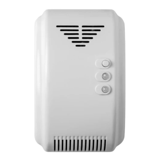
SensoIRIS GAS
!
ATTENTION
The SensoIRIS GAS detector must be
connected only to fire panels, which support
TTE communication protocol!
Operation with SensoIRIS GAS is supported
for the MAIN board firmware revisions:
IRIS - 4.4 and higher; SIMPO - 3.0 and higher!
!
Dimensions
72mm
41mm
!
Installation
IP30
-10°C ÷ +50°C
~108g
Teletek Electronics JSC
Address: 14A Srebarna Str,
1407 Sofia, Bulgaria
General Description
SensoIRIS GAS is a gas detector designed for application in addressable fire alarm
systems, supporting TTE communication protocol.
SensoIRIS GAS is designed for detection of leaking natural gas and LPG. The
detector is equipped with alarm output for management of manipulator
electromagnetic valve (optional accessories).
SensoIRIS GAS is suitable for wall mounting using metal hanger included in the
supplied equipment.
The detector is full programmed from the fire alarm panel - see for details the
programming manuals of IRIS and SIMPO addressable fire alarm panels.
Kit includes:
Gas detector - 1 pc; Hanger - 1 pc; Manual - 1 pc.
Technical Specifications
Operating voltage . . . . . . . . . . . . . . . . . . . . . . . 15-30VDC
Consumption in Standby mode . . . . . . . . . . . . ≤ 80mA @ 24V
Consumption in Alarm mode . . . . . . . . . . . . . . ≤ 100mA @ 24V
Consumption without communication . . . . . . . ≤ 140μA @ 27V
Consumption with communication . . . . . . . . . . ≤ 180μA @ 27V
Warm-up time. . . . . . . . . . . . . . . . . . . . . . . . . . ~180 sec
Alarm level . . . . . . . . . . . . . . . . . . . . . . . . . . . . 10%LEL
Sound level . . . . . . . . . . . . . . . . . . . . . . . . . . . ≥ 85dB
Alarm output. . . . . . . . . . . . . . . . . . . . . . . . . . . 12VDC/ up to 200mA
Relative humidity (no condensation) . . . . . . . . ≤ 95%
Material (plastic). . . . . . . . . . . . . . . . . . . . . . . . ABS
Color . . . . . . . . . . . . . . . . . . . . . . . . . . . . . . . . White
Standard . . . . . . . . . . . . . . . . . . . . . . . . . . . . . GB15322.2-2003
Choosing the Installation Place
Attention: Check if the induced gas is heavier or lighter than air - this is
important when choosing the right place for installation.
Important Note: Avoid installation of the detector close to sources of direct air flow:
vents, fans, air-conditioners, doors, windows, sources of steam, oil vapor, etc.
Ceiling
Detector
0.3 - 1.0m
Distance:
3m
0.3 - 1.0m
Gas source:
Floor
gas oven
Test and Maintenance
Test. To start the test procedure press the test button for more than 3 sec. Apply gas
at distance of 5 cm to the gas convection holes at the bottom of the detector. The red
status LED will start blinking. The detector will resume to normal operation while the
gas density is reduced to level lower than the alarm level.
Note: The frequently testing may result in reducing the sensitivity of the detector.
Maintenance. Clean the gas convection holes every 3 month and test the operation
of the detector.
Installation Instructions
1
Mount the metal holder
on the installation place.
or
Cable
entry
hole
UP
3
Connection diagram of the detector.
P1
External
Power
24 VDC
4
Close the detector cover. Run the
wires through the cable channel
and under the terminal cover.
- The LPG is heavier than
air and the detector should
be placed at height from
the room floor between 0.3
- 1.0m.
- The Natural Gas is lighter
than air and the detector
should be placed at height
from the room ceiling
6
Indication and Operation
between 0.3 - 1.0m.
- The distance from the
detector to the gas source
for the both mentioned
Test button
above cases should not
Power LED
exceed 1.5m.
Status LED
2
Open the detector - undo the
screws on the back, including
these under the terminal cover.
Mounting
holes
!
Attention: Use the description of
the terminals on the PCB only!
Note: Free polarity of the power
input!
-
+
P2
VAL
GND
LOOP
LOOP
+ LOOP (positive wire of the line)
- LOOP (negative wire of the line)
Output for connecting
of solenoid valve
5
Mount the detector to the hanger.
Test button
Press for more than 3 sec to start a test.
Press for 1-2 sec to open the valve (if connected).
Power LED (green)
Blinking for 3 minutes during the initial power up.
Lights on permanently - the detector is in normal operation mode.
Status LED (red/ yellow)
Blinking into red - gas leaking alarm. The internal buzzer is on.
The valve (if connected) will close to shut off the gas pipeline.
Lights on in yellow - detector failure. The internal buzzer is on
with long beeps.
This manual is subject to change without notice!
Cable channel
1
2
Advertisement
Table of Contents

Subscribe to Our Youtube Channel
Related Manuals for Teletek electronics SensoIRIS GAS


Summary of Contents for Teletek electronics SensoIRIS GAS
- Page 1 General Description Installation Instructions English SensoIRIS GAS is a gas detector designed for application in addressable fire alarm systems, supporting TTE communication protocol. Mount the metal holder Open the detector - undo the SensoIRIS GAS is designed for detection of leaking natural gas and LPG. The on the installation place.
- Page 2 üzere tasarlanmıştır. Seçtiğiniz montaj yerine montaj Dedektörü açın – arka kapağın SensoIRIS GAS, metan ve propan - bütan (LPG) gaz kaçaklarını tespit etmek için vidalarını sökün / kapağın altındaki ayağını monte ediniz. tasarlanmıştır. Dedektör, elektromanyetik valf (opsiyonel cihaz) kontrolü için ilave terminal bloğu üstündeki vidaları...
Need help?
Do you have a question about the SensoIRIS GAS and is the answer not in the manual?
Questions and answers