Advertisement
Quick Links
Advertisement

Subscribe to Our Youtube Channel
Related Manuals for versa climber TS


Summary of Contents for versa climber TS
- Page 1 ASSEMBLY MANUAL...
- Page 3 MADE IN USA VersaClimber® and the VersaClimber logo are trademarks or registered trademarks of Heart Rate, Inc. dba VersaClimber in the U.S. and other countries. Publication Date: July, 2019 Country of First Publication: United States of America Author: Heart Rate, Inc. No portion of this guide may be copied, reproduced or distributed other than by written permission of Heart Rate, Inc.
-
Page 5: Table Of Contents
TABLE OF CONTENTS TOOLS REQUIRED ..................... 1 PARTS LIST ......................2 SPECIFICATIONS ....................3 TS PART IDENTIFICATION ................. 4 ASSEMBLY AND INSTALLATION ............... 5 Assembly ....................5-8 MAINTENANCE ....................9 WARRANTY ....................... 10... -
Page 6: Tools Required
TOOLS REQUIRED FOR ASSEMBLY OF A SINGLE TS UNIT: -One Phillips screw driver. -Two 9/16” wrenches. -Two able bodied persons are required for assembly. UNPACKING INSTRUCTIONS The following items are packaged in the container. EQUIPMENT: (single unit TS) Vertical frame/post with control console attached. - Page 7 (2) Base Bolts 3/8” x 3 ¾” long (4) Base Bolts 3/8” x 5/8” long (3) 3/8” lock nuts (3) Side Hand Rail Bolts 3/8” x 4 ¼” long (1) 3” Hand Rail Spacer (3) 3/8” lock nuts (4) Foot Pedal Bolts 3/8” x 1 ½” (1) 3/8”...
-
Page 8: Specifications
TS VERSACLIMBER SPECIFICATIONS PHYSICAL SIZE Height 7 feet, 10 Inches ( 2.1 m 25 cm) Footprint 42 Inches x 45 Inches ( 106 cm x 114 cm) Weight 155 pounds (70 kg) FUNCTIONAL FEATURES Pedal Step Height 0 to 20" (... -
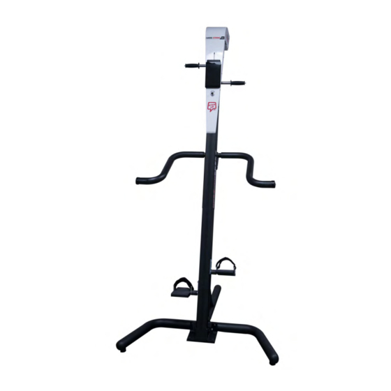
Page 9: Ts Part Identification
TS PART IDENTIFICATION... - Page 10 9/16” wrench, to lock stabilizer in place. Make sure stabilizers are screwed all the way into curved base before assembling TS VersaClimber.
- Page 11 6. Attach the front curved tubular floor brace to the post. Using four hex 9. Lift and hold main post in the vertical head bolts 3/8” x 5/8” long bolts, screw down until firmly tight. upright position. 10. Attach back tubular floor brace to post with (2) hex head bolts 3/8”...
-
Page 12: Assembly
15. Attach foot pedals with “L” shape bracket pointing up, using (2) 3/8” x 1 ½” long hex head bolts. 12. After tubular brace is in place, go back and FULLY TIGHTEN the (2) 3 ¾” long base bolts. 16. Securely TIGHTEN foot pedals. NOTE: It is recommended to visually inspect foot pedals and tighten bolts every (2) months and pedal shaft replacement... - Page 13 18. Insert 3” long spacer and FULLY TIGHTEN all 3 bolts and nuts. Plug the transformer into the back of the post and a 110 volt wall socket. Install quick release handgrips by THE HYDRAULIC SYSTEM depressing pin with thumb and The hydraulic system consists of a heavy duty, reversible inserting into top lug at the upper gear pump.
-
Page 14: Warranty
NOTE: TO MAINTAIN TRAUMA FREE MOTION, IT IS MANDATORY THAT YOU DO NOT, UNDER ANY CIRCUMSTANCES, "BOTTOM OUT" AT THE END OF EACH STROKE. ALSO, DO NOT HIT THE STEP HEIGHT LIMITERS WHEN THEY ARE IN USE. ROLLER AND SLIDE BEARINGS There are rollers and slide bearings made from high pressure application moly-disulfide filled nylon on each oscillating bar. - Page 15 1. Heart Rate Inc. (H.R.I.) warrants to the original purchaser that the TS is free from defects in material and workmanship under normal use and proper maintenance with a three-year limited warranty subject to the terms and conditions hereafter set forth. Except for the above warranty, it is expressly agreed that NO WARRANTY OF MERCHANTABILITY OR FITNESS FOR A PARTICULAR PURPOSE or of a particular use nor any warranty of any kind whatsoever express, implied or statutory is made by H.R.I.
Need help?
Do you have a question about the TS and is the answer not in the manual?
Questions and answers