Table of Contents
Advertisement
Owner's Manual &
Safety Instructions
Model
HE41
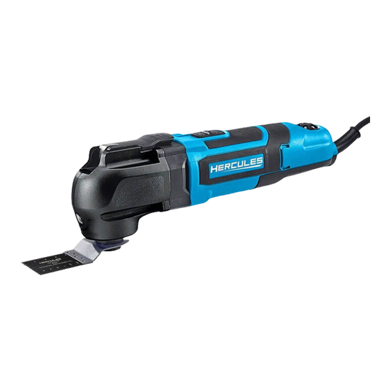
Variable Speed Oscillating Multi-Tool Kit
WARNING: To prevent serious injury, User must read and
understand Owner's Manual. SAVE THIS MANUAL.
When unpacking, make sure that the product is intact and
undamaged. If any parts are missing or broken, please call
1-888-866-5797 as soon as possible. Reference 56214.
Advertisement
Table of Contents

Summary of Contents for Hercules HE41
- Page 1 Owner’s Manual & Safety Instructions Model HE41 Variable Speed Oscillating Multi-Tool Kit WARNING: To prevent serious injury, User must read and understand Owner’s Manual. SAVE THIS MANUAL. When unpacking, make sure that the product is intact and undamaged. If any parts are missing or broken, please call...
-
Page 2: Important Safety Information
IMPORTANT SAFETY INFORMATION GENERAL POWER TOOL SAFETY WARNINGS Personal Safety Read all safety warnings and all instructions. 1. Stay alert, watch what you are doing and use Failure to follow the warnings and instructions may common sense when operating a power tool. Do result in electric shock, fire and/or serious injury. -
Page 3: Vibration Safety
b. When using a handheld power tool, 6. Keep cutting tools sharp and clean. Properly maintain a firm grip on the tool with both maintained cutting tools with sharp cutting edges hands to resist starting torque. are less likely to bind and are easier to control. 7. -
Page 4: Double Insulated Tools: Tools With Two Prong Plugs
Double Insulated Tools: Tools GROUNDING with Two Prong Plugs TO PREVENT ELECTRIC SHOCK AND DEATH FROM INCORRECT GROUNDING: Check with a qualified electrician if you are in doubt as to whether the outlet is properly grounded. Do not modify the power cord plug provided with the tool. -
Page 5: Specifications
Warning Symbols and Definitions TAbLE A: RECOMMENDED MINIMUM WIRE GAUGE FOR EXTENSION CORDS* (120/240 VOLT) This is the safety alert symbol. It is used to EXTENSION CORD NAMEPLATE alert you to potential personal injury hazards. LENGTH AMPERES Obey all safety messages that follow this symbol to 25´... -
Page 6: Tool Set Up
Workpiece and Work Area Set Up OPERATION 1. Designate a work area that is clean and well-lit. Read the ENTIRE IMPORTANT The work area must not allow access by children SAFETY INFORMATION section at the or pets to prevent distraction and injury. beginning of this manual including 2. -
Page 7: Maintenance And Servicing
Cleaning, Maintenance, MAINTENANCE AND SERVICING and Lubrication Procedures not specifically explained 1. bEFORE EACH USE, inspect the general in this manual must be performed condition of the tool. Check for: only by a qualified technician. • loose hardware • misalignment or binding of moving parts •... -
Page 8: Parts List And Diagram
PARTS LIST AND DIAGRAM Parts List Part Description Part Description Release Lever O Ring Middle cover Screw Rotor Set Cylindrical Pin Dust Proof Ring Spanner Base Magnet Ring Hot Board Wind Baffle Ring Spindle Screw Connector Stator Set Compression Spring Trigger Washer Switch Lever... -
Page 9: Assembly Diagram
Assembly Diagram Item 56214 For technical questions, please call 1-888-866-5797. Page 9... - Page 10 Record Product’s Serial Number Here: Note: If product has no serial number, record month and year of purchase instead. Note: Replacement parts are not available. Page 10 For technical questions, please call 1-888-866-5797. Item 56214...
-
Page 11: Limited 90-Day Warranty
LIMITED 90 DAY WARRANTY Harbor Freight Tools Co. makes every effort to assure that its products meet high quality and durability standards, and warrants to the original purchaser that this product is free from defects in materials and workmanship for the period of 90 days from the date of purchase. - Page 12 Visit our website at: http://www.harborfreight.com Email our technical support at: productsupport@harborfreight.com For technical questions, please call 1-888-866-5797 © ® Copyright 2019 by Harbor Freight Tools . All rights reserved. No portion of this manual or any artwork contained herein may be reproduced in any shape or form without the express written consent of Harbor Freight Tools.


Need help?
Do you have a question about the HE41 and is the answer not in the manual?
Questions and answers
My tool came with a extra flange and adapter . What are they for ? Also do the sanding pads come with the tool or do you have to buy them. Its shown in the parts diagram.
The purpose of the extra flange and adapter is to secure and mount different accessories onto the tool’s shaft fitting pins. Sanding pads are not mentioned as being included with the tool.
This answer is automatically generated
What are the 2 extra parts for that came with my Hercules model HE 41 , one looks like a sprocket / disc & one is similar to the flange ?
The two extra parts that come with the Hercules model HE 41 are likely the "Magnet Ring" and the "Spanner Base." The Magnet Ring resembles a sprocket or disc, and the Spanner Base resembles a flange.
This answer is automatically generated