
Related Manuals for HPE FlexNetwork MSR1000


Summary of Contents for HPE FlexNetwork MSR1000
- Page 1 HPE FlexNetwork MSR1000 Routers Installation Guide Part number: 5998-7749R Document version: 6W103-20160205...
- Page 2 © Copyright 2016 Hewlett Packard Enterprise Development LP The information contained herein is subject to change without notice. The only warranties for Hewlett Packard Enterprise products and services are set forth in the express warranty statements accompanying such products and services. Nothing herein should be construed as constituting an additional warranty. Hewlett Packard Enterprise shall not be liable for technical or editorial errors or omissions contained herein.
-
Page 3: Table Of Contents
Contents Preparing for installation ················································································· 1 Safety recommendations ··································································································································· 1 Safety symbols ··········································································································································· 1 General safety recommendations ·············································································································· 1 Electricity safety ········································································································································· 1 Examining the installation site ···························································································································· 2 Temperature and humidity ························································································································· 2 ... - Page 4 Reset button usage guidelines ················································································································· 27 Appendix A Chassis views and technical specifications ······························· 28 Chassis views ·················································································································································· 28 MSR1002-4 ·············································································································································· 28 MSR1003-8 ·············································································································································· 29 MSR1003-8S ············································································································································ 29 Technical specifications ··································································································································· 30 Appendix B LEDs ·························································································· 31 ...
-
Page 5: Preparing For Installation
Preparing for installation The HPE MSR1000 Router Series includes the models in Table Table 1 HPE MSR1000 Router Series models Router model Product code HPE description MSR1002-4 JG875A HPE MSR1002-4 Router BJNGA-BB0034 MSR1003-8 JG732A HPE MSR1003-8 Router BJNGA-BB0029 MSR1003-8S JH060A... -
Page 6: Examining The Installation Site
Examining the installation site The router must be used indoors. To ensure correct operation and long service life of your router, the installation site must meet the following requirements. Temperature and humidity You must maintain a compliant temperature and humidity in the equipment room as described Table •... -
Page 7: Esd Prevention
Figure 1 Airflow through the MSR1000 chassis To ensure good ventilation, the following requirements must be met: • Leave at least 10 cm (3.94 in) of clearance at the air inlet and outlet vents. • The installation site has a good cooling system. ESD prevention CAUTION: Check the resistance of the ESD wrist strap for safety. -
Page 8: Lightning Protection
• A conduction pattern of capacitance coupling. • Inductance coupling. • Electromagnetic wave radiation. • Common impedance (including the grounding system) coupling. To prevent EMI, perform the following tasks: • If AC power is used, use a single-phase three-wire power receptacle with protection earth (PE) to filter interference from the power grid. -
Page 9: Installation Checklist
Installation checklist Table 5 Installation checklist Item Requirements Result • There is a minimum clearance of 10 cm (3.94 in) around the inlet and outlet air vents for heat dissipation of the router chassis. Ventilation • A good ventilation system is available at the installation site. - Page 10 Item Requirements Result • The rack has a good ventilation system. • The rack is sturdy enough to support the weight of the router and installation accessories. Rack-mounting • The size of the rack is appropriate for the requirements router. •...
-
Page 11: Installing The Router
Installing the router WARNING! To avoid injury, do not touch bare wires, terminals, or parts with high-voltage hazard signs. IMPORTANT: • The barcode on the router chassis contains product information that must be provided to local sales agent before you return a faulty router for service. •... - Page 12 Figure 2 Installation flow Start Rack-mounting Workbench-mounting Determine the installation position Mount the router on a Mount the router in a rack workbench Ground the router Install interface modules Connect interface cables Connect the router to a configuration terminal Connect the power cord Verify the installation Power on the router Troubleshoot the router...
-
Page 13: Installing The Router
Installing the router Mounting the router on a workbench IMPORTANT: • Allow 10 cm (3.94 in) of clearance around the chassis for heat dissipation. • Do not place heavy objects on the router. To mount the router on a workbench: Make sure the workbench is clean, stable, and reliably grounded. - Page 14 Figure 5 Marking the positions of cage nuts Insert one edge of a cage nut into the hole. Use a flat-blade screwdriver to compress the other edge of the cage nut, and then push the cage nut fully into the hole. Repeat step 3 to install other cage nuts to all the marked positions on the front rack posts.
- Page 15 Figure 7 Attaching the mounting brackets Place the chassis on the rack and use M6 screws to attach the mounting brackets to the rack posts. Figure 8 Securing the router to the rack...
-
Page 16: Grounding The Router
Grounding the router WARNING! Correctly connecting the router grounding cable is crucial to lightning protection and EMI protection. IMPORTANT: The resistance reading should be smaller than 5 ohms between the chassis and the ground. Grounding the router through the rack IMPORTANT: Make sure the rack is reliably grounded before grounding the router. - Page 17 Figure 9 Grounding the router through the rack (1)
-
Page 18: Grounding The Router With A Grounding Strip
Figure 10 Grounding the router through the rack (2) Grounding the router with a grounding strip If a grounding strip is available at the installation site, connect the grounding cable to the grounding strip. Follow the same procedures in "Grounding the router through the rack"... -
Page 19: Grounding The Router With A Grounding Conductor Buried In The Earth Ground
Figure 11 Grounding the router with a grounding strip Grounding the router with a grounding conductor buried in the earth ground If the installation site has no grounding strips, but earth ground is available, hammer a 0.5 m (1.64 ft) or longer angle iron or steel tube into the earth ground to serve as a grounding conductor. -
Page 20: Installing A Dsic
Figure 12 Removing the filler panel Figure 13 Installing the SIC Installing a DSIC CAUTION: DSICs are not hot swappable. Make sure the router is powered off before installing a DSIC. The MSR1002-4 router does not support DSICs. To install a DSIC: Remove the screws on the filler panel on slot 1 and slot 2 of the router to remove the filler panel, as shown in Figure... -
Page 21: Connecting Interface Cables
Fasten the captive screws to secure the DSIC. Connecting interface cables Connect interface cables before powering on the router. This section describes how to connect Ethernet cables. For other cable connection methods, see HPE MSR Series Routers Interface Module User Guide. To connect an Ethernet cable: Plug one end of an Ethernet cable into the Ethernet port on the router. -
Page 22: Attaching A Usb Device
Figure 17 Connecting the router to a PC Attaching a USB device CAUTION: • Attach only HPE-certified USB devices. • To avoid data loss and hardware damage, do not remove a USB device when it is transmitting data. • The USB port does not support hot-swapping of Sierra Wireless's USB modems. -
Page 23: Setting Terminal Parameters
Figure 19 Connecting the console cable Setting terminal parameters To access the device through the console port, you must run a terminal emulator program (HyperTerminal, PuTTY, or Tera Term) on the configuration terminal. For information about using a terminal emulator program, see the program's user guide. The following are the required terminal settings: •... -
Page 24: Verifying The Installation
Figure 20 Connecting an AC power cord to the router Verifying the installation After you complete the installation, verify that: • There is enough space for heat dissipation around the router, and the rack or workbench is stable. • Interface modules are correctly installed. •... -
Page 25: Observing Boot Information
System is starting... Press Ctrl+D to access BASIC-BOOTWARE MENU... Booting Normal Extended BootWare The Extended BootWare is self-decompressing..Done. **************************************************************************** HPE MSR1003-8S BootWare, Version 2.30 **************************************************************************** Copyright (c) 2010-2015 Hewlett Packard Enterprise Development LP Compiled Date : Sep 11 2014 CPU ID... -
Page 26: Examining The Router After Power-On
Known-answer test for HMAC-SHA1 passed. Known-answer test for HMAC-SHA224 passed. Known-answer test for HMAC-SHA256 passed. Known-answer test for HMAC-SHA384 passed. Known-answer test for HMAC-SHA512 passed. Known-answer test for AES passed. Known-answer test for RSA(signature/verification) passed. Known-answer test for RSA(encrypt/decrypt) passed. Known-answer test for DSA(signature/verification) passed. -
Page 27: Configuring Basic Settings For The Router
After the router is powered on for the first time, configure the basic settings for the router. For information about configuring the MSR1003-8 router, see HPE MSR Routers Fundamentals Configuration Guide (V5) and HPE MSR Routers Fundamentals Command Reference (V5). For information about configuring the MSR1002-4 and MSR1003-8S routers, see HPE MSR Routers Fundamentals Configuration Guide (V7) and HPE MSR Routers Fundamentals Command Reference (V7). -
Page 28: Replacement Procedure
Replacement procedure CAUTION: SICs and DSICs are not hot swappable. Make sure the router is powered off before replacing a SIC or DSIC. Replacing a SIC Loosen the captive screws on the SIC. Gently pull the SIC out along the slide rails. Install a new SIC. - Page 29 Install the filler panels and tighten the screws. Figure 23 Removing a DSIC Figure 24 Installing the slot divider Figure 25 Installing filler panels...
-
Page 30: Troubleshooting
Troubleshooting IMPORTANT: • The barcode on the router chassis contains product information that must be provided to local sales agent before you return a faulty router for service. • Keep the tamper-proof seal on a mounting screw on the chassis cover intact, and if you want to open the chassis, contact Hewlett Packard Enterprise for permission. -
Page 31: No Response From The Serial Port
No response from the serial port If the serial port does not respond, verify that the serial cable is in good condition and the serial port settings are correct. Restoring the factory settings Scenario 1 Symptom When you replace the router, the router password is lost. As a result, you cannot log in to the router and do not know the router configuration. -
Page 32: Appendix A Chassis Views And Technical Specifications
Appendix A Chassis views and technical specifications Chassis views The following figures are for illustration only. MSR1002-4 Figure 26 Front view (1) Power receptacle (2) Gigabit Ethernet port (GE0) (3) Gigabit Ethernet ports (GE1 to GE4) (4) SFP port (SFP5) (5) Asynchronous/synchronous (6) Console port/AUX port (CON/AUX) serial interface (SERIAL0) -
Page 33: Msr1003-8
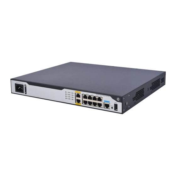
MSR1003-8 Figure 28 Front view (1) Power receptacle (2) Gigabit Ethernet port (GE1) (3) Gigabit Ethernet ports (GE2 to GE8) (4) Console port/AUX port (5) Reset button (RESET) (6) USB port (CON/AUX) (7) Gigabit Ethernet port (GE0) Figure 29 Rear view (1) SIC slot 3 (2) SIC slot 2 (3) SIC slot 1... -
Page 34: Technical Specifications
Figure 31 Rear view (1) SIC slot 3 (2) SIC slot 2 (3) SIC slot 1 (4) Grounding terminal Technical specifications Item MSR1002-4 MSR1003-8 MSR1003-8S Console/AUX port USB port Gigabit Ethernet port SFP port Asynchronous/synchr onous serial interface Memory 1 GB DDR3 1 GB DDR3 1 GB DDR3 Flash... -
Page 35: Appendix B Leds
Appendix B LEDs Panel LEDs Figure 32 MSR1002-4 LEDs (1) Asynchronous/synchronous (2) SFP port LED (SFP5) (3) Power supply LED (PWR) serial interface LED (SERIAL0) (4) System status LED (SYS) (5) 10/100 Mbps link LED for the (6) 1000 Mbps link LED for the Gigabit Ethernet port Gigabit Ethernet port Figure 33 MSR1003-8 LEDs... -
Page 36: Led Description
LED description State Description Comware has started with the configuration file and Flashing green (1 Hz) the router has booted up. Flashing green (8 Hz) The BootWare runs. Steady green The SDRAM is performing self-test. Flashing yellow (1 Hz) The DDR3 SDRAM has failed the self-test. Flashing yellow (8 Hz) The extended segment does not exist. -
Page 37: Appendix C Slot Arrangement
Appendix C Slot arrangement The router provides slots for SICs. A DSIC can be installed if you remove the slot divider between two SIC slots. The slot number of fixed ports on the router is 0. Table 6 Slot arrangement on the router Router Slot arrangement MSR1002-4... -
Page 38: Document Conventions And Icons
Document conventions and icons Conventions This section describes the conventions used in the documentation. Port numbering in examples The port numbers in this document are for illustration only and might be unavailable on your device. Command conventions Convention Description Bold text represents commands and keywords that you enter literally as shown. Boldface Italic text represents arguments that you replace with actual values. -
Page 39: Network Topology Icons
Network topology icons Convention Description Represents a generic network device, such as a router, switch, or firewall. Represents a routing-capable device, such as a router or Layer 3 switch. Represents a generic switch, such as a Layer 2 or Layer 3 switch, or a router that supports Layer 2 forwarding and other Layer 2 features. -
Page 40: Support And Other Resources
Support and other resources Accessing Hewlett Packard Enterprise Support • For live assistance, go to the Contact Hewlett Packard Enterprise Worldwide website: www.hpe.com/assistance • To access documentation and support services, go to the Hewlett Packard Enterprise Support Center website: www.hpe.com/support/hpesc Information to collect •... -
Page 41: Websites
For more information and device support details, go to the following website: www.hpe.com/info/insightremotesupport/docs Documentation feedback Hewlett Packard Enterprise is committed to providing documentation that meets your needs. To help us improve the documentation, send any errors, suggestions, or comments to Documentation Feedback (docsfeedback@hpe.com). When submitting your feedback, include the document title,... - Page 42 part number, edition, and publication date located on the front cover of the document. For online help content, include the product name, product version, help edition, and publication date located on the legal notices page.
-
Page 43: Index
Index grounding the router, lightning protection, power supply failure, connecting power cord, powering on the router, 20, accessories (installation), EMI (site requirements), Appendix A, chassis views and technical specifications, factory settings B, LEDs, restoring, C, slot arrangement, failure (power supply), boot information, garbled terminal display (troubleshooting), grounding... - Page 44 safety symbols, connecting console cable, SIC, 15, connecting router, verifying installation, displaying boot information, interface module grounding router through rack, installing SIC, 15, grounding router with buried grounding conductor, replacing DSIC, grounding router with grounding strip, replacing SIC, grounding the router, SIC installation, 15, installing router in rack, installing router on workbench,...
- Page 45 CF card memory, CF card slot, chassis dimensions, chassis views, CON/AUX port, Gigabit Ethernet port, LED description, LEDs, memory, operating temperature, relative humidity, SIC/DSIC slot, slot arrangement, USB console port, USB port, terminal system configuration problems, troubleshooting garbled display, troubleshooting no display, troubleshooting garbled terminal display, no response from serial port,...
Need help?
Do you have a question about the FlexNetwork MSR1000 and is the answer not in the manual?
Questions and answers