
Related Manuals for HYDAC FILTER SYSTEMS Filtromat OF5 F


Summary of Contents for HYDAC FILTER SYSTEMS Filtromat OF5 F
- Page 1 OF5 F / OF5 L Filtromat Operating and Maintenance Instructions English • (translation of original instructions) Document No. : 3160337i Follow these instructions for proper and safe use. Keep for future reference.
- Page 2 The contact data of the person authorized with the documentation is: Günter Harge c/o HYDAC International GmbH, Industriegebiet, 66280 Sulzbach / Saar Germany Telephone: +49 6897 509 1511 Telefax: +49 6897 509 1394 E-mail: guenter.harge@hydac.com Date of printing: 6/29/2020 © HYDAC FILTER SYSTEMS GmbH 2020 Subject to technical modifications.
-
Page 3: Table Of Contents
HYDAC FILTER SYSTEMS GMBH Table of Contents Table of Contents 1 General ........................ 6 Target group of the manual ................ 6 Illustrations in the manual................ 7 1.2.1 Illustration on the title page .............. 7 1.2.2 Representation of requirements............ 8 1.2.3 Representation of procedural instructions ......... 8 1.2.4... - Page 4 Table of Contents HYDAC FILTER SYSTEMS GMBH 3.7.1 Model code .................. 33 Requirements of the workplace & working environment ...... 34 4 Device description.................... 35 5 Transporting/storing the filter unit................ 37 6 Setting up / assembly / integration of the filter unit .......... 38 Avoiding siphoning .................. 39...
- Page 5 HYDAC FILTER SYSTEMS GMBH Table of Contents 10 Appendix ......................... 64 10.1 EC declaration of conformity ................ 64 10.2 Locating spare parts .................. 64 10.2.1 Order filter elements ................ 66 10.2.1.1 Filter element - Size 330 ............ 66 10.2.1.2 Filter elements - size 1300............ 66 10.3...
-
Page 6: General
1 | General HYDAC FILTER SYSTEMS GMBH 1 General Before you use this product for the first time, read this manual at least up to the chapter "Operation". If you would like to carry out maintenance or troubleshooting, you can find the proce- dure in the respective chapters. -
Page 7: Illustrations In The Manual
HYDAC FILTER SYSTEMS GMBH General | 1 1.2 Illustrations in the manual You will find illustrations in this manual. You can find details re- garding these in the following chapters. 1.2.1 Illustration on the title page You will find the following information on the title page of this... -
Page 8: Representation Of Requirements
1 | General HYDAC FILTER SYSTEMS GMBH Please note that you can directly access information through the directories. However, this does not release you from the obligation to read this manual fully before commissioning. The document no. with the index (4) is meant for identifying and reordering the manual. -
Page 9: Representation Of Intermediate Results/Results
HYDAC FILTER SYSTEMS GMBH General | 1 Procedural instructions with a random sequence Procedural instructions that have a random sequence are listed as bullet points (-). An example of a procedural instruction with a random se- quence: – Clean the display. -
Page 10: Representation Of Warning/General Safety Information
1 | General HYDAC FILTER SYSTEMS GMBH 1.2.5 Representation of warning/general safety information All the warning / general safety information in this manual are highlighted with pictograms and signal words. The pictogram and the signal word give you an indication of the severity of the danger. -
Page 11: Signal Words And Their Meaning In The General Safety Information
HYDAC FILTER SYSTEMS GMBH General | 1 1.2.6 Signal words and their meaning in the general safety information In these instructions you will find the following signal words: DANGER DANGER – The signal word indicates a hazardous situation with a high level of risk, which, if not avoided, will result lethal or serious injury. -
Page 12: Supplementary Symbols
1 | General HYDAC FILTER SYSTEMS GMBH 1.3 Supplementary symbols You will find the following symbols in the manual as additional details: Tip for handling the product Required tools 1.4 Exclusion of liability/warranty For the warranty provided by us, please refer to the Terms of Delivery. -
Page 13: Notes On Copyright
HYDAC FILTER SYSTEMS GMBH General | 1 1.5 Notes on copyright All copyrights for this manual lies with the manufacturer. No part of this manual may be reproduced in any form or pro- cessed, duplicated or distributed using electronic systems with- out the written consent of the manufacturer. -
Page 14: Safety
2 | Safety HYDAC FILTER SYSTEMS GMBH 2 Safety The product is designed as safe. In spite of that, there is dan- ger in some actions that can only be avoided by using the right procedures. These correct procedures and points, which must be followed, are described in this manual. - Page 15 HYDAC FILTER SYSTEMS GMBH Safety | 2 – To train the personnel at regular intervals and to inform them of the hazards – To provide the necessary protective equipment to the per- sonnel Staff who work with the product must be aware of the dangers...
-
Page 16: Tab. 2 Target Group / Required Personnel Qualification
2 | Safety HYDAC FILTER SYSTEMS GMBH Activity Personnel Knowledge Disposal Specialist personnel Knowledge of envi- - General ronmentally friendly disposal of materi- als and matter is re- quired. Knowledge of de- contamination of contaminants is re- quired. Knowledge of recy- cling is required. -
Page 17: Danger Notifications
HYDAC FILTER SYSTEMS GMBH Safety | 2 2.2 Danger notifications The following residual risks can occur in the various life phases: Life phase - Operation The following dangers can occur during the operation life phase: NOTICE Impermissible operating conditions or operating media The filter unit will be damaged. -
Page 18: Observing Regulatory Information
2 | Safety HYDAC FILTER SYSTEMS GMBH NOTICE Switching valve in an intermediate position An intermediate position causes a mixed function u Press the lever of the change over valve up to the limit po- sition. NOTICE Operation without the protective screen The filter unit will be damaged/destroyed u Never operate the filter unit without a protective screen. -
Page 19: Wear Suitable Clothing
HYDAC FILTER SYSTEMS GMBH Safety | 2 2.5 Wear suitable clothing Loose-fitting clothing increases the danger of being caught or being drawn in on rotating parts, and the risk of getting caught on protruding parts. You can be severely injured or killed in these cases. -
Page 20: Fig. 3 Minimum Distance For Fire Fighting
2 | Safety HYDAC FILTER SYSTEMS GMBH Fig. 3: Minimum distance for fire fighting 20 / 84 BeWa OF5F-OF5L 3160337i en-us... -
Page 21: Technical Specifications
HYDAC FILTER SYSTEMS GMBH Technical specifications | 3 3 Technical specifications The OF5 F/L is a filter unit for the offline filtration of hydraulic tanks. In the OF5 S type, it is possible to fill as well as empty a hydraulic tank with an integrated change over valve in addition to the offline filtration. -
Page 22: Proper/Designated Use
3 | Technical specifications HYDAC FILTER SYSTEMS GMBH 3.1 Proper/designated use Use the filter unit only for the application described in the fol- lowing. The filter unit is used in combination with the permitted filter el- ements (identification -KB) to clean / filter hydraulic and lubri- cating oils in the bypass flow or to fill the hydraulic systems, to transfer as well as drain the hydraulic tanks. -
Page 23: Improper Use Or Use Deviating From Intended Use
3.2 Improper use or use deviating from intended use Any use extending beyond this or deviating therefrom shall not be considered intended use. HYDAC FILTER SYSTEMS GMBH will assume no liability for any damage resulting from such use. This risk is borne solely by the owner. -
Page 24: Checking The Scope Of Delivery
3 | Technical specifications HYDAC FILTER SYSTEMS GMBH 3.3 Checking the scope of delivery The filter unit is delivered ready for connection without the filter element installed. Before commissioning the unit, check the contents of the package to make sure everything is present. -
Page 25: Dimensions
HYDAC FILTER SYSTEMS GMBH Technical specifications | 3 3.4 Dimensions Depending on the version, the filter unit has different dimen- sions. You can find details regarding these in the following chapters. 3.4.1 OF5 F/L - Dimensions The OF5 F/L filter unit has the following dimensions. -
Page 26: Hydraulic Diagram
3 | Technical specifications HYDAC FILTER SYSTEMS GMBH 3.5 Hydraulic diagram The hydraulic diagram of the filter unit varies depending on the version. 3.5.1 OF5 F - Hydraulic diagram The OF5 F filter unit has the following hydraulic diagram. Fig. 6: Hydraulic circuit of the OF5 F... - Page 27 HYDAC FILTER SYSTEMS GMBH Technical specifications | 3 14 Differential pressure indicator (op- tional) 17 Air bleed screw on the filter housing BLEED BeWa OF5F-OF5L 3160337i en-us 27 / 84...
-
Page 28: Of5 L - Hydraulic Diagram
3 | Technical specifications HYDAC FILTER SYSTEMS GMBH 3.5.2 OF5 L - Hydraulic diagram The OF5 L filter unit has the following hydraulic diagram. Fig. 7: Hydraulic circuit of the OF5 L 1 Filter housing 3 Drain plug on the filter housing 4 Suction hose with lance and suction... -
Page 29: Technical Data
HYDAC FILTER SYSTEMS GMBH Technical specifications | 3 3.6 Technical Data If you are aware of the technical data of the filter unit, you will be able to use it optimally. The technical data of the filter unit Permitted operating medium Mineral oils and mineral oil- based raffinates. - Page 30 3 | Technical specifications HYDAC FILTER SYSTEMS GMBH Storage duration unlimited Replace all the seals before commissioning after a storage duration of ≥ 2 years. Electrical power consump- OF5x10x3 ≈ 0.75 kW@50Hz tion OF5x10x4 ≈ 1.5 kW@50Hz OF5x10x6 Protection class IP54 Supply voltage See the name plate on the elec- tric motor.
-
Page 31: Decoding The Name Plate
HYDAC FILTER SYSTEMS GMBH Technical specifications | 3 3.7 Decoding the name plate Identification details of the filter unit can be found on the name plates on the filter unit and the components. Always mention the part no. and the serial no. when contacting HYDAC. -
Page 32: Tab. 5 Decoding The Type Label
3 | Technical specifications HYDAC FILTER SYSTEMS GMBH Item Description Pressure max. -> Operating pressure, maximum Weight -> Empty weight Flow rate -> Flow rate Temp. Oil -> Permissible oil temperature range Temp. Amb. -> Permitted ambient temperature range Volume ->... -
Page 33: Model Code
HYDAC FILTER SYSTEMS GMBH Technical specifications | 3 3.7.1 Model code The filter unit is defined by the following model code: OF5 F 10 P 6 N 1 B 05 E / - Basic Type Types = with change over... -
Page 34: Requirements Of The Workplace & Working Environment
3 | Technical specifications HYDAC FILTER SYSTEMS GMBH 3.8 Requirements of the workplace & working environment Requirements of the workplace as well as the working environ- ment can be found in the chapter "Technical data" under: – Permitted ambient temperature range –... -
Page 35: Device Description
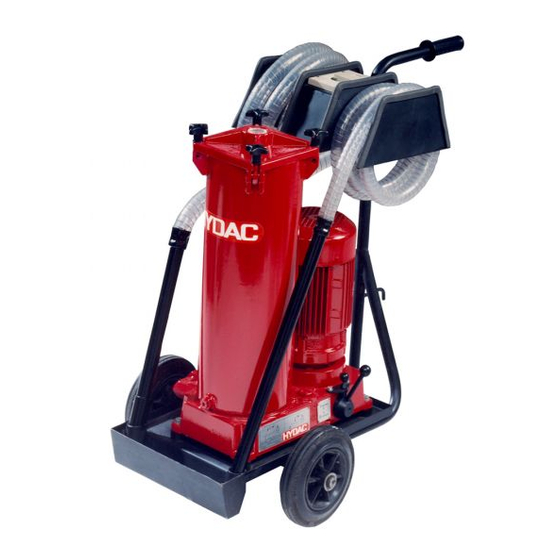
HYDAC FILTER SYSTEMS GMBH Device description | 4 4 Device description The filter unit has the following components/operating ele- ments: Fig. 10: OF5 F/L components / operating elements BeWa OF5F-OF5L 3160337i en-us 35 / 84... - Page 36 4 | Device description HYDAC FILTER SYSTEMS GMBH Item Description Filter housing Filter cover Drain plug on the filter housing DRAIN Suction hose with lance and suction strainer Pressure hose with lance Floor plate with drip tray Dynamic pressure gauge...
-
Page 37: Transporting/Storing The Filter Unit
HYDAC FILTER SYSTEMS GMBH Transporting/storing the filter unit | 5 5 Transporting/storing the filter unit Fully empty the filter unit before transporting it or putting it into storage. Remove the used filter element and dispose of it in an environmentally friendly manner. Clean the inside of the filter housing. -
Page 38: Setting Up / Assembly / Integration Of The Filter Unit
6 | Setting up / assembly / integration of the filter unit HYDAC FILTER SYSTEMS GMBH 6 Setting up / assembly / integration of the filter unit Observe the following notices for mounting the filter unit. – Place the filter unit horizontally on a stable, even and hori- zontal surface. -
Page 39: Avoiding Siphoning
HYDAC FILTER SYSTEMS GMBH Setting up / assembly / integration of the filter unit | 6 6.1 Avoiding siphoning If there is a height difference ΔH between the suction side and pressure side container side / system, the low lying line can develop a suction effect and trigger the siphoning effect be- tween the communicating containers / systems. - Page 40 6 | Setting up / assembly / integration of the filter unit HYDAC FILTER SYSTEMS GMBH After the filter unit is switched off, the height difference/pri- mary pressure can cause flow to occur both in the feed direc- tion and against the feed direction and the fluid can leak un- controllably.
-
Page 41: Measuring Or Displaying The Back Pressure / Differential Pressure
HYDAC FILTER SYSTEMS GMBH Setting up / assembly / integration of the filter unit | 6 6.2 Measuring or displaying the back pressure / differential pressure If pressure measurements are carried out in a hydraulic sys- tem, the type of measurement such as the back pressure or differential pressure and also the measurement point are cru- cial, as shown below. -
Page 42: Avoiding The Mixing Of Oils - Emptying The Filter Unit
6 | Setting up / assembly / integration of the filter unit HYDAC FILTER SYSTEMS GMBH 6.3 Avoiding the mixing of oils - Emptying the filter unit If you want to use the same oil for operation as in the previous operation, it is not serious if the oils are mixed. -
Page 43: Making The Electrical Connections
HYDAC FILTER SYSTEMS GMBH Setting up / assembly / integration of the filter unit | 6 6.4 Making the electrical connections Depending on the version, the filter unit has different drive mo- tors (different voltage / output / number of phases, etc.). Follow the instructions in the next section to electrically connect the fil- ter unit. -
Page 44: Connecting The Filter Unit With A Three-Phase Electric Motor
6 | Setting up / assembly / integration of the filter unit HYDAC FILTER SYSTEMS GMBH 6.4.2 Connecting the filter unit with a three-phase electric motor The filter unit is equipped with a three-phase electric motor, on/ off switch, motor protection and connection plug; connect the filter unit in accordance with the following steps. -
Page 45: Connecting The Suction/Pressure Port
HYDAC FILTER SYSTEMS GMBH Setting up / assembly / integration of the filter unit | 6 6.5 Connecting the suction/pressure port Take into account the pressure loss when connecting suction/ pressure hoses. The suction / pressure hoses from the filter unit Accessories list are matched to the filter unit. - Page 46 6 | Setting up / assembly / integration of the filter unit HYDAC FILTER SYSTEMS GMBH – Note that the nominal size of the connected hose/piping must correspond to the cross-section of the connection thread. – Make sure that the connection hoses/piping (suction side/ pressure side) do not cause any tension or vibrations to be carried over to the filter unit.
-
Page 47: Attaching / Connecting The Suction / Pressure Hoses (Accessories)
HYDAC FILTER SYSTEMS GMBH Setting up / assembly / integration of the filter unit | 6 6.6 Attaching / connecting the suction / pressure hoses (Accessories) Take into account the pressure loss when connecting suction/ pressure hoses. The suction/pressure hoses from the filter unit Accessories list are matched to the filter unit. -
Page 48: Inserting The Filter Element
6 | Setting up / assembly / integration of the filter unit HYDAC FILTER SYSTEMS GMBH 6.7 Inserting the filter element The filter unit has no filter element installed upon delivery from the factory. Before commissioning check whether a filter ele- ment is present in the filter housing. -
Page 49: Operation
HYDAC FILTER SYSTEMS GMBH Operation | 7 7 Operation Different operating modes are available depending on the ver- sion (see the model code) of the filter unit. The filter unit is equipped with a clogging indicator (differential pressure indicator or clogging indicator) to monitor the service life of the filter element. -
Page 50: Activating The Main Switch
7 | Operation HYDAC FILTER SYSTEMS GMBH 7.1 Activating the main switch Depending on the version with a visual or electrical clogging in- dicator, the main switch differs according to the following fig- ure: Fig. 15: Activate the main switch L Main switch / E-STOP... -
Page 51: Of5L - Operating Mode
HYDAC FILTER SYSTEMS GMBH Operation | 7 7.2 OF5L – Operating mode The OF5L filter unit cannot change over between the operating modes. This filter unit can only be operated in the operation mode - Transfer with filtration. Fig. 16: OF5L - Operating mode Transfer and filter... -
Page 52: Of5S - Selecting Operating Modes
7 | Operation HYDAC FILTER SYSTEMS GMBH 7.3 OF5S - Selecting operating modes The filter unit OF5F has two change over valves for changing over the operating mode. You will find details for operation in the subsequent chapters. 7.3.1 Operating the change over valve Select the desired operating mode via the change over valve. -
Page 53: Fig. 18 External Change Over Valve
HYDAC FILTER SYSTEMS GMBH Operation | 7 Fig. 18: External change over valve BeWa OF5F-OF5L 3160337i en-us 53 / 84... -
Page 54: Operating Mode - Transfer Without Filtration A -> B
7 | Operation HYDAC FILTER SYSTEMS GMBH 7.3.2 Operating mode - Transfer without filtration A -> B For the operating mode - Transfer without filtration, adjust both the change over valves as described in the following. The fluid is pumped from the connection A to connection B. For details see figure. -
Page 55: Operating Mode - Transfer With Filtration B -> T
HYDAC FILTER SYSTEMS GMBH Operation | 7 7.3.3 Operating mode - Transfer with filtration B -> T For the operating mode - Transfer with filtration, adjust both the change over valves as described in the following. The fluid will be pumped from connection A to connection T. For details see figure. -
Page 56: Observing The Optical Clogging Indicator (Optional)
7 | Operation HYDAC FILTER SYSTEMS GMBH 7.4 Observing the optical clogging indicator (optional) If the filter unit / filter housing is equipped with an optical clog- ging indicator, then check it daily. Change the filter element at a permissible differential pressure across the filter element or once the clogging indicator enters the red zone. - Page 57 HYDAC FILTER SYSTEMS GMBH Performing maintenance | 8 8 Performing maintenance For a long, trouble-free service life of the filter unit, regular maintenance activities are required. In this chapter, you will find the description of the required maintenance activities and the qualifications of the staff needed to carry out these tasks.
-
Page 58: Performing Maintenance
8 | Performing maintenance HYDAC FILTER SYSTEMS GMBH 8.2 Changing the filter element Procedure for changing the filter element. is given in this chap- 1x Allen wrench = 5 mm Suitable receiver bin for collecting the oil from the filter housing. ü... - Page 59 HYDAC FILTER SYSTEMS GMBH Performing maintenance | 8 5. Lift the filter cover up and remove the filter element. Dispose the filter element in an environmentally safe manner. 6. Clean the - inside of the filter bowl of any course dirt - the sealing surfaces on the filter bowl and filter cover.
- Page 60 8 | Performing maintenance HYDAC FILTER SYSTEMS GMBH 10. Fit the filter cover. NOTICE! Pay attention to the O-ring in filter cover while doing so. It must not be damaged. 11. Fold the four star gripped screws upwards and turn the star gripped nuts clockwise, screw them crosswise uni- formly.
-
Page 61: Cleaning The Protective Screen
HYDAC FILTER SYSTEMS GMBH Performing maintenance | 8 8.3 Cleaning the protective screen To protect the pump from coarse contaminant particles or for- eign bodies, a protective screen is installed in the suction lance. Clean the strainer regularly. Check the protective screen immediately in the event of insufficient suction or delivery rate. - Page 62 8 | Performing maintenance HYDAC FILTER SYSTEMS GMBH 2. Remove the protective screen (4) from the protection pipe. 3. Clean the protective screen (4) by washing it out and then blowing it out with compressed air. 4. Insert the protective screen (4) into the protection pipe (5) with the tip facing forwards.
-
Page 63: Decommissioning / Disposal
HYDAC FILTER SYSTEMS GMBH Decommissioning / Disposal | 9 9 Decommissioning / Disposal In the following chapters, you will be provided with information regarding temporary shutdown/final decommissioning and dis- posal of the product. 9.1 Temporary shutdown If the product is being temporarily shut down, the following... -
Page 64: Appendix
10 | Appendix HYDAC FILTER SYSTEMS GMBH 10 Appendix In this annex, you will find supplementary information on the product. 10.1 EC declaration of conformity The CE declaration of conformity can be found in the Technical Documentation that is part of the scope of delivery for the product. -
Page 65: Tab. 7 Spare Parts List Of5
HYDAC FILTER SYSTEMS GMBH Appendix | 10 Description Part no. Differential pressure indicator FKM 316556 Tab. 7: Spare parts list OF5… *) available on request Description Part no. Pressure hose with lance, length = NW25 381465 3 m Pressure hose with lance, length =... -
Page 66: Order Filter Elements
10 | Appendix HYDAC FILTER SYSTEMS GMBH 10.2.1 Order filter elements Select the filter element depending on size of your filter unit. The following includes filter elements as per size, filtration rat- ing and seal material. 10.2.1.1 Filter element - Size 330... -
Page 67: Tab. 10 Filter Elements - Size 1300
HYDAC FILTER SYSTEMS GMBH Appendix | 10 Description Part no. Filter element 10 µm 1300 R 010 ON/-V- FPM 1263762 Filter element 20 µm 1300 R 020 ON/-KB NBR 1263062 Filter element 20 µm 1300 R 020 ON/-V- FPM 1263763 Filter element 40 µm 1300 R 040 AM/-KB NBR 1267699 Tab. 10: Filter elements - size 1300... -
Page 68: Clogging Indicators - Technical Data
10 | Appendix HYDAC FILTER SYSTEMS GMBH 10.3 Clogging indicators - technical data Listed below are the technical data pertaining to the optional, optical or electrical clogging indicators suitable for the installa- tion in the filter housing / filter unit. -
Page 69: Tab. 11: Differential Pressure Indicator -Visual Vm X B.x
HYDAC FILTER SYSTEMS GMBH Appendix | 10 Permissible operating over- ≤ 210 bar pressure Permitted temperature range -30 … +100°C Connector threads G ½ Installation space required According to HN 28-22 Maximum tightening torque 33 Nm Tab. 11: Differential pressure indicator -visual VM x B.x BeWa OF5F-OF5L 3160337i en-us 69 / 84... -
Page 70: Differential Pressure Indicator, Visual - Vm X Bm.x
10 | Appendix HYDAC FILTER SYSTEMS GMBH 10.3.2 Differential pressure indicator, visual – VM x BM.x The optical differential pressure gauge reacts to the increasing pressure difference at the increasing contamination level of the filter element. Fig. 27: Differential pressure gauge, visual VM x BM.x... -
Page 71: Tab. 12: Differential Pressure Indicator, Visual Vm X Bm.x
HYDAC FILTER SYSTEMS GMBH Appendix | 10 Permissible operating over- ≤ 210 bar pressure Permitted temperature range -30 … +100°C Connector threads G ½ Installation space required According to HN 28-22 Tab. 12: Differential pressure indicator, visual VM x BM.x BeWa OF5F-OF5L 3160337i en-us 71 / 84... -
Page 72: Differential Pressure Gauge, Electric (Vm X C.x)
10 | Appendix HYDAC FILTER SYSTEMS GMBH 10.3.3 Differential pressure gauge, electric (VM x C.x) The electric clogging indicator reacts to the increasing pres- sure difference at the increasing contamination level of the fil- ter element. Fig. 28: Differential pressure indicator, electrical VM x C.x... -
Page 73: Tab. 13: Differential Pressure Indicator, Electrical Vm X C.x
HYDAC FILTER SYSTEMS GMBH Appendix | 10 Response pressure and indi- VM 2 C.x = 2 bar -10% cation range respectively VM 3 C.x = 3 bar -10% VM 5 C.x = 5 bar -10% Permissible operating over- ≤ 210 bar pressure Permitted temperature range -30 … +100°C Connector threads G ½ Installation space required According to HN 28-22 Maximum tightening torque 33 Nm... -
Page 74: Differential Pressure Gauge, Electric (Vm X D.x /-L-Xx)
10 | Appendix HYDAC FILTER SYSTEMS GMBH 10.3.4 Differential pressure gauge, electric (VM x D.x /-L- The electric clogging indicator reacts to the increasing pres- sure difference at the increasing contamination level of the fil- ter element. Fig. 29: Differential pressure indicator, electrical VM x D.x /-Lxx... -
Page 75: Tab. 14 Differential Pressure Indicator, Electrical Vm X D.x / -Lxx
HYDAC FILTER SYSTEMS GMBH Appendix | 10 Response pressure and indi- VM 2 D.x = 2 bar -10% cation range respectively VM 3 D.x = 3 bar -10% VM 5 D.x = 5 bar -10% Permissible operating over- ≤ 210 bar pressure Permitted temperature range -30 … +100°C Connector threads G ½ Installation space required According to HN 28-22 Maximum tightening torque 33 Nm... -
Page 76: Contacting Customer Service
10 | Appendix HYDAC FILTER SYSTEMS GMBH 10.4 Contacting Customer Service Contact data such as the telephone numbers, e-mail and mail- ing addresses for the Hotline, product support, , , service part- ners for maintenance, repair and spare parts can be found, al- ways updated, on our homepagewww.hydac.com. - Page 77 HYDAC FILTER SYSTEMS GMBH Table of Illustrations Table of Illustrations Overview / labeling of the title page ............Fig. 1 Fire protection class B ................Fig. 2 Minimum distance for fire fighting............. Fig. 3 Checking the scope of delivery ..............
- Page 78 Table of Illustrations HYDAC FILTER SYSTEMS GMBH Observe the optical clogging indicator ............. Fig. 25 Differential pressure indicator - visual VM x B.x ........Fig. 26 Differential pressure gauge, visual VM x BM.x......... Fig. 27 Differential pressure indicator, electrical VM x C.x ........Fig. 28 Differential pressure indicator, electrical VM x D.x /-Lxx ......
- Page 79 HYDAC FILTER SYSTEMS GMBH Index of Tables Index of Tables Tab. 1 Target group ..................... Tab. 2 Target group / Required personnel qualification ........Tab. 3 Checking the scope of delivery ..............Tab. 4 Technical data ..................Tab. 5 Decoding the type label ................
-
Page 80: Glossary
Glossary HYDAC FILTER SYSTEMS GMBH Glossary General Terms and Conditions Operating personnel - General The General Terms and Conditions Such persons have been instructed are available at our home page about the handling and operation of www.hydac.com ⇨ General Terms the product and informed about po- and Conditions. - Page 81 HYDAC FILTER SYSTEMS GMBH Glossary Specialist personnel - Mechanical Such persons have specific special- ist training and several years' work experience. They are able to as- sess and perform the work as- signed to them, they are also able to recognize potential dangers.
-
Page 82: Index
Index HYDAC FILTER SYSTEMS GMBH Index Back pressure vs. Differential pressure filter element 41 change 58 Branches 76 commission 66 calculating pressure loss 45 Hotline 76 CE declaration of conformity 24, 64 HYDAC Service Clogging indicator Germany 76 Differential pressure indicator Worldwide 76... - Page 83 HYDAC FILTER SYSTEMS GMBH Index transfer with filtration B -> T 55 transfer without filtration A -> B 54 operation mode Transfer with filtration 51 Person authorized with the documenta- tion 2 power plug exchange 43 IP protection class 43 protective screen clean 61 publisher 2...
- Page 84 www.hydac.com...
Need help?
Do you have a question about the Filtromat OF5 F and is the answer not in the manual?
Questions and answers