Sign In
Upload
Manuals
Brands
HYDAC FILTER SYSTEMS Manuals
Industrial Equipment
Filtromat OF5 F
HYDAC FILTER SYSTEMS Filtromat OF5 F Unit Manuals
Manuals and User Guides for HYDAC FILTER SYSTEMS Filtromat OF5 F Unit. We have
1
HYDAC FILTER SYSTEMS Filtromat OF5 F Unit manual available for free PDF download: Operating And Maintenance Instructions Manual
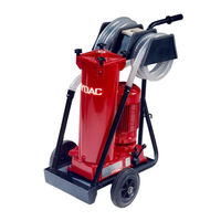
HYDAC FILTER SYSTEMS Filtromat OF5 F Operating And Maintenance Instructions Manual (84 pages)
Brand:
HYDAC FILTER SYSTEMS
| Category:
Industrial Equipment
| Size: 4 MB
Table of Contents
Table of Contents
3
1 General
6
Target Group of the Manual
6
Tab. 1 Target Group
6
Illustrations in the Manual
7
Illustration on the Title Page
7
Fig. 1 Overview / Labeling of the Title Page
7
Representation of Procedural Instructions
8
Representation of Requirements
8
Representation of Intermediate Results/Results
9
Representation of Warning/General Safety Information
10
Signal Words and Their Meaning in the General Safety Information
11
Supplementary Symbols
12
Exclusion of Liability/Warranty
12
Notes on Copyright
13
Validity of this Manual
13
2 Safety
14
Target Group/Required Personnel Qualification
14
Tab. 2 Target Group / Required Personnel Qualification
16
Danger Notifications
17
Observing Regulatory Information
18
Ensuring Environmental Protection
18
Wear Suitable Clothing
19
Stoppage in an Emergency (EMERGENCY STOP)
19
Fire-Fighting / Extinguishing a Fire
19
Fig. 2 Fire Protection Class B
19
Fig. 3 Minimum Distance for Fire Fighting
20
3 Technical Specifications
21
Proper/Designated Use
22
Improper Use or Use Deviating from Intended Use
23
Checking the Scope of Delivery
24
Fig. 4 Checking the Scope of Delivery
24
Tab. 3 Checking the Scope of Delivery
24
Dimensions
25
OF5 F/L - Dimensions
25
Fig. 5 3389483_Dimensions_01
25
Hydraulic Diagram
26
OF5 F - Hydraulic Diagram
26
Fig. 6 Hydraulic Circuit of the OF5 F
26
OF5 L - Hydraulic Diagram
28
Fig. 7 Hydraulic Circuit of the OF5 L
28
Technical Data
29
Decoding the Name Plate
31
Fig. 8 Decoding the Type Label
31
Tab. 5 Decoding the Type Label
32
Model Code
33
Fig. 9 Model Code OF5 F/L
33
Requirements of the Workplace & Working Environment
34
4 Device Description
35
Fig. 10 OF5 F/L Components / Operating Elements
35
5 Transporting/Storing the Filter Unit
37
Fig. 11 Transporting the OF5 F/L
37
Tab. 4 Technical Data
37
6 Setting up / Assembly / Integration of the Filter Unit
38
Avoiding Siphoning
39
Fig. 12 Avoiding Siphoning
39
Measuring or Displaying the Back Pressure / Differential Pressure
41
Fig. 13 Measure or Display Dynamic Pressure / Differential Pressure
41
Avoiding the Mixing of Oils - Emptying the Filter Unit
42
Making the Electrical Connections
43
Connecting the Filter Unit with 1 Phase Electric Motor
43
Connecting the Filter Unit with a Three-Phase Electric Motor
44
Connecting the Suction/Pressure Port
45
Fig. 14 Pressure Loss Formula
45
Attaching / Connecting the Suction / Pressure Hoses (Accessories)
47
Inserting the Filter Element
48
Commissioning
48
7 Operation
49
Activating the Main Switch
50
Fig. 15 Activate the Main Switch
50
OF5L - Operating Mode
51
Fig. 16 OF5L - Operating Mode Transfer and Filter
51
OF5S - Selecting Operating Modes
52
Operating the Change over Valve
52
Fig. 17 Internal Change over Valve
52
Fig. 18 External Change over Valve
53
Operating Mode - Transfer Without Filtration a -> B
54
Fig. 19 Operating Mode - Transfer Without Filtration a -> B
54
Fig. 20 Internal Change over Valve - Position I
54
Fig. 21 External Change over Valve - Position I
54
Operating Mode - Transfer with Filtration B -> T
55
Fig. 22 Operating Modes - Transfer with Filtration B -> T
55
Fig. 23: Internal Change over Valve - Position II
55
Fig. 24: External Change over Valve - Position II
55
Observing the Optical Clogging Indicator (Optional)
56
Fig. 25 Observe the Optical Clogging Indicator
56
8 Performing Maintenance
58
Changing the Filter Element
58
Cleaning the Protective Screen
61
Tab. 6 Suction Lance with Protective Screen
61
9 Decommissioning / Disposal
63
Temporary Shutdown
63
Final Decommissioning
63
Disposal
63
10 Appendix
64
EC Declaration of Conformity
64
Locating Spare Parts
64
Tab. 7 Spare Parts List OF5
65
Tab. 8 Spare Parts List for the OF5F/OF5L
65
Filter Element - Size 330
66
Filter Elements - Size 1300
66
Order Filter Elements
66
Tab. 10 Filter Elements - Size 1300
67
Clogging Indicators - Technical Data
68
Differential Pressure Indicator, Visual - VM X B.X
68
Fig. 26: Differential Pressure Indicator - Visual VM X B.X
68
Tab. 11: Differential Pressure Indicator -Visual VM X B.X
69
Differential Pressure Indicator, Visual - VM X Bm.X
70
Fig. 27: Differential Pressure Gauge, Visual VM X Bm.X
70
Tab. 12: Differential Pressure Indicator, Visual VM X Bm.X
71
Differential Pressure Gauge, Electric (VM X C.X)
72
Fig. 28: Differential Pressure Indicator, Electrical VM X C.X
72
Tab. 13: Differential Pressure Indicator, Electrical VM X C.X
73
Differential Pressure Gauge, Electric (VM X D.X /-L-XX)
74
Fig. 29 Differential Pressure Indicator, Electrical VM X D.X /-Lxx
74
Tab. 14 Differential Pressure Indicator, Electrical VM X D.X / -Lxx
75
Contacting Customer Service
76
Tab. 15 HYDAC Service Deutschland
76
Table of Illustrations
77
Glossary
80
Index
82
Advertisement
Advertisement
Related Products
HYDAC FILTER SYSTEMS Filtromat OF5 L
HYDAC FILTER SYSTEMS OFU-ATEX
HYDAC FILTER SYSTEMS OFU-10-P-2-N-2-B-05-B/-
HYDAC FILTER SYSTEMS OXiStop OXS
HYDAC FILTER SYSTEMS OXiStop OXS 30
HYDAC FILTER SYSTEMS OXiStop OXS 45
HYDAC FILTER SYSTEMS OXiStop OXS 70
HYDAC FILTER SYSTEMS OXS-30-N-1-Z-Z-2-2-ACD-/-
HYDAC FILTER SYSTEMS OFU Filtromat
HYDAC FILTER SYSTEMS OF7
HYDAC FILTER SYSTEMS Categories
Water Filtration Systems
Control Unit
Industrial Equipment
Measuring Instruments
Test Equipment
More HYDAC FILTER SYSTEMS Manuals
Login
Sign In
OR
Sign in with Facebook
Sign in with Google
Upload manual
Upload from disk
Upload from URL