
Related Manuals for HYDAC FILTER SYSTEMS FluidAqua Mobil FAM 5


Summary of Contents for HYDAC FILTER SYSTEMS FluidAqua Mobil FAM 5
- Page 1 FAM 5 FluidAqua Mobil Operating and Maintenance Instructions English (translation of original operating instructions) Documentation no.: 3667663b...
-
Page 2: Imprint
++49 (0)6897 509 1394 E-Mail: guenter.harge@hydac.com © HYDAC FILTER SYSTEMS GMBH All rights reserved. No part of this work may be reproduced in any form (print, photocopy or by other means) or processed, duplicated or distributed using electronic systems without the written consent of the publisher. -
Page 3: Table Of Contents
Content Content Imprint......................2 Documentation Representative ..............2 Content ......................3 Preface......................6 Technical Support..................7 Modifications to the Product ................7 Warranty ......................7 Using the documentation ................8 Safety information ..................9 Hazard symbols ...................9 Signal words and their meaning in the safety information and instructions ....................10 Structure of the safety information and instructions........11 Observe regulatory information ..............11 Proper/Designated Use ................12... - Page 4 Content Hydraulic diagram..................29 Working principle of FAM ................31 Possible applications .................32 Bypass purification .................32 Transfer by pumping ................32 FAM Set-up and Connection ..............33 Setting up the FAM ..................33 Notes on pipes and hoses .................35 Connecting the inlet (IN).................37 Connect outlet (OUT) ................38 Preparing the Vacuum Pump..............38 Check air outlet of the vacuum pump .............39 Electrical connection of the FAM ...............40...
- Page 5 Content Changing the oil of the vacuum pump ............73 Replacing the air de-oiling element of the vacuum pump.......74 Clean the suction strainer................75 Replacing the filter element on the fluid filter ..........76 Heater maintenance (optional) ..............81 Inspecting/Cleaning the heating element ..........81 Removing/Installing the heating element ..........82 Resetting the safety thermostat..............84 Checking the AquaSensor AS1000 ............86...
-
Page 6: Preface
If you discover errors while reading the documentation or have suggestions or other useful information, please don’t hesitate to contact us: HYDAC FILTER SYSTEMS GMBH Technische Dokumentation Postfach 12 51... -
Page 7: Technical Support
Warranty For the warranty provided by us, please refer to the General Terms of Sale and Delivery of HYDAC Filter Systems GmbH. You will find these under www.hydac.com -> General terms and conditions. FAM 5... -
Page 8: Using The Documentation
Preface Using the documentation Note that the method described for locating specific information does not release you from your responsibility of carefully reading these instructions prior to starting the unit up for the first time and at regular intervals in the future. WHAT do I want to know? I determine which topic I am looking for. -
Page 9: Safety Information
Safety information Safety information The unit was built according to the statutory provisions valid at the time of delivery and satisfies current safety requirements. Any residual hazards are indicated by safety information and instructions and are described in the operating instructions. Observe all safety and warning instructions attached to the unit. -
Page 10: Signal Words And Their Meaning In The Safety Information And Instructions
Safety information Risk of burns due to hot surfaces Substances that are health hazards or irritants Danger from explosive atmosphere Signal words and their meaning in the safety information and instructions DANGER DANGER indicates a danger with a high risk and which will lead to death or serious injury if not avoided. -
Page 11: Structure Of The Safety Information And Instructions
Safety information Structure of the safety information and instructions All warning instructions in this manual are highlighted with pictograms and signal words. The pictogram and the signal word indicate the severity of the danger. Warning instructions listed before an activity are laid out as follows: SIGNAL WORD Type and source of danger HAZARD SYMBOL... -
Page 12: Proper/Designated Use
Safety information Proper/Designated Use Use the unit only for the application described in the following. The FAM is for dewatering, filtering and degassing hydraulic and lubricating oils. In addition, it removes free water, emulsified water and a large percentage of the water found in solution. Proper or designated use of the product extends to the following: ... - Page 13 ► media. Any use extending beyond or deviating therefrom shall not be considered intended use. HYDAC Filter Systems GmbH will assume no liability for any damage resulting from such use. The user alone, shall assume any and all associated risk Improper use may result in hazards and/or will damage the unit.
-
Page 14: Qualifications Of Personnel / Target Group
Safety information Qualifications of personnel / target group Persons who work on the power unit must be aware of the associated hazards when using the power unit. Operating and specialist personnel must have read and understood the operating instructions, in particular the safety information and instructions, and applicable regulations before beginning work. - Page 15 Safety information Knowledge about reuse FAM 5 en(us) 15 / 100 BEWA FAM5 3667663b en-us 2012-12-12.doc 2012-12-12...
-
Page 16: Wear Suitable Clothing
Unpacking the FAM Wear suitable clothing Loosely worn clothing increases the danger of getting caught or wound up in rotating parts and the danger of getting snagged on projecting parts. You can be severely injured or killed. Wear close-fitting clothing. ... -
Page 17: Transporting The Fam
Transporting the FAM Transporting the FAM NOTICE Using components for pushing / pulling The FAM will be damaged Never use the components to push or pull the FAM. ► Use the grips provided for shifting. ► Wind the suction and pressure hose and the connection cable around the holders provided for this purpose and either fasten them in place or remove the hoses from the FAM. -
Page 18: Horizontal Transport
Transporting the FAM Horizontal transport Completely empty the FAM as well as the vacuum pump before truck transport, and close off all connections. Close the air outlet of the vacuum pump using the matching suitable screw plugs. Ensure the FAM is fixed tight to the car using load restraint belts at the suitable lashing points in the car. -
Page 19: Vertical Transport
Transporting the FAM Vertical transport For transport by rail or truck, supports must be placed under the mobile FAM so that none of the rollers are subjected to load pressure. Secure the FAM with suitable belts. Stationary version Mobile version FAM 5 en(us) 19 / 100... -
Page 20: Transport Suspended On A Crane
Transporting the FAM Transport suspended on a crane NOTICE Unsuitable lifting accessories The unit/components will be damaged/destroyed Use only suitable lifting accessories to raise or lash the FAM. ► Make sure that the lifting accessories do not cause any force to be ►... -
Page 21: Checking The Scope Of Delivery
Checking the scope of delivery Checking the scope of delivery Upon receiving the FAM check it for any damage in transit. Immediately report any damage in transit to the forwarding agent or the HYDAC department in charge. The following items are included in the scope of delivery: Qty. -
Page 22: Fam Description
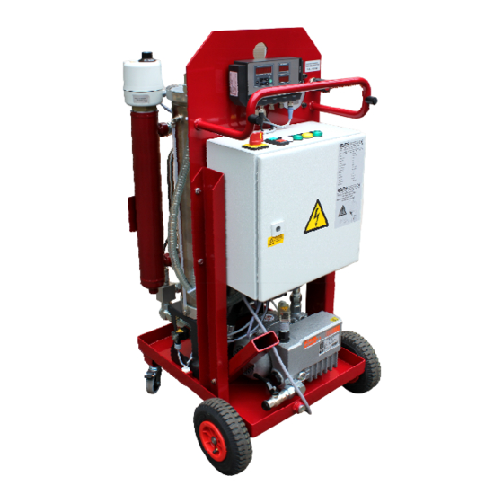
FAM Description FAM Description The FluidAqua FAM was developed for the dewatering, filtration and degassing of hydraulic and lubricating oils. It removes free water, emulsified water and a large percentage of the water to be found in solution. The integrated fluid filter ensures an efficient separation of solid particles. Degassing of the medium is also achieved via the vacuum installed in the vacuum chamber. -
Page 23: Fam Features
FAM Description FAM features The FAM is able to reduce fluids described in the chapter "Suitable fluids" typically to the following attainable Residual water contents: Hydraulic and lubrication oils < 100ppm Turbine oil (ISO VG32/46) < 50 ppm Transformer oil <... - Page 24 FAM Description As an approximate guideline, the dimensioning of the FluidAqua Mobil can be defined in accordance with the tank volume. Tank volume in liters Size < 1,500 FAM 5 1,000 … 7,000 FAM 10, FAM 10/15 7,000 … 15,000 FAM 25 15,000 …...
-
Page 25: Fam System Components
FAM Description FAM system components FAM 5 en(us) 25 / 100 BEWA FAM5 3667663b en-us 2012-12-12.doc 2012-12-12... - Page 26 FAM Description Item Designation Oil pan 2.21 Pneumatic tire (mobile version only) 2.30 Swivel caster (mobile version only) Vacuum column 3.68 Vacuum gauge (underpressure setting in the vacuum column) 3.73 Air Filter 3.85 3/2 directional valve Motor pump assembly ContaminationSensor CS (Optional) Fluid filter for separating solid particles OLF5...
-
Page 27: Dimensions - Stationary Unit
Dimensions – stationary unit Dimensions – stationary unit FAM 5 en(us) 27 / 100 BEWA FAM5 3667663b en-us 2012-12-12.doc 2012-12-12... -
Page 28: Dimensions - Mobile Unit
Dimensions – mobile unit Dimensions – mobile unit FAM 5 en(us) 28 / 100 BEWA FAM5 3667663b en-us 2012-12-12.doc 2012-12-12... -
Page 29: Hydraulic Diagram
Hydraulic diagram Hydraulic diagram FAM 5 en(us) 29 / 100 BEWA FAM5 3667663b en-us 2012-12-12.doc 2012-12-12... - Page 30 Hydraulic diagram Item Designation Oil pan 1.04 Float switch in oil pan Vacuum column 3.37 Vacuum pressure gauge 3.38 Level switch in the vacuum column 3.43 Fluid level indication of the vacuum column Vacuum gauge 3.68 (underpressure setting in the vacuum column) 3.73 Air Filter 3.85...
-
Page 31: Working Principle Of Fam
Working principle of FAM Working principle of FAM After you switch on the FAM, the motor pump assembly (4.0), depending on the fill level in the vacuum column, starts to suck either from the vacuum column or the tank via the suction strainer (4.02) or from the vacuum column and the 3/2 directional valve (3.85). -
Page 32: Possible Applications
Working principle of FAM Possible applications Bypass purification Attach the FAM to the tank which is to be cleaned by means of a suction and pressure line and switch it on. The permanent bypass purification means you always get optimum purity results. Transfer by pumping Connect up the FAM to a contaminated oil tank by means of a suction line and pump the fluid into the clean oil tank via the FAM. -
Page 33: Fam Set-Up And Connection
FAM Set-up and Connection FAM Set-up and Connection Setting up the FAM CAUTION Danger of tipping on inclines Crushing hazard Operate the power unit only on an even, level ► surface. Do not set the unit down on an inclined ►... - Page 34 FAM Set-up and Connection Air coming out of the vacuum pump can contain particles of vacuum pump oil and/or the fluid. Depending on the composition of the oil and the composition of the gas, there is a danger of damage to health if the emergent gas is inhaled over an extended period of time.
-
Page 35: Notes On Pipes And Hoses
FAM Set-up and Connection Notes on pipes and hoses WARNING Hydraulic systems are under pressure Danger of bodily injury The hydraulic system must be depressurized ► before performing any work on the hydraulic system. NOTICE Non-permitted pressure at the inlet IN / outlet OUT Failure malfunction Determine the pressure to be anticipated at the inlet / outlet with the ►... - Page 36 FAM Set-up and Connection The pressure differential in a hydraulic line ( P ) depends on the (line) following: Flow rate kinematic viscosity Pipe dimensions Fluid density The pressure loss in straight pipes ( P ) can be calculated as follows: (line) Δp ~ 6,8 * L / d...
-
Page 37: Connecting The Inlet (In)
FAM Set-up and Connection Connecting the inlet (IN) NOTICE Moving unsecured hoses / lances in the tank The hoses/lances fall out of the tank Attach the hoses/lances to the tank and secure them against falling ► out. NOTICE Contamination in the medium too high The FAM will be damaged Do not prime directly at the bottom of the tank ►... -
Page 38: Connect Outlet (Out)
FAM Set-up and Connection Connect outlet (OUT) NOTICE Moving unsecured hoses / lances in the tank The hoses/lances fall out of the tank Attach the hoses/lances to the tank and secure them against falling ► out. NOTICE The out connection is closed The unit will be destroyed Check to be sure that all of the locking fixtures at the outlet are in ►... -
Page 39: Check Air Outlet Of The Vacuum Pump
FAM Set-up and Connection Check air outlet of the vacuum pump NOTICE Clogged air outlet of the vacuum pump The vacuum pump will be destroyed Before each startup, check the air outlet of the vacuum pump for ► possible clogging. Before each startup, remove the screw plug or other clogs at the air ►... -
Page 40: Electrical Connection Of The Fam
FAM Set-up and Connection Electrical connection of the FAM DANGER Exposed electrical components in the switch cabinet Danger of fatal injury due to electric shock Any work involving the electrical system may ► only be done by a properly trained, certified electrician. -
Page 41: Check Direction Of Rotation
FAM Set-up and Connection Check direction of rotation Check the direction of rotation of the motor by switching it on briefly (jog mode). The FAM requires a clockwise rotating field at the connecting socket. NOTICE Incorrect phase sequence / rotation direction of the motor The pumps will be destroyed. -
Page 42: Operating Elements On The Fam
Operating Elements on the FAM Operating Elements on the FAM The following operating elements can be found on the FAM: Item Designation 3.37 Underpressure display 3.48 Ball valve for emptying the vacuum column 3.68 Throttle valve for vacuum in the vacuum column 7.27 Ball valve for emptying/filling the vacuum pump Heater thermostat (optional) - Page 43 Operating Elements on the FAM The control and display elements on the switch box have the following functions: Item Control/display element Function/designation Main switch -> EMERGENCY STOP button On switch -> Switch on unit Stop switch -> Switch off unit Keys ->...
-
Page 44: Starting Up The Unit
Starting up the unit Starting up the unit NOTICE Connection IN / OUT closed The unit will be destroyed Check to be sure that all of the locking fixtures at the inlet / outlet are ► in "open" position each time before start-up. Starting unit To switch on the unit, proceed as follows: Switch on the unit at the main switch... -
Page 45: Setting The Underpressure In The Vacuum Column
Starting up the unit Setting the underpressure in the vacuum column Use the vacuum gauge (3.68) to set the underpressure in the vacuum column and check the vacuum on the vacuum pressure gauge (3.37). Note that the pressure to be set in the vacuum column is dependent on the operating viscosity, the water content and the air content. -
Page 46: Switching On The Heater / Checking Setting (Optional)
Starting up the unit Switching on the heater / Checking setting (optional) NOTICE Oils with high viscosity The pump will be damaged. Switch the heater to approx. 50°C with oil of a viscosity ≥ 350 mm²/s. ► To increase the drainage performance, switch on the heater even with oils of a viscosity ≤... -
Page 47: Venting The Filter Housing
Starting up the unit Venting the filter housing WARNING Hot fluid Risk of burns Note that hot fluid may exit during bleeding. ► NOTICE Air in the fluid filter The filter element is not utilized completely Bleed the fluid filter after each shut-down / filter element replacement. ►... -
Page 48: Stopping/Switching Off Unit
Starting up the unit Stopping/switching off unit To switch off the unit, proceed as follows: Press the key (4) "Empty vacuum column" and hold it down until the vacuum column has been emptied. Always observe the fill level indication of the vacuum column during the emptying. - Page 49 Starting up the unit Then switch off the unit at the main switch (1). Close all valves at the inlet and outlet (IN / OUT) FAM 5 en(us) 49 / 100 BEWA FAM5 3667663b en-us 2012-12-12.doc 2012-12-12...
-
Page 50: Troubleshooting
Troubleshooting Troubleshooting DANGER Electric shock Danger of fatal injury Any work involving electrical equipment may ► only be done by a properly trained, certified electrician. Signal lamp "Fault / Unit off" lights up The "Fault / Unit off" signal lamp lights up as soon as the unit is switched on at the main switch, but not in operation (operationally ready). - Page 51 Troubleshooting the fluid filter. See page 76 for details. Switch on the unit at the main switch and start the unit by pressing the on switch. The unit starts and runs -> proceed to Step 100. >a. normally. The unit stops after 3 seconds ->...
- Page 52 Troubleshooting The level of the vacuum -> proceed to Step 22. >b. column is below the mark that has been applied. Empty the vacuum column. See page 58. Start the unit by pressing the on switch. The unit starts and runs ->...
- Page 53 Troubleshooting Close the control cabinet. Connect the unit to the power supply. Switch on the unit at the main switch. Start the unit by pressing the on switch. The unit starts and runs -> proceed to Step 100. >a. normally. The unit does not start or ->...
-
Page 54: Performing Maintenance
Performing maintenance Performing maintenance WARNING FAM in operation Danger of bodily injury Switch off the unit before any maintenance ► work.See page 48 for details. The safety of all persons coming into contact with the FAM and the availability of the unit for use are dependent on regular servicing and maintenance. - Page 55 Performing maintenance Change Air filter Clean the suction strainer. Check the AquaSensor Check the float switch in the oil pan other voltag Vacuum pump Checking the oil level Replace the oil and air de-oiling element Check and clean the ventilator hood Motor pump assembly Check and clean the ventilator...
- Page 56 Performing maintenance comparing the current values with those on the type label. (Optional) Electrics Check the cable conduits for damage Synchronize the electricity consumption of the motors by comparing the nominal values on the type labels. Perform an electrical safety inspection in accordance with DIN other VDE 0702 and/or corresponding...
-
Page 57: Check Fault Signal Lamps
Performing maintenance Check fault signal lamps To check the fault signal lamp, switch on the FAM at the main switch. The signal lamp "Fault / Unit off" then lights up. Empty oil pan Empty the oil collection pan by opening the screw plug (X). Dispose of the draining oil in an environmentally-friendly manner. -
Page 58: Emptying The Vacuum Column
Performing maintenance Emptying the vacuum column Empty the vacuum column using the ball valve or with the pump. To do this, proceed as follows. Empty vacuum column using the ball valve. Make sure that a suitable container is available. Open the ball valve and collect the fluid that comes out. - Page 59 Performing maintenance Check the level in the vacuum column via the fill level display. If no fluid is visible in the fill level indicator, close the ball valve. Fill the oil back into the tank or dispose of it in an environmentally-friendly manner.
-
Page 60: Emptying The Vacuum Column Using The Pump
Performing maintenance Emptying the vacuum column using the pump When emptying the vacuum column via the pump, the fluid is pumped out of the vacuum column and fed to the return circuit. To empty the vacuum column via the pump, proceed as follows: If the unit is switched off, switch on the unit at the main switch (1). - Page 61 Performing maintenance The signal lamp "Fault / Unit off" lights up. Then switch off the unit at the main switch (1). Close all valves at the inlet and outlet (IN / OUT) FAM 5 en(us) 61 / 100 BEWA FAM5 3667663b en-us 2012-12-12.doc 2012-12-12...
-
Page 62: Emptying The Heater
Performing maintenance Emptying the heater Empty the heater via the drain screw. Fill the oil back into the tank or dispose of it in an environmentally-friendly manner. To empty the heater, proceed as follows: Stop the unit at the off switch and switch off the FAM at the main switch. - Page 63 Performing maintenance Screw the drain screw clockwise out of the heater. Collect the escaping fluid in a suitable container. Fill the oil back into the tank or dispose of it in an environmentally-friendly manner. Screw the drain plug counterclockwise into the filter bowl and tighten it firmly. Emptying the heater is now complete.
-
Page 64: Change Air Filter
Performing maintenance Change Air filter Replace the air filter (3.73) every six months. If the FAM is in a very dusty/damp environment, the replacement intervals shorten accordingly. To replace the air filter, proceed as follows: Unscrew the air filter (3.73) by hand counterclockwise. Dispose of the used air filter in an environmentally-friendly manner. -
Page 65: Vacuum Pump
Performing maintenance Vacuum pump The vacuum pump possesses the components described below: Item Designation Oil filler neck Oil drain Oil sight glass Oil separator Suction port connection Air vent Safety screw on the plug Plug for the level sensor Level switch in the vacuum pump The following descriptions are in reference to these positions. -
Page 66: Checking The Oil Level
Performing maintenance Checking the oil level NOTICE Operation without vacuum pump oil The vacuum pump will be destroyed As operating fluid, the vacuum pump solely requires synthetic vacuum ► pump oil in accordance with DIN 51506, Group VDL, ISO VG100. Check the oil level before start-up, topping up with vacuum pump oil if ►... - Page 67 Performing maintenance You may only use synthetic vacuum pump oil in accordance with DIN 51506, Group VDL, ISO VG100 when topping up. Vacuum pump oil is available from HYDAC under the following part no.: Description Part no.: Vacuum pump oil VE101 1 liters 06018128 DIN 51506, Group VDL, ISO VG100, synthetic...
-
Page 68: Filling/Refilling Vacuum Pump Oil
Performing maintenance Filling/Refilling vacuum pump oil WARNING Hot surfaces Risk of burns Keep distant from hot surfaces. ► Allow the vacuum pump to cool down before ► performing any work. Proceed as follows to fill the vacuum pump: Switch the unit off at the main switch and unplug the power connector. - Page 69 Performing maintenance Unscrew the level switch (m) from the vacuum pump by turning counterclockwise using a 24 mm open-ended wrench. Carefully remove the level switch from the vacuum pump in an upward direction. Fill the vacuum pump with vacuum pump oil VE 101 via the filler neck (a).
- Page 70 Performing maintenance Insert the level sensor into the vacuum pump from above. To facilitate installation, lift up the lower float. Screw the level switch (m) into the vacuum pump by turning clockwise using a 24 mm open-ended wrench and tighten it. Insert the plug (l) into the level switch and secure it by tightening the threaded...
-
Page 71: Emptying The Vacuum Pump
Performing maintenance Emptying the vacuum pump WARNING Hot surfaces Risk of burns Keep distant from hot surfaces. ► Allow the vacuum pump to cool down before ► performing any work. FAM 5 en(us) 71 / 100 BEWA FAM5 3667663b en-us 2012-12-12.doc 2012-12-12... - Page 72 Performing maintenance To empty the vacuum pump, proceed as follows: Switch the unit off at the main switch and unplug the power connector. Wait until the vacuum pump has cooled off. Keep a suitable container on the floor under the drain tap to catch ~ 1 liter of vacuum pump oil.
-
Page 73: Changing The Oil Of The Vacuum Pump
Performing maintenance Changing the oil of the vacuum pump The first oil change must take place after 100 operating hours. Afterwards, the interval increases to ~ 3000 hours or twice per year. The vacuum pump must be at operating state temperature when the oil is changed: ... -
Page 74: Replacing The Air De-Oiling Element Of The Vacuum Pump
Performing maintenance Replacing the air de-oiling element of the vacuum pump Oil mist or increased electricity consumption by the drive engine (response of the engine protection switch) are signs of a soiled air de-oiling element. To perform these tasks, you will need the following tools and equipment: ... -
Page 75: Clean The Suction Strainer
Performing maintenance Clean the suction strainer. NOTICE Operation without a suction strainer The pump will be destroyed The unit may not be operated without the suction strainer. ► Clean the suction strainer regularly. ► To protect the pump from coarse contamination particles and other foreign bodies, a dirt trap with a strainer insert is fitted at the pump inlet. -
Page 76: Replacing The Filter Element On The Fluid Filter
Performing maintenance Replacing the filter element on the fluid filter If the signal lamp "Change fluid filter" lights up, replace the filter element as described in the following: Switch off the FAM at the main switch and close the shut-off valve at the inlet and outlet in order to prevent the oil from flowing back out of the tank. - Page 77 Performing maintenance Pull the filter bowl including filter element downwards. Remove (2) the filter element from the filter bowl by turning slightly (1). FAM 5 en(us) 77 / 100 BEWA FAM5 3667663b en-us 2012-12-12.doc 2012-12-12...
- Page 78 Performing maintenance Clean the inside of the filter bowl of dirt and deposits Check the O-ring on the filter bowl for damage. Replace it if necessary. Moisten the O-ring on the filter bowl with the operating medium. Moisten the O-rings on the new filter element with the operating medium.
- Page 79 Performing maintenance Turning it slightly, press the new filter element down into the mount on the filter bowl. 10. Push the filter bowl with the filter element up into the mount on the filter head. FAM 5 en(us) 79 / 100 BEWA FAM5 3667663b en-us 2012-12-12.doc 2012-12-12...
- Page 80 Performing maintenance 11. Push the housing clamp (1) up around the filter bowl over the bead on the filter bowl / filter head. Tighten the housing clamp with an Allen wrench SW 6mm in a clockwise direction. The tightening torque is 5 Nm. 12.
-
Page 81: Heater Maintenance (Optional)
Performing maintenance Heater maintenance (optional) WARNING Hot surfaces Risk of burns Allow the heater to cool down before ► performing any work. The use of different oils can lead to a build-up of a layer of film on the heating element. -
Page 82: Removing/Installing The Heating Element
Performing maintenance Removing/Installing the heating element To remove the heating element, proceed as follows: Stop the unit at the off switch and switch off the FAM at the main switch. Pull out the plug / Disconnect the FAM from the power supply. Allow the heater to cool down. - Page 83 Performing maintenance 14. As a seal, wrap Teflon tape around the connecting thread on the heating element. 15. Insert the heating element into the sheath from above and screw on the heating element clockwise by hand. 16. Continue to screw on the heating element clockwise using a fork wrench SW = 65 mm into the sheath and tighten it.
-
Page 84: Resetting The Safety Thermostat
Performing maintenance Resetting the safety thermostat If the heater reaches a temperature of 110°C, the safety thermostat will trigger. The safety thermostat then needs to be reset manually. To do so, proceed as follows: Detach the cover from the heater: Stop the unit at the off switch and switch off the FAM at the main switch. - Page 85 Performing maintenance Attach the upper heater part tight by screwing in the two screws. 10. Attach the setting switch of the heater onto the shaft from above. Note that the adjustment switch only fits one way onto the shaft. 11. Plug the mains plug or connect the FAM up to the main electricity supply.
-
Page 86: Checking The Aquasensor As1000
Performing maintenance Checking the AquaSensor AS1000 Check the AquaSensor annually with the calibration and adjustment set. This can be acquired from HYDAC under item no. 3122629. You can find further information in the calibration and adjustment set instruction manual. Replace the AquaSensor if it exhibits great deviations. Checking the float switch in the oil pan Proceed as follows to test the float switch: Use your fingers to raise the float switch in... -
Page 87: Spare Parts
Spare parts Spare parts Make sure to indicate the entire unit designation from the unit designation and the serial number when ordering spare parts. Quantit Designation Part no. Breather filters 0030 MG 020 300873 Motor pump assembly Suction strainer 1/2 assy., 6019635 consisting of: 1x strainer insert, 250µm... -
Page 88: Heater
Spare parts Vacuum pump Screw plug for the air outlet Filling and draining hose Ball valve for draining 551093 Service kit vacuum pump consisting of exhaust filter 6014161 and seals Vacuum pump oil VE101, 1 liter 6018128 Vacuum pump oil VE101, 5 liter 6018129 *) available on request heater... -
Page 89: Contact / Service
Contact / Service Contact / Service For product information, technical support or if you have comments or suggestions concerning this manual, please contact: HYDAC FILTER SYSTEMS GMBH Telephone: ++49 (0) 6897 509 1174 Telefax: ++49 (0) 6897 509 846 E-Mail: filtersystems@hydac.com... -
Page 90: Storing The Fam/Taking It Out Of Operation
Storing the FAM/Taking it out of Operation Storing the FAM/Taking it out of Operation Drain the unit completely, including all of its components, the same way it is done before putting it into storage, as described under maintenance. Pull out the power plug and securely fasten the hoses and power cord to the unit. -
Page 91: Technical Data
Technical Data Technical Data Refer to the type label for specific data of the unit. Flow rate at 50 Hz ~ 5 l/min Permitted fluids** Fluids compatible with NBR seals: Mineral oils to DIN 50524 Gear oils to DIN 51517, 51524 ®... - Page 92 Technical Data IP class IP54 Length of electronic cable / 10 m / CEE (depending on the nominal plug voltage) Length of connection hoses 5 m (only in mobile version) Material hoses see model code Hydraulic connectors See Connection Overview table, on page 93 Empty weight ~ 120 kg Noise level according to...
-
Page 93: Connection Overview
Technical Data Connection overview Item FAM 5 42L / M52x2 FAM inlet (external thread)* connector Adapter G1 ½ A Adapter (external thread)** 28L / M36x2 FAM outlet (external thread)* connector Adapter G1 A Adapter (external thread)** 42L / M52x2 Suction hose (internal thread)*** connection Adapter G1 ½... - Page 94 Technical Data Output drive type D according to ISO 8434-1 Series L (corresponds to ISO 12151, Form S, Series L) Stud end according to ISO 1179-2 (Form E) ***) Output drive type N according to ISO 8434-4 Series L (corresponding to ISO 12151, Form SWS, Series L) Contained within the scope of supply of the stationary FAM items 1 ..
-
Page 95: Model Code
Model Code Model Code - 5 - M - 2 - A - 05 - R - H B - Z - 1 / Product FluidAqua Mobil Size ~ 5 l/min Operating fluid Mineral oil – NBR seals, checked with mineral oil* Insulation oil –... -
Page 96: Ec Declaration Of Conformity
EC declaration of conformity EC declaration of conformity HYDAC FILTER SYSTEMS GMBH Postfach 12 51 66273 Sulzbach / Saar Germany Industriegebiet 66280 Sulzbach / Saar Germany Phone: ++49 (0) 6897 509 01 Internet: www.hydac.com EC declaration of conformity We hereby declare that the following designated product, on the basis of its design and construction, and in the version which we have brought to market, corresponds to the fundamental safety and health requirements contained in the standards listed below. -
Page 97: Index
Index Index AquaSensor · 26 Einschalter · 43 Ausschalter · 43 SensorMonitoring Unit · 26 ContaminationSensor · 26 Vakuumpumpe Drosselventil · 42 Luftaustritt · 39 FAM 5 en(us) 97 / 100 BEWA FAM5 3667663b en-us 2012-12-12.doc 2012-12-12... - Page 100 HYDAC FILTER SYSTEMS GMBH Industriegebiet Postfach 1251 66280 Sulzbach/Saar 66273 Sulzbach/Saar Germany Germany Phone: +49 (0) 6897 509 01 Central Fax: +49 (0) 6897 509 846 (Technical Department) Fax: +49 (0) 6897 509 577 (Sales Department) Internet: www.hydac.com E-Mail: filtersystems@hydac.com...
Need help?
Do you have a question about the FluidAqua Mobil FAM 5 and is the answer not in the manual?
Questions and answers