H3C S3100 Series Installation Manual
Hide thumbs
Also See for S3100 Series:
- Command manual (1186 pages) ,
- Operation manual (1057 pages) ,
- Installation manual (94 pages)
Table of Contents
Advertisement
Quick Links
Installation Manual (For Soliton)
H3C S3100 Series Ethernet Switches
Chapter 1 Product Introduction ................................................................................................... 1-1
1.1 Overview ............................................................................................................................ 1-1
1.2 Introduction to S3100 Series Ethernet Switches ............................................................... 1-1
1.2.1 S3100-26TP-EI-W ................................................................................................... 1-1
1.2.2 S3100-16TP-EI-W ................................................................................................... 1-3
1.2.3 S3100-8TP-EI-W ..................................................................................................... 1-5
1.3 Introduction to Front Panel LEDs....................................................................................... 1-6
1.3.1 Power LED .............................................................................................................. 1-6
1.3.2 Auto-Sensing 10/100BASE-TX Ethernet Port Status LED ..................................... 1-7
1.3.3 1000 Mbps Uplink Port Status LED......................................................................... 1-8
1.4 Technical Specifications .................................................................................................... 1-8
1.5 SFP Modules Supported by S3100 Series Ethernet Switches.......................................... 1-9
Chapter 2 Installation Preparation............................................................................................... 2-1
2.1 Precautions ........................................................................................................................ 2-1
2.2 Requirements on Environment .......................................................................................... 2-1
2.2.1 Temperature/Humidity Requirements ..................................................................... 2-1
2.2.2 Cleanness Requirements........................................................................................ 2-2
2.2.3 Anti-interference Requirements .............................................................................. 2-3
2.2.4 Laser Usage Security.............................................................................................. 2-3
2.3 Installation Tools ................................................................................................................ 2-3
Chapter 3 Installation .................................................................................................................... 3-1
3.1 Installing a Switch .............................................................................................................. 3-1
3.1.1 Cabinet Mounting .................................................................................................... 3-1
3.1.2 Desk Mounting ........................................................................................................ 3-6
3.1.3 Wall Mounting.......................................................................................................... 3-6
3.1.4 Magnet Mounting..................................................................................................... 3-8
3.2 Connection of Power Cable and Grounding Cable.......................................................... 3-11
3.2.1 Connecting AC Power Cable ................................................................................ 3-11
3.2.2 Connecting DC Power Cable ................................................................................ 3-12
3.2.3 Connecting Grounding Cable................................................................................ 3-13
3.3 Connecting Optical Fiber ................................................................................................. 3-16
3.4 Connection of Console Cable .......................................................................................... 3-16
3.4.1 Console Cable....................................................................................................... 3-16
3.4.2 Connecting Console Cable ................................................................................... 3-17
3.5 Installation Verification..................................................................................................... 3-17
Chapter 4 First Power-on.............................................................................................................. 4-1
4.1 Establishing Configuration Environment............................................................................ 4-1
Table of Contents
i
Table of Contents
Advertisement
Table of Contents

Subscribe to Our Youtube Channel
Related Manuals for H3C S3100 Series


Summary of Contents for H3C S3100 Series
-
Page 1: Table Of Contents
1.3.2 Auto-Sensing 10/100BASE-TX Ethernet Port Status LED ........1-7 1.3.3 1000 Mbps Uplink Port Status LED................. 1-8 1.4 Technical Specifications ....................1-8 1.5 SFP Modules Supported by S3100 Series Ethernet Switches.......... 1-9 Chapter 2 Installation Preparation....................2-1 2.1 Precautions ........................2-1 2.2 Requirements on Environment .................. - Page 2 Installation Manual (For Soliton) H3C S3100 Series Ethernet Switches Table of Contents 4.2 Connecting the Console Cable ..................4-1 4.3 Setting Terminal Parameters ..................... 4-1 4.4 Booting Switch ........................4-4 4.4.1 Checking Before Powering on the Switch............... 4-4 4.4.2 Powering on the Switch................... 4-4 4.4.3 Changing the Startup Mode ..................
-
Page 3: Chapter 1 Product Introduction
H3C S3100 Series Ethernet Switches are high-performance, high-density, easy-to-install, NMS-manageable intelligent Ethernet switches which support wire-speed Layer 2 switching. Table 1-1 lists the models of H3C S3100 Series Ethernet Switches. Table 1-1 Models of H3C S3100 Series Ethernet Switches Number of... - Page 4 Installation Manual (For Soliton) H3C S3100 Series Ethernet Switches Chapter 1 Product Introduction (4) (5) (1) Auto-sensing 10/100Base-TX Ethernet port status LED (2) Link LED for Combo port (3) Console port (4) Power LED (PWR) (5) RPS DC power LED...
-
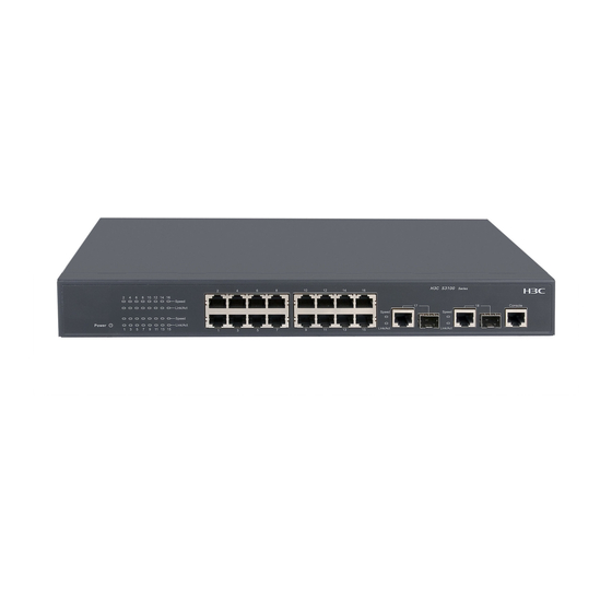
Page 5: S3100-16Tp-Ei-W
Installation Manual (For Soliton) H3C S3100 Series Ethernet Switches Chapter 1 Product Introduction RPS DC input: Rate voltage range: 10.8 VDC to 13.2 VDC IV. Cooling system S3100-26TP-EI-W Ethernet switches cool off naturally. 1.2.2 S3100-16TP-EI-W I. Front panel S3100-16TP-EI-W Ethernet... - Page 6 Installation Manual (For Soliton) H3C S3100 Series Ethernet Switches Chapter 1 Product Introduction (1) AC power socket (2) Grounding screw Figure 1-4 Rear panel of an S3100-16TP-EI-W Ethernet switch III. Side panel Each S3100-16TP-EI-W Ethernet switch provides a security slot, through which you can lock the device together with an irremovable object to prevent theft.
-
Page 7: S3100-8Tp-Ei-W
Installation Manual (For Soliton) H3C S3100 Series Ethernet Switches Chapter 1 Product Introduction V. Cooling system S3100-16TP-EI-W Ethernet switches cool off naturally. 1.2.3 S3100-8TP-EI-W I. Front panel S3100-8TP-EI-W Ethernet switches each provide eight auto-sensing 10/100Base-TX Ethernet ports, one 10/100/1000Base-T Ethernet port, one 100/1000Base-X SFP port, and one console port. -
Page 8: Introduction To Front Panel Leds
Input voltage range: 90 VAC to 264 VAC, 47Hz to 63Hz V. Cooling system S3100-8TP-EI-W Ethernet switches cool off naturally. 1.3 Introduction to Front Panel LEDs 1.3.1 Power LED Table 1-2 Description of the power LED on S3100 series Mark on the panel Status Description The switch is powered on. -
Page 9: Auto-Sensing 10/100Base-Tx Ethernet Port Status Led
In addition, there are an A/L LED and a D/S LED on each model of S3100 series. These two LEDs indicate the mode of the port status LEDs. When the A/L LED is on, the port status LEDs respectively indicate the active status and link status of ports. -
Page 10: 1000 Mbps Uplink Port Status Led
Installation Manual (For Soliton) H3C S3100 Series Ethernet Switches Chapter 1 Product Introduction 1.3.3 1000 Mbps Uplink Port Status LED Table 1-4 Description of 1000 Mbps uplink port status LED on S3100 series Mark on Status Description the panel The port is connected properly. -
Page 11: Sfp Modules Supported By S3100 Series Ethernet Switches
SFP-GE-LX-SM1490-BIDI Note: The types of SFP modules may vary over time. Consult H3C marketing personnel or technical support personnel to obtain the latest information about SFP modules. For specifications of SFP modules, refer to H3C Low End Series Ethernet Switches... -
Page 12: Chapter 2 Installation Preparation
2.2 Requirements on Environment S3100 Series Ethernet Switches must be used indoors. When you install your switch in a cabinet or on a desk, you must ensure: Enough space is reserved near the air-intake hole and the ventilation hole of the switch for heat dissipation of the switch chassis. -
Page 13: Cleanness Requirements
Installation Manual (For Soliton) H3C S3100 Series Ethernet Switches Chapter 2 Installation Preparation rustiness and corrosion of metal parts. If the relative humidity is too low, the captive screws may become loose due to the shrinking of insulation washers; in addition, electrostatic is more likely to be produced in a dry environment, which may damage the circuit of the switch. -
Page 14: Anti-Interference Requirements
S3100 Series Ethernet Switches are category-1 laser equipment. Caution: When an optional interface card of the S3100 Series Ethernet Switches is operating, avoid staring into the optical interface because the high-energy laser beam emitted from the optical fiber may hurt your eyes. - Page 15 Installation Manual (For Soliton) H3C S3100 Series Ethernet Switches Chapter 2 Installation Preparation Caution: These installation tools are not shipped with S3100 Series Ethernet Switches. You will have to prepare them beforehand.
-
Page 16: Chapter 3 Installation
Chapter 3 Installation Caution: On a mounting screw of the chassis of H3C S3100 Series Ethernet Switches, there is a seal labeled with H3C. You must keep it intact before asking the agent to maintain the switch. You must get the permission of the local agent before you can open the chassis. - Page 17 (2) Screw hole used to fix the switch to the mounting ear Figure 3-1 Appearance of a standard front mounting ear When you install S3100 Series Ethernet Switches into 19-inch standard cabinets, you should select front mounting ears with a proper length (L1 as shown in Figure 3-1) according to the physical dimensions of switches.
- Page 18 Installation Manual (For Soliton) H3C S3100 Series Ethernet Switches Chapter 3 Installation Figure 3-2 Fix front mounting ears (1) Place the switch horizontally in a proper position, and fix the other end of mounting ears to the front brackets with screws and captive nuts, as shown in Figure 3-3.
- Page 19 Slotted hole 2: Used to fix the guide rail to the front bracket Figure 3-4 Appearance of a guide rail Note: Guide rails purchased from H3C apply only to standard cabinets 1,000 mm (39.4 in) deep. Use other supports to substitute for guide rails in the case of other cabinet depths.
- Page 20 Installation Manual (For Soliton) H3C S3100 Series Ethernet Switches Chapter 3 Installation Figure 3-5 Install guide rails Hold the two sides of the switch and slide it gently along the guide rails into the cabinet until it is located in a proper position, as shown in Figure 3-6. Ensure that the bottom side of the guide rails and the switch are in close contact.
-
Page 21: Desk Mounting
(0.6 in) between devices if you need to stack switches one upon another. 3.1.3 Wall Mounting You can mount some models of S3100 Series Ethernet Switches on concrete walls or wood walls. Table 3-3 lists the models that support wall mounting. - Page 22 Installation Manual (For Soliton) H3C S3100 Series Ethernet Switches Chapter 3 Installation Table 3-3 Models supporting wall mounting Models supporting wall Subseries Hole distance (mm) mounting S3100-8TP-EI-W S3100 Ethernet 170 mm (6.69 in.) switches S3100-16TP-EI-W I. Introduction to screw and anchor kit...
-
Page 23: Magnet Mounting
Installation Manual (For Soliton) H3C S3100 Series Ethernet Switches Chapter 3 Installation Note: Drill two holes according to the sizes of anchor kits and screws so that anchor kits could go into the holes, only the edges could remain outside the wall, and the screws could be fixed on the wall tightly. - Page 24 Installation Manual (For Soliton) H3C S3100 Series Ethernet Switches Chapter 3 Installation I. Introduction to magnetic accessories A set of magnetic mounting accessories consists of one permanent magnets and one M3*6 countersunk head screws, as shown in Figure 3-11. Four sets of magnetic mounting accessories are needed for each S3100 switch.
- Page 25 Installation Manual (For Soliton) H3C S3100 Series Ethernet Switches Chapter 3 Installation (1) Blind nut in the dent of the switch bottom (2) Permanent magnet (3) M3*6 countersunk head screw Figure 3-12 Magnet mounting Caution: Apply magnet mounting to only the above four models. Otherwise, a falloff or mis-operation may occur.
-
Page 26: Connection Of Power Cable And Grounding Cable
Installation Manual (For Soliton) H3C S3100 Series Ethernet Switches Chapter 3 Installation 3.2 Connection of Power Cable and Grounding Cable 3.2.1 Connecting AC Power Cable I. AC power socket (recommended) You are recommended to use a mono-phase three-core power socket with a neutral point or a multi-function power socket for computers. -
Page 27: Connecting Dc Power Cable
Installation Manual (For Soliton) H3C S3100 Series Ethernet Switches Chapter 3 Installation 3.2.2 Connecting DC Power Cable I. 12V-RPS DC power cable connection for S3100-26TP-EI-W Ethernet switch Pin Number Designation Pin Number Designation — — RPS_pres — — Control Pin... -
Page 28: Connecting Grounding Cable
Installation Manual (For Soliton) H3C S3100 Series Ethernet Switches Chapter 3 Installation Direction A Direction B Figure 3-16 12V-RPS DC power cable Connect one end of the delivered AC power cable to the power socket of the RPS power module and the other end to the socket of an external AC power supply. - Page 29 Installation Manual (For Soliton) H3C S3100 Series Ethernet Switches Chapter 3 Installation of the switch should be connected to the construction engineering ground of the equipment room.) (1) Power input (2) Grounding screw (3) Protection grounding cable (4) Grounding strip...
- Page 30 Installation Manual (For Soliton) H3C S3100 Series Ethernet Switches Chapter 3 Installation (1) AC power socket (2) Grounding screw (3) Power transformer (4) PE cable (5) 3-core cable for AC power input (6) Ethernet switch Figure 3-19 Ground the switch through AC PE cable For a DC-powered switch (–48 VDC), if none of the first two conditions is available,...
-
Page 31: Connecting Optical Fiber
Installation Manual (For Soliton) H3C S3100 Series Ethernet Switches Chapter 3 Installation 3.3 Connecting Optical Fiber Caution: After a switch starts, the optical port may emit invisible radial when there is no optical connector connected to it and the protective cap is removed from it. -
Page 32: Connecting Console Cable
Installation Manual (For Soliton) H3C S3100 Series Ethernet Switches Chapter 3 Installation RJ-45 Signal Direction DB-9 → — → → → 3.4.2 Connecting Console Cable Follow these steps to connect a terminal device, a PC for example, to the switch: Step 1: Connect the DB-9 female connector of the console cable to the serial port of the PC or the terminal device used to configure the switch. -
Page 33: Chapter 4 First Power-On
Installation Manual (For Soliton) H3C S3100 Series Ethernet Switches Chapter 4 First Power-on Chapter 4 First Power-on 4.1 Establishing Configuration Environment The following figure shows the configuration environment you will establish: In this environment, a terminal (a PC in this example) is connected to the console port of the switch through the console cable. - Page 34 Installation Manual (For Soliton) H3C S3100 Series Ethernet Switches Chapter 4 First Power-on Select [Start/Program/Accessories/Communications/HyperTerminal] to enter the HyperTerminal window, where click the icon to establish a new connection. The system displays the Connection Description interface, as shown in the following figure.
- Page 35 Installation Manual (For Soliton) H3C S3100 Series Ethernet Switches Chapter 4 First Power-on Click <OK> after selecting a serial port and the system pops up the following interface. In the interface, set the bits per second to 9600, data bits to 8, parity check to none, stop bits to 1, and flow control to none.
-
Page 36: Booting Switch
4.4.2 Powering on the Switch All the S3100 series Ethernet switches have the same BOOTROM display style. This document takes the BOOTROM display of the S3100-26TP-EI-W switch as example: Starting.. - Page 37 Installation Manual (For Soliton) H3C S3100 Series Ethernet Switches Chapter 4 First Power-on Copyright(c) 2004-2007 Hangzhou H3C Technologies Co., Ltd. Creation date : Dec 8 2007, 13:47:55 CPU Clock Speed : 200MHz BUS Clock Speed : 33MHz Memory Size : 64MB...
-
Page 38: Changing The Startup Mode
Installation Manual (For Soliton) H3C S3100 Series Ethernet Switches Chapter 4 First Power-on ..................................................OK! Starting at 0x80100000... User interface aux0 is available. Press ENTER to get started. 4.4.3 Changing the Startup Mode By default, the system starts up in fast mode. If you want to change the startup mode to normal, press <Ctrl+B>... - Page 39 Enter 0, the system reboots in normal mode and displays the following information: Starting..*********************************************************** H3C S3100-26TP-EI-W BOOTROM, Version 517 *********************************************************** Copyright(c) 2004-2007 Hangzhou H3C Technologies Co., Ltd. Creation date : Dec 8 2007, 13:47:55 CPU Clock Speed : 200MHz...
- Page 40 Note: The H3C S3100 Series Switches provides abundant command views. For detailed descriptions about the configuration commands and CLI, refer to H3C S3100 Series Ethernet Switches Operation Manual (For Soliton) and H3C S3100 Series Ethernet Switches Command Manual (For Soliton).
-
Page 41: Chapter 5 Boot Rom And Host Software Loading
Installation Manual (For Soliton) H3C S3100 Series Ethernet Switches Chapter 5 Boot ROM and Host Software Loading Chapter 5 Boot ROM and Host Software Loading Traditionally, the loading of switch software is accomplished through the serial port. This approach is slow, inconvenient, and cannot be used for remote real-time loading. -
Page 42: Boot Menu
Take S3100-26TP-EI-W switch as example. After the switch is powered on, the system displays: Starting..*********************************************************** H3C S3100-26TP-EI-W BOOTROM, Version 517 *********************************************************** Copyright(c) 2004-2007 Hangzhou H3C Technologies Co., Ltd. Creation date : Dec 8 2007, 13:47:55 CPU Clock Speed : 200MHz BUS Clock Speed : 33MHz... -
Page 43: Loading Software Using Xmodem Through Console Port
Installation Manual (For Soliton) H3C S3100 Series Ethernet Switches Chapter 5 Boot ROM and Host Software Loading Note: To enter the Boot Menu, you should press <Ctrl+B> within five seconds after the information “Press Ctrl-B to enter Boot Menu...” appears. Otherwise, the system starts to decompress the program;... - Page 44 Installation Manual (For Soliton) H3C S3100 Series Ethernet Switches Chapter 5 Boot ROM and Host Software Loading II. Loading Boot ROM software Follow these steps to load the Boot ROM software: Step 1: At the prompt "Enter your choice (0-9):" in the Boot Menu, press <6> or <Ctrl+U>, and then press <Enter>...
- Page 45 Installation Manual (For Soliton) H3C S3100 Series Ethernet Switches Chapter 5 Boot ROM and Host Software Loading Figure 5-1 Properties dialog box Figure 5-2 Console port configuration dialog box Step 5: Click the <Disconnect> button to disconnect the HyperTerminal from the switch...
- Page 46 Installation Manual (For Soliton) H3C S3100 Series Ethernet Switches Chapter 5 Boot ROM and Host Software Loading Figure 5-3 Call and disconnect buttons Note: The new bits per second takes effect only after you disconnect and reconnect the terminal emulation program.
- Page 47 Installation Manual (For Soliton) H3C S3100 Series Ethernet Switches Chapter 5 Boot ROM and Host Software Loading Figure 5-5 Sending file page After the download completes, the system displays the following information: Loading ...CCCCCCCCCC done! Note: You do not need to reset the HyperTerminal’s bits per second and can skip the last step if you have chosen 9600 bps.
-
Page 48: Loading Software Using Tftp Through Ethernet Port
Step 2: Run the TFTP server program on the TFTP server, and specify the path of the program to be loaded. Caution: TFTP server program is not provided with the H3C Series Switches. Step 3: Run the terminal emulation program on the configuration PC. Start the switch. Then enter the Boot Menu. -
Page 49: Loading Software Using Ftp Through Ethernet Port
Installation Manual (For Soliton) H3C S3100 Series Ethernet Switches Chapter 5 Boot ROM and Host Software Loading 2. Set FTP protocol parameter 3. Set XMODEM protocol parameter 0. Return to boot menu Enter your choice(0-3): Step 4: Enter 1 to download the Boot ROM software using TFTP. Then set the following... - Page 50 Installation Manual (For Soliton) H3C S3100 Series Ethernet Switches Chapter 5 Boot ROM and Host Software Loading II. Loading Boot ROM software Switch Console port Ethernet port FTP Client FTP Server Figure 5-7 Local loading using FTP Step 1: As shown in Figure 5-7, connect the switch through an Ethernet port to the FTP server, and connect the switch through the console port to the configuration PC.
-
Page 51: Remote Software Loading
Installation Manual (For Soliton) H3C S3100 Series Ethernet Switches Chapter 5 Boot ROM and Host Software Loading Step 6: Enter Y to start file downloading or N to return to the Boot ROM update menu. If you enter Y, the system begins to download and update the program. Upon completion, the system displays the following information: Loading........done... - Page 52 Installation Manual (For Soliton) H3C S3100 Series Ethernet Switches Chapter 5 Boot ROM and Host Software Loading 220 WFTPD 2.0 service (by Texas Imperial Software) ready for new user User(none):abc 331 Give me your password, please Password: 230 Logged in successfully [ftp] get s3100-EI.bin...
-
Page 53: Remote Loading Using Tftp
Installation Manual (For Soliton) H3C S3100 Series Ethernet Switches Chapter 5 Boot ROM and Host Software Loading 5.3.2 Remote Loading Using TFTP The remote loading by using TFTP is similar to the remote loading by using FTP. The only difference is that it is TFTP that you use when loading software to the switch. In this case, the switch can only be used as a TFTP client. -
Page 54: Chapter 6 Maintenance And Troubleshooting
Installation Manual (For Soliton) H3C S3100 Series Ethernet Switches Chapter 6 Maintenance and Troubleshooting Chapter 6 Maintenance and Troubleshooting 6.1 Software Loading Failure If software loading fails, the system keeps running in original version. In this case, check if the physical ports are properly connected: If not, reconnect them correctly and restart the loading procedure. -
Page 55: Missing Boot Rom Password
Installation Manual (For Soliton) H3C S3100 Series Ethernet Switches Chapter 6 Maintenance and Troubleshooting 9. Set switch startup mode 0. Reboot Enter your choice(0-9): Select <7> and restart the switch. After that, the system will skip the configuration file. 6.2.2 Missing Boot ROM Password Please contact your agent. - Page 56 Installation Manual (For Soliton) H3C S3100 Series Ethernet Switches Chapter 6 Maintenance and Troubleshooting Flow control: None Terminal emulation: VT100.
Need help?
Do you have a question about the S3100 Series and is the answer not in the manual?
Questions and answers