H3C S3100 Series Installation Manual
Ethernet switches
Hide thumbs
Also See for S3100 Series:
- Command manual (1186 pages) ,
- Operation manual (1057 pages) ,
- Installation manual (56 pages)

Related Manuals for H3C S3100 Series


Summary of Contents for H3C S3100 Series
- Page 1 H3C S3100 Series Ethernet Switches Installation Manual Hangzhou H3C Technologies Co., Ltd. http://www.h3c.com Manual Version: 20090601-C-1.06...
- Page 2 SecPro, SecPoint, SecEngine, SecPath, Comware, Secware, Storware, NQA, VVG, V G, V G, PSPT, XGbus, N-Bus, TiGem, InnoVision and HUASAN are trademarks of Hangzhou H3C Technologies Co., Ltd. All other trademarks that may be mentioned in this manual are the property of their respective owners.
-
Page 3: About This Manual
About This Manual Organization H3C S3100 Series Ethernet Switches Installation Manual is organized as follows: Chapter Contents Introduces the characteristics and technical specifications of 1 Product Introduction S3100 Series Ethernet Switches. Introduces the installation preparation and precaution of 2 Installation Preparation S3100 Series Ethernet Switches. -
Page 4: Related Documentation
Command Manual commands. Obtaining Documentation You can access the most up-to-date H3C product documentation on the World Wide Web at this URL: http://www.h3c.com. The following are the columns from which you can obtain different categories of product documentation: [Products & Solutions]: Provides information about products and technologies. - Page 5 Environmental Protection This product has been designed to comply with the requirements on environmental protection. For the proper storage, use and disposal of this product, national laws and regulations must be observed.
-
Page 6: Table Of Contents
Table of Contents 1 Product Introduction ·································································································································1-1 Overview ·················································································································································1-1 S3100-SI Series Ethernet Switches ································································································1-1 S3100-EI Series Ethernet Switches ································································································1-4 Introduction to S3100-SI Series Ethernet Switches················································································1-7 S3100-52TP-SI································································································································1-7 S3100-26TP-SI································································································································1-8 S3100-16TP-SI································································································································1-9 S3100-8TP-SI································································································································1-11 S3100-26T-SI ································································································································1-12 S3100-16T-SI ································································································································1-13 S3100-8T-SI ··································································································································1-14 S3100-26C-SI································································································································1-15 S3100-16C-SI································································································································1-16 S3100-8C-SI··································································································································1-17 Introduction to S3100-EI Series Ethernet Switches··············································································1-19 S3100-26TP-EI······························································································································1-19 S3100-16TP-EI······························································································································1-20 S3100-8TP-EI································································································································1-22... - Page 7 Wall Mounting································································································································3-10 Magnet Mounting···························································································································3-12 Connecting Grounding Cable················································································································3-14 When a Grounding Strip is Available·····························································································3-14 Where a Grounding Conductor Can be Buried ·············································································3-16 In Other Installation Sites ··············································································································3-16 Connection of Power Cable ··················································································································3-18 Connecting AC Power Cable·········································································································3-18 Connecting DC Power Cable ········································································································3-19 Installing an Expansion Interface Module ·····························································································3-21 Connecting Optical Fiber ······················································································································3-22 Installation Verification ··························································································································3-23...
-
Page 8: Product Introduction
Product Introduction Overview The H3C S3100 Series Ethernet Switches are high-performance, high-density, easy-to-install, NMS-manageable intelligent Ethernet switches which support wire-speed Layer 2 switching. Table 1-1 Models of the H3C S3100 Series Ethernet Switches Name Subseries Model S3100-8TP-SI S3100-16TP-SI S3100-TP-SI S3100-26TP-SI... -
Page 9: S3100-26Tp-Si································································································································1
Model S3100-52TP- SI S3100-26TP- SI S3100-16TP-SI S3100-8TP-SI 24 × auto-sensing 16 x auto-sensing 8 × auto-sensing 48 x auto-sensing 10/100Base-TX 10/100Base-TX 10/100Base-TX 10/100Base-TX Ethernet port Ethernet port Ethernet port Ethernet port 2 × 1000 Mbps 2 x 1000Mbps 1 × 1000 Mbps 2 x auto-sensing Combo port Combo port... - Page 10 Item S3100-26T-SI S3100-16T-SI S3100-8T-SI PoE (as powered Not supported Not supported Not supported device) System power 20 W 12 W 10 W consumption (full load) None None None Operating temperature 0°C to 45°C (30°F to 113°F) Relative humidity 10% to 90% (noncondensing) S3100-C-SI Series Table 1-4 Technical specifications for the S3100-C-SI series...
-
Page 11: S3100-Ei Series Ethernet Switches
Item S3100-26C-SI S3100-16C-SI S3100-8C-SI Both DC-powered switch and AC-powered switch are available to each model. The AC-powered switch supports only AC input, and the DC-powered switch supports only DC input. AC input: Rated voltage range: 100 VAC to 240 VAC, 50 Hz/60 Hz Power system Input voltage range: 90 VAC to 264 VAC, 47 Hz to 63 Hz DC input:... - Page 12 Item S3100-26TP-EI S3100-16TP-EI S3100-8TP-EI 24 × auto-sensing 16 × auto-sensing 8 × auto-sensing 10/100Base-TX 10/100Base-TX 10/100Base-TX Ethernet port Ethernet port Ethernet port 2 × 1000 Mbps Combo 2 × 1000 Mbps Combo 1 × 1000 Mbps Combo port port port Number of fixed ports Note: A 100/1000Base-X SFP port and a corresponding auto-sensing 10/100/1000Base-T Ethernet port form a Combo port.
- Page 13 Item S3100-26TP-PWR-EI S3100-16TP-PWR-EI S3100-8TP-PWR-EI S3100-26TP-PWR-EI Ethernet switches support AC input and DC input. S3100-16TP-PWR-EI/S3100-8TP-PWR-EI Ethernet switches support only AC input. AC input: Power system Rated voltage range: 100 VAC to 240 VAC, 50 Hz/60 Hz Input voltage range: 90 VAC to 264 VAC, 47 Hz to 63 Hz DC input: Rated voltage range: –52 VDC to –56 VDC System...
-
Page 14: Introduction To S3100-Si Series Ethernet Switches
Item S3100-26C-EPON-EI S3100-16C-EPON-EI S3100-8C-EPON-EI AC input: Power system Rated voltage range: 100 VAC to 240 VAC, 50 Hz/60 Hz Input voltage range: 90 VAC to 264 VAC, 47 Hz to 63 Hz PoE (as powered Not supported Not supported Not supported device) System power consumption (full... -
Page 15: S3100-26Tp
For details about LEDs on the front panel, refer to section “Front Panel LEDs of the S3100-TP-SI and S3100-TP-EI Series”. Rear panel Each S3100-52TP-SI Ethernet switch provides one console port on its rear panel. Figure 1-25 shows the rear panel of an S3100-52TP-SI Ethernet switch. Figure 1-2 Rear panel of an S3100-52TP-SI Ethernet switch (1) Console port (2) Grounding screw... -
Page 16: S3100-16Tp
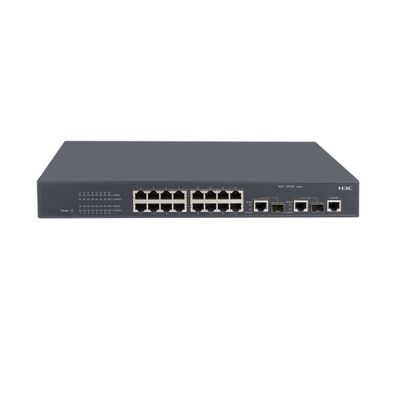
Figure 1-3 Front panel of an S3100-26TP-SI Ethernet switch (1) Auto-sensing 10/100Base-TX port Speed LED (green) (2) Auto-sensing 10/100Base-TX port (3) Combo port Speed LED (green) (4) Auto-sensing 10/100/1000Base-T port (5) Console port (6) 100/1000Base-X SFP port (7) LINK/ACT LED (green) (8) Power LED (PWR) For details about LEDs on the front panel, refer to section “Front Panel LEDs of the S3100-TP-SI and... - Page 17 Combo port. For each Combo port, either the SFP port or the corresponding 10/100/1000Base- T Ethernet port can be used at a time. Figure 1-5 shows the front panel of an S3100-16TP-SI Ethernet switch. Figure 1-5 Front panel of an S3100-16TP-SI Ethernet switch (1) Auto-sensing 10/100Base-TX port Speed LED (green) (2) Auto-sensing 10/100Base-TX port (3) Combo port Speed LED (green)
-
Page 18: S3100-8Tp
S3100-8TP-SI Front panel S3100-8TP-SI Ethernet switches each provide eight auto-sensing 10/100Base-TX Ethernet ports, one auto-sensing 10/100/1000Base-T Ethernet ports, one 100/1000Base-X SFP ports, and one console port. The SFP port and the auto-sensing 10/100/1000Base- T Ethernet port form a Combo port. For the Combo port, either the SFP port or the 10/100/1000Base- T Ethernet port can be used at a time. -
Page 19: S3100-26T
Cooling system The S3100-8TP-SI cools off naturally. S3100-26T-SI Front panel S3100-26T-SI Ethernet switches each provide twenty-four auto-sensing 10/100Base-TX Ethernet ports, two 10/100/1000Base-T Ethernet ports, and one console port. Figure 1-9 shows the front panel of an S3100-26T-SI Ethernet switch. Figure 1-9 Front panel of an S3100-26T-SI Ethernet switch (1) Power LED (2) A/L LED (3) D/S LED... -
Page 20: S3100-16T
Cooling system The S3100-26T-SI cools off naturally. S3100-16T-SI Front panel S3100-16T-SI Ethernet switches each provide sixteen auto-sensing 10/100Base-TX Ethernet ports, one 10/100/1000Base-T Ethernet port, and one console port. Figure 1-11 shows the front panel of an S3100-16T-SI Ethernet switch. Figure 1-11 Front panel of an S3100-16T-SI Ethernet switch (1) Power LED (2) A/L LED (3) D/S LED... -
Page 21: S3100-8T
Cooling system The S3100-16T-SI cools off naturally. S3100-8T-SI Front panel S3100-8T-SI Ethernet switches each provide eight auto-sensing 10/100Base-TX Ethernet ports, one 10/100/1000Base-T Ethernet port, and one console port. Figure 1-13 shows the front panel of an S3100-8T-SI Ethernet switch. Figure 1-13 Front panel of an S3100-8T-SI Ethernet switch (1) Power LED (2) A/L LED (3) D/S LED... -
Page 22: S3100-26C
Input voltage range: 90 VAC to 264 VAC, 47 Hz to 63 Hz Cooling system The S3100-8T-SI cools off naturally. S3100-26C-SI Both AC-powered switches and DC-powered switches are available to this model. Front panel S3100-26C-SI Ethernet switches each provide twenty-four auto-sensing 10/100Base-TX Ethernet ports, two expansion slots, and one console port. -
Page 23: S3100-16C
Figure 1-17 shows the rear panel of an S3100-26C-SI DC-powered Ethernet switch. Figure 1-17 Rear panel of an S3100-26C-SI DC-powered Ethernet switch (1) DC input terminal block (2) Grounding screw Power system S3100-26C-SI AC-powered Ethernet switches: Rated voltage range: 100 VAC to 240 VAC, 50 Hz/60 Hz Input voltage range: 90 VAC to 264 VAC, 47 Hz to 63 Hz S3100-26C-SI DC-powered Ethernet switches: Rated voltage range: –48 VDC to –60 VDC... -
Page 24: S3100-8C
With a PoE card inserted in one expansion slot, an S3100-16C-SI Ethernet switch will be a powered device (PD). In this case, the other expansion slot becomes unavailable. For details about LEDs on the front panel, refer to section “Front Panel LEDs of the S3100-T-SI/S3100-C-SI/S3100-TP-PWR-EI/ S3100-C-EPON-EI Series”. - Page 25 Front panel S3100-8C-SI Ethernet switches each provide eight auto-sensing 10/100Base-TX Ethernet ports, one expansion slot, and one console port. S3100-8C-SI Ethernet switches have the same front panel, as shown in Figure 1-21. Figure 1-21 Front panel of an S3100-8C-SI Ethernet switch (1) Power LED (2) A/L LED (3) D/S LED...
-
Page 26: Introduction To S3100-Ei Series Ethernet Switches
Power system S3100-8C-SI AC-powered Ethernet switches: Rated voltage range: 100 VAC to 240 VAC, 50 Hz/60 Hz Input voltage range: 90 VAC to 264 VAC, 47 Hz to 63 Hz S3100-8C-SI DC-powered Ethernet switches: Rated voltage range: –48 VDC to –60 VDC Input voltage range: –36 VDC to –72 VDC Cooling system The S3100-8C-SI cools off naturally. -
Page 27: S3100-16Tp
Figure 1-25 Rear panel of an S3100-26TP-EI AC-powered Ethernet switch (1) Grounding screw (2) AC input terminal block Figure 1-26 shows the rear panel of an S3100-26TP-EI DC-powered Ethernet switch. Figure 1-26 Rear panel of an S3100-26TP-EI DC-powered Ethernet switch (1) Grounding screw (2) DC input terminal block Power system... - Page 28 Figure 1-27 Front panel of an S3100-16TP-EI Ethernet switch (1) Auto-sensing 10/100Base-TX port Speed LED (green) (2) Auto-sensing 10/100Base-TX port (3) Combo port Speed LED (green) (4) Auto-sensing 10/100/1000Base-T port (5) Console port (6) 100/1000Base-X SFP port (7) LINK/ACT LED (green) (8) Power LED (PWR) For details about LEDs on the front panel, refer to section “Front Panel LEDs of the S3100-TP-SI and...
-
Page 29: S3100-8Tp
S3100-16TP-EI DC-powered Ethernet switches: Rated voltage range: –48 VDC to –60 VDC Input voltage range: –36 VDC to –72 VDC Cooling system The S3100-16TP-EI cools off naturally. S3100-8TP-EI Both AC-powered switches and DC-powered switches are available to this model. Front panel S3100-8TP-EI Ethernet switches each provide eight auto-sensing 10/100Base-TX Ethernet ports, one auto-sensing 10/100/1000Base-T Ethernet ports, one 100/1000Base-X SFP ports, and one console port. -
Page 30: S3100-26Tp-Pwr
Figure 1-31 Rear panel of an S3100-8TP-EI AC-powered Ethernet switch (1) Grounding screw (2) AC input terminal block Figure 1-32 shows the rear panel of an S3100-8TP-EI DC-powered Ethernet switch. Figure 1-32 Rear panel of an S3100-8TP-EI DC-powered Ethernet switch (1) Grounding screw (2) DC input terminal block Power system... - Page 31 Figure 1-33 Front panel of an S3100-26TP-PWR-EI Ethernet switch (1) Auto-sensing 10/100Base-TX Ethernet port status LED (2) LINK LED for Combo port (3) Console port (4) Power LED (PWR) (5) A/L LED (6) D/S LED (7) Mode button (8) ACT LED for Combo port For details about LEDs on the front panel, refer to section “Front Panel LEDs of the S3100-T-SI/S3100-C-SI/S3100-TP-PWR-EI/ S3100-C-EPON-EI...
-
Page 32: S3100-16Tp-Pwr
Only the recommended RPS can be used for S3100-26TP-PWR-EI Ethernet switches. The –48 VDC in the equipment room cannot be used directly. Otherwise, the device may be damaged. Cooling system The S3100-26TP-PWR-EI has four fans for heat dissipation. S3100-16TP-PWR-EI Front panel S3100-16TP-PWR-EI Ethernet switches each provide sixteen auto-sensing 10/100Base-TX Ethernet ports, two 10/100/1000Base-T Ethernet ports, two 100/1000Base SFP ports, and one console port. - Page 33 Rear panel Figure 1-36 Rear panel of an S3100-16TP-PWR-EI Ethernet switch (1) AC power socket (2) Grounding screw Side panel Each S3100-16TP-PWR-EI Ethernet switch provides a security slot, through which you can lock the device together with an irremovable object to prevent theft. The security slot is located at the rear end of the left side panel, as shown in Figure 1-37.
-
Page 34: S3100-8Tp-Pwr
S3100-8TP-PWR-EI Front panel S3100-8TP-PWR-EI Ethernet switches each provide eight auto-sensing 10/100Base-TX Ethernet ports, one 10/100/1000Base-T Ethernet port, one 100/1000Base SFP ports, and one console port. The SFP port and the 10/100/1000Base-T Ethernet port form a Combo port. Either the SFP port or the 10/100/1000Base-T Ethernet port can be used at a time. -
Page 35: S3100-26C-Epon
If the left screw hole above the security slot is used, the security slot cannot be used. Power system S3100-8TP-PWR-EI Ethernet switches support AC input. Rate voltage range: 100 VAC to 240 VAC, 50 Hz/60 Hz Input voltage range: 90 VAC to 264 VAC, 47 HZ to 63 Hz Cooling system The S3100-8TP-PWR-EI has two fans for heat dissipation. - Page 36 Rear panel Figure 1-41 Rear panel of an S3100-26C-EPON-EI Ethernet switch (1) AC power socket (2) Grounding screw Power system S3100-26C-EPON-EI Ethernet switches support AC input. Rated voltage range: 100 VAC to 240 VAC, 50 Hz/60 Hz Input voltage range: 90 VAC to 264 VAC, 47 Hz to 63 Hz Cooling system The S3100-26C-EPON-EI has one fan for heat dissipation.
- Page 37 Rear panel Figure 1-43 Rear panel of an S3100-16C-EPON-EI Ethernet switch (1) AC power socket (2) Grounding screw Power system S3100-16C-EPON-EI Ethernet switches support AC input. Rated voltage range: 100 VAC to 240 VAC, 50 Hz/60 Hz Input voltage range: 90 VAC to 264 VAC, 47 Hz to 63 Hz Cooling system The S3100-16C-EPON-EI cools off naturally.
-
Page 38: Introduction To Front Panel Leds
Rear panel Figure 1-45 Rear panel of an S3100-8C-EPON-EI Ethernet switch (1) AC power socket (2) Grounding screw Power system S3100-8C-EPON-EI Ethernet switches support AC input. Rated voltage range: 100 VAC to 240 VAC, 50 Hz/60 Hz Input voltage range: 90 VAC to 264 VAC, 47 Hz to 63 Hz Cooling system The S3100-8C-EPON-EI cool off naturally. -
Page 39: Front Panel Leds Of The S3100-Tp-Si And S3100-Tp-Ei Series
Table 1-9 Description of port status LEDs on S3100-T-SI, S3100-C-SI, S3100-TP-PWR-EI, and S3100-C-EPON-EI series Ethernet switches Port status Port status LED Description mode LED The port is in the active state and there is traffic Blinking on the port. Yellow LED (left) The port is in the active state but there is no The A/L LED... - Page 40 Port Status LED Table 1-12 describes the Link/Act LED of the auto-sensing 10/100Base-TX port. Table 1-12 Description of the Link/Act LED on the S3100-TP-SI and S3100-TP-EI series Status Description The port is connected properly. The port is in the active state and there is traffic Blinking Link/Act LED (green) on the port.
-
Page 41: Sfp Modules Supported By S3100 Ethernet Switches
1000 Mbps BIDI module SFP-GE-LX-SM1490-BIDI The types of SFP modules may vary over time. Consult H3C marketing personnel or technical support personnel to obtain the latest information about SFP modules. For specifications of SFP modules, refer to H3C Low End Series Ethernet Switches Pluggable Module Manual. - Page 42 Table 1-17 ONU module support of the S3100 series Number of Required or Switch model ONU module model ONU modules optional S3100-8C-SI Optional 1000Base-PX10 (LS6M1PU1SA) S3100-16C-SI Optional 1000Base-PX20 (LS6M1PU1SB) S3100-26C-SI Optional S3100-8C-EPON-EI Required S3100-16C-EPON-EI Required 1000Base-PX20 (LS6M2PU1SB) 1 required S3100-26C-EPON-EI 1 optional All models of ONU modules look alike.
- Page 43 Item Specifications Medium 9/125 µm single-mode fiber 1000Base- PX10: 10 km (6.21 miles) Maximum transmission distance 1000Base- PX20: 20 km (12.43 miles) For how to install and remove an ONU module, refer to section ”Installing an Expansion Interface Module”. Table 1-19 describes the LED indications.
-
Page 44: Installation Preparation
Requirements on Environment S3100 Series Ethernet Switches must be used indoors. When you install your switch in a cabinet or on a desk, you must ensure: Enough space is reserved near the air-intake hole and the ventilation hole of the switch for heat dissipation of the switch chassis. -
Page 45: Cleanness Requirements
For the temperature and humidity requirements of different models, refer to section “Overview”. Cleanness Requirements Dust is a potential hazard to the safe operation of the switch. Falling on the equipment, it may cause electrostatic adsorption, and hence result in poor contact of the metal connectors or connection points. This is more likely to happen when the indoor relative humidity is low;... -
Page 46: Laser Usage Security
S3100 Series Ethernet Switches are category-1 laser equipment. When an optional interface card of the S3100 Series Ethernet Switches is operating, avoid staring into the optical interface because the high-energy laser beam emitted from the optical fiber may hurt your eyes. -
Page 47: Installation
Installation On a mounting screw of the chassis of the H3C S3100 Series Ethernet Switches, there is a seal labeled with H3C. You must keep it intact before asking the agent to maintain the switch. You must get the permission of the local agent before you can open the chassis. Otherwise, you will be responsible for irreversible damages caused by your operations. - Page 48 (1) Screw hole used to fix the mounting ear to the cabinet (Use one M6 screw) When you install S3100 Series Ethernet Switches into 19-inch standard cabinets, you should select front mounting ears with a proper length (L1 as shown in...
-
Page 49: S3100-26C-Epon-Ei ····················································································································1
Table 3-3 Selection of mounting ear for S3100 Series Ethernet Switches Configuration Configuration Physical dimensions (H Model type of front type of rear × W × D) mounting ear mounting ear S3100-26T-SI 42 × 436 × 240 mm S3100-26C-SI Standard (1.65 ×... - Page 50 (3) Slotted hole 2: Used to fix the guide rail to the front bracket Guide rails purchased from H3C apply only to standard cabinets 1,000 mm (39.4 in.) deep. Use other supports to substitute for guide rails in the case of other cabinet depths.
- Page 51 Figure 3-5 Fix front mounting ears (2) (1) Front square-holed bracket (2) Front panel (3) Front mounting ear Use front mounting ears and a tray to install a switch Follow these steps to install a switch into a 19-inch standard cabinet: Wear an ESD-preventive wrist strap to check the grounding and stability of the cabinet.
- Page 52 Figure 3-6 Fix front mounting ears and load-bearing screws (1) Load-bearing screw (2) Optional positions for Load-bearing screw (3) Front panel (4) Front mounting ear (5) Screw used to fix front mounting ears to the switch There are three positions to mount a load-bearing screw on both sides of a switch. You should select a proper position according to the actual requirements.
- Page 53 Figure 3-8 Fix front and rear mounting ears (1) Front square-holed bracket (2) Load-bearing screw: Used to bear the weight (3) Rear panel (4) Rear square-holed bracket (5) Rear mounting ear (6) Screw used to fix rear mounting ears to rear brackets (7) Front mounting ear After the switch is pushed into the cabinet, ensure that the upper edge of rear mounting ears is tightly contacted with the load-bearing screw, as shown in...
- Page 54 Fix the other end of the front mounting ears to the front brackets with screws and captive nuts and ensure that front and rear mounting ears have fixed the switch in the cabinet securely, as shown in Figure 3-10. Figure 3-10 Effect diagram of front and rear mounting ear installation (2) (1) (2) (1) Load-bearing screw (2) Rear mounting ear...
- Page 55 Figure 3-11 Install guide rails Hold the two sides of the switch and slide it gently along the guide rails into the cabinet until it is located in a proper position, as shown in Figure 3-12. Ensure that the bottom side of the guide rails and the switch are in close contact.
-
Page 56: Desk Mounting
1.5 cm (0.6 in.) between devices if you need to stack switches one upon another. Wall Mounting You can mount some models of S3100 Series Ethernet Switches on concrete walls or wood walls. Table lists the models that support wall mounting. - Page 57 Introduction to screw and anchor kit Figure 3-14 Figure 3-15 show the recommended sizes (in mm) of screws and anchor kits used for mounting: Figure 3-14 Screw Figure 3-15 Anchor kit (1) Outside edge of anchor kit Installation procedure The wall-mounting procedure is as follows: As shown in Figure 3-16, drill two holes 5 mm across in the wall on the same horizontal line, with a...
-
Page 58: Magnet Mounting
Figure 3-16 Wall mounting X mm 1.5 mm(Min) Align the two installation holes at the bottom of the switch with these two screws to hang the switch. When mounting the switch, keep the Ethernet ports of the switch facing downwards and the two sides with ventilation holes vertical to the ground. - Page 59 Installation procedure Follow these steps to complete magnet mounting: As shown in Figure 3-18, use a Phillips screwdriver to pass the countersunk head screw through the round hole at the center of the permanent magnet, fasten it to a blind nut in the dent of the switch bottom, and ensure that the permanent magnet and the switch are fastened reliably.
-
Page 60: Connecting Grounding Cable
Apply magnet mounting to only the above two models. Otherwise, a falloff or mis-operation may occur. Select the installation location carefully. In the case of poor surface, magnet mounting may not be reliable. Put the device at a stable place free from vibrations or shocks. Otherwise, personal injuries or equipment damage may occur. - Page 61 Step 3: Fasten the grounding screw, which is attached with the OT terminal of the PGND cable, into the grounding screw hole with a screwdriver. Figure 3-19 Connect the PGND cable to the grounding hole of switch (1) Rear panel of the switch (2) Grounding sign (3) Grounding hole (4) OT terminal...
-
Page 62: Where A Grounding Conductor Can Be Buried
The fire main and lightning rod of a building are not suitable for grounding the switch. The ground wire of the switch should be connected to the grounding device for the equipment room. Where a Grounding Conductor Can be Buried When there is no grounding strip, but an area with exposed earth is available nearby where a grounding conductor can be buried, hammer a 0.5 m (1.64 ft.) or longer angle iron or steel tube into the earth. - Page 63 Figure 3-22 Ground through an AC power PE wire (1) Three-wire AC power input cable (2) Switch rear panel When the Switch is DC-powered For a DC-powered switch, if neither of the first two conditions mentioned above is available, ground the switch through the return wire (RTN) of the DC power supply.
-
Page 64: Connection Of Power Cable
Connection of Power Cable Connecting AC Power Cable AC power socket (recommended) You are recommended to use a mono-phase three-core power socket with a neutral point or a multi-function power socket for computers. The neutral point of the power in your building must be well grounded. -
Page 65: Connecting Dc Power Cable
Currently, only the S3100-TP-PWR-EI series Ethernet Switches are equipped with an AC power cord retainer to prevent the power cord from accidentally falling off. The location of the power cord retainer holder varies with S3100-TP-PWR-EI series Ethernet Switches. Check whether the PWR LED on the front panel of the switch is ON. If yes, the power is properly connected. - Page 66 Use a flat-blade screwdriver to loosen the two screws on the DC input terminal blocks. Connect the power ground return cable to the RTN(+) terminal and the power output cable to the NEG(-) terminal. Tighten the two screws respectively to fix the power cables. Check whether the PWR LED on the front panel of the switch is ON.
-
Page 67: Installing An Expansion Interface Module
Use cable ties to bind the two power cables to the protruding part at the back of the air filter, as shown in Figure 3-28. Insert the connector into the DC socket directly. Use the flat-blade screwdriver to fix the connector with screw 1 and screw 2 (delivered with the switch), as shown in Figure 3-29. -
Page 68: Connecting Optical Fiber
Keep the removed filler panel properly for future use. Step 3: Unwrap the interface module. Gently push the interface module in along the slot guide rails until the interface module is in close contact with the switch. Step 4: Tighten the captive screws with a Phillips screwdriver to fix the interface module. Removal procedure Step 1: Wear an ESD-preventive wrist strap, ensure a good skin contact and make sure that the ESD-preventive wrist strap is properly grounded. -
Page 69: Installation Verification
The following section describes the procedures to connect optical fiber to an ONU card. The procedures also apply to other subcards. Step 1: Remove the protective cap from the optical connector of the fiber. Step 2: Remove the protective cap from the PON interface of the ONU subcard. Step 3: Plug the optical connector into the PON interface of the ONU subcard. -
Page 70: First Power
First Power-on Establishing Configuration Environment Set up the configuration environment as follows: Connect a terminal (a PC in this example) to the console port on the switch with a console cable. Figure 4-1 Network diagram for configuration environment setup Connecting the Console Cable Console Cable The console cable is an 8-core shielded cable. -
Page 71: Connection Procedure
Table 4-1 Console cable connector pinouts and mapping relation RJ-45 Signal Direction DB-9 ← ← ← → — → → → Connection Procedure Follow these steps to connect a terminal device, a PC for example, to the switch: Step 1: Connect the DB-9 female connector of the console cable to the serial port of the PC or the terminal device used to configure the switch. - Page 72 Select [Start/Program/Accessories/Communications/HyperTerminal] enter HyperTerminal window, where click the icon to establish a new connection. The system displays the Connection Description interface, as shown in the following figure. Figure 4-3 Connection description interface of HyperTerminal Type in the name of the new connection in the connection description interface and click <OK>. The system pops up the following interface.
- Page 73 Figure 4-5 Setting serial port parameters Click <OK> after setting the serial port parameters, and the system enters the following interface. Figure 4-6 HyperTerminal Choose [Properties] in the HyperTerminal dialog box to enter the properties window. Click [Settings] to enter the following properties setting window, and select VT100 as the terminal emulation. Click <OK> when the selection is done.
-
Page 74: Booting Switch
Powering on the Switch All the S3100 series Ethernet switches have the same Boot ROM display style. This document takes the Boot ROM display of the S3100-16C-SI switch as example: Starting.. -
Page 75: Changing The Startup Mode
Mac Address : 000fe20f3100 Press Ctrl-B to enter Boot Menu... 2 The last line prompts you to enter the Boot Menu and waits two seconds for your response. The system has two startup modes: normal and fast. The normal startup mode spends a little more time than the fast startup mode because the former takes more self-test operations. - Page 76 0. Reboot Enter your choice(0-9): Enter 0, the system reboots in normal mode and displays the following information: Starting..*********************************************************** H3C S3100-16C-SI BOOTROM, Version 506 *********************************************************** Copyright(c) 2004-2007 Hangzhou H3C Technologies Co., Ltd. Creation date : Apr 15 2007, 10:12:36...
- Page 77 You can configure the switch now. The H3C S3100 Series Switches provides abundant command views. For detailed descriptions about the configuration commands and CLI, refer to H3C S3100 Series Ethernet Switches Operation Manual and H3C S3100 Series Ethernet Switches Command Manual.
-
Page 78: Boot Rom And Host Software Loading
Boot ROM and Host Software Loading Traditionally, the loading of switch software is accomplished through the serial port. This approach is slow, inconvenient, and cannot be used for remote real-time loading. To resolve these problems, the TFTP and FTP modules are introduced into the switch. With these modules, the software and files can be loaded through Ethernet port conveniently. -
Page 79: Boot Menu
Take S3100-16C-SI switch as example. After the switch is powered on, the system displays: Starting..*********************************************************** H3C S3100-16C-SI BOOTROM, Version 506 *********************************************************** Copyright(c) 2004-2007 Hangzhou H3C Technologies Co., Ltd. Creation date : Apr 15 2007, 10:12:36 CPU Clock Speed : 200MHz BUS Clock Speed : 33MHz... -
Page 80: Loading Software Using Xmodem Through Console Port
Enter your choice(0-9): Loading Software Using XModem Through Console Port Introduction to XModem XModem is a file transfer protocol that is widely used due to its simplicity and good performance. XModem transfers files via console port. It supports two types of data packets (128 bytes and 1 KB), two check methods (checksum and CRC), and error packet retransmission mechanism (generally the maximum number of retransmission attempts is ten). - Page 81 If you have chosen 9600 bps, you do not need to modify the HyperTerminal’s bits per second, and therefore you can skip Step 4 and 5 below and proceed to Step 6 directly. In this case, the system will not display the above information. Step 4: Select [File/Properties] in the HyperTerminal window, click <Configuration>...
- Page 82 Figure 5-2 Console port configuration dialog box Step 5: Click the <Disconnect> button to disconnect the HyperTerminal from the switch and then click the <Call> button to reconnect the HyperTerminal to the switch. Figure 5-3 Call and disconnect buttons The new bits per second takes effect only after you disconnect and reconnect the terminal emulation program.
- Page 83 Figure 5-4 Send file dialog box Step 8: Click <Send>. The system displays the following page. Figure 5-5 Sending file page After the download completes, the system displays the following information: Loading ...CCCCCCCCCC done! You do not need to reset the HyperTerminal’s bits per second and can skip the last step if you have chosen 9600 bps.
-
Page 84: Loading Software Using Tftp Through Ethernet Port
Step 2: Run the TFTP server program on the TFTP server, and specify the path of the program to be loaded. TFTP server program is not provided with the H3C Series Switches. Step 3: Run the terminal emulation program on the configuration PC. Start the switch. Then enter the Boot Menu. -
Page 85: Loading Software Using Ftp Through Ethernet Port
Bootrom update menu: 1. Set TFTP protocol parameter 2. Set FTP protocol parameter 3. Set XMODEM protocol parameter 0. Return to boot menu Enter your choice(0-3): Step 4: Enter 1 to download the Boot ROM software using TFTP. Then set the following TFTP-related parameters as required: Load File name :S3100-SI.btm... - Page 86 Loading Boot ROM software Figure 5-7 Local loading using FTP Switch Console port Ethernet port FTP Client FTP Server Step 1: As shown in Figure 5-7, connect the switch through an Ethernet port to the FTP server, and connect the switch through the console port to the configuration PC. You can use one computer as both configuration device and FTP server.
-
Page 87: Remote Software Loading
331 Give me your password, please Password: 230 Logged in successfully [ftp] get s3100-SI.bin [ftp] get s3100-SI.btm [ftp] bye Step 2: Update the Boot ROM program on the switch. <H3C> boot bootrom s3100-SI.btm please wait ... Bootrom is updated! 5-10... -
Page 88: Remote Loading Using Tftp
Step 3: Update the host program on the switch. <H3C> boot boot-loader s3100-SI.bin <H3C> display boot-loader Unit 1: The current boot app is: s3100-SI.bin The main boot app is: s3100-SI.bin The backup boot app is: Step 4: Restart the switch. -
Page 89: Maintenance And Troubleshooting
Maintenance and Troubleshooting Software Loading Failure If software loading fails, the system keeps running in original version. In this case, check if the physical ports are properly connected: If not, reconnect them correctly and restart the loading procedure. If so, check the loading procedure information displayed on the HyperTerminal for input errors. If there is any input error, restart the loading procedure with correct input. -
Page 90: Missing Boot Rom Password
Missing Boot ROM Password Please contact your agent. Power System Failure You can check whether the power system of the switch fails by viewing the POWER indicator on the front panel. If it is in normal operation, the POWER indicator should stay on. Otherwise, please check that: The switch power cable is correctly connected. - Page 91 Table of Contents Appendix A Lightning Protection of the Switch······················································································· A-1 Installation of Lightning Arrester for AC Power (Socket Strip with Lightning Protection) ································ A-1 Installation of Lightning Arrester for Network Port ················································································· A-2...
-
Page 92: Appendix A Lightning Protection Of The Switch
Appendix A Lightning Protection of the Switch Installation of Lightning Arrester for AC Power (Socket Strip with Lightning Protection) Lightning arrester will not be shipped with the switch. You should purchase it by yourself if needed. If an outdoor AC power cord should be directly led to the switch, please serially connect the lightning arrester for AC power (Socket Strip with Lightning Protection) before you plug AC power cord into the switch, thus to prevent the possible damage to the switch due to lightning strike. -
Page 93: Installation Of Lightning Arrester For Network Port
Make sure that the arrester is well grounded before using the lightning arrester for power. After inserting AC power cord plug of switch into the socket of lightning arrester, if the green LED is on and the red LED does not alarm, it means that the lightning arrester of power is running and the function of lightning protection has taken effect. -
Page 94: Precautions ·············································································································································2
tape, and stick the arrester onto the chassis of the switch. The arrester should be attached on the chassis as close to the grounding screw as possible. Step 2: According to the distance to the grounding screw of the switch, cut the ground wire of the arrester, and securely tightening its ground wire to the grounding screw of the switch.
Need help?
Do you have a question about the S3100 Series and is the answer not in the manual?
Questions and answers