Table of Contents
Advertisement
Quick Links
Advertisement
Table of Contents

Related Manuals for Mindray M5


Summary of Contents for Mindray M5
- Page 1 M5 Diagnostic Ultrasound System Operator’s Manual [Basic Volume]...
-
Page 3: Table Of Contents
Table of Contents Table of Contents ....................i Intellectual Property Statement ..............I Warranty ....................II Return Policy ....................III Company Contact ..................IV Important Information................... V Introduction ....................VI Safety Precautions..................VIII Overview .....................1-1 Intended Use ....................1-1 Product and Model Code ................1-1 Product Specifications .................2-1 Imaging Modes .................... - Page 4 Connecting the ECG Module ................5-4 Connecting the Footswitch................5-5 Connecting / Removing a USB Memory Device ..........5-5 5.10 Installing a Graph / Text Printer............... 5-6 5.11 Installing a Video Printer ................. 5-7 5.12 Use of the Drawbar Case................5-9 5.13 Use of M-Pack ....................
- Page 5 12.4 Linked Cine Review ..................12-3 12.5 Setting Region of Auto Review ..............12-3 12.6 Saving Cine ....................12-4 12.7 Cine Setup ....................12-4 13 Measurements ..................13-1 13.1 Basic Operations ..................13-1 13.2 General Measurements ................13-2 13.3 Application Measurements................13-3 14 Comments (Annotations) ..............14-1 14.1 Entering / Exiting Comments ................
- Page 6 16.11 Reviewing the AVI Files ................16-16 17 Parameter Setup .................17-1 17.1 Entering / Exiting Setup ................17-1 17.2 System Setup ....................17-2 17.3 Exam Mode Preset ..................17-4 17.4 Image Parameter Preset................17-4 17.5 Comment Preset................... 17-5 17.6 Body Mark Preset ..................17-5 17.7 Measurement Preset ..................
- Page 7 21.7 Battery Disposal.................... 21-4 22 System Maintenance ................22-1 22.1 Daily Maintenance ..................22-1 22.2 Maintenance Checks by Service Engineer ........... 22-3 22.3 Consumables and Periodic Part Replacement ..........22-4 22.4 Troubleshooting .................... 22-4 23 Acoustic Output ..................23-1 23.1 Concerns with Bioeffects ................23-1 23.2 Prudent Use Statement.................
-
Page 9: Intellectual Property Statement
Contents of this manual are subject to change without prior notice. All information contained in this manual is believed to be correct. Mindray shall not be liable for errors contained herein or for incidental or consequential damages in connection with the furnishing, performance, or use of this manual. -
Page 10: Warranty
Exemptions Mindray's obligation or liability under this warranty does not include any transportation or other charges or liability for direct, indirect or consequential damages or delay resulting from the improper use or application of the product or the use of parts or accessories not approved by... -
Page 11: Return Policy
Consumables: N/A Return Policy Return Procedure In the event that it becomes necessary to return this product or part of this product to Mindray, the following procedure should be followed: Return authorization: Contact the international Customer Service Department and obtain a Return Materials Authorization number. -
Page 12: Company Contact
Company Contact Manufacturer: Shenzhen Mindray Bio-Medical Electronics Co., Ltd. E-mail Address: service@mindray.com.cn Tel: +86 755 26582479 26582888 Fax: +86 755 26582934 26582500 EC-Representative: Shanghai International Holding Corp. GmbH(Europe) Address: Eiffestraβe 80, Hamburg 20537, Germany Tel: 0049-40-2513175 Fax: 0049-40-255726... -
Page 13: Important Information
Important data must be backed up on external memory media. Mindray shall not be liable for loss of data stored in the memory of this system caused by operator error or accidents. 10. This manual contains warnings regarding foreseeable potential dangers, but you shall always be alert to dangers other than those indicated as well. -
Page 14: Introduction
Introduction This operator’s manual describes the operating procedures for this diagnostic ultrasound system. To ensure safe and correct operations, carefully read and understand the manual before operating the system. 1. Notation Conventions In this operator’s manual, the following words are used besides the safety precautions (refer to "Safety Precautions"). - Page 15 • Operator’s Manuals of Transducers Describe the operation, cleaning and disinfection procedures for transducers. Manuals in Compact Disc • Operator’s Manual [Basic Volume] • Operator’s Manual [Advanced Volume] • Operation Note NOTE: The manuals in CD are the manuals translated into languages other than English according to English manuals.
-
Page 16: Safety Precautions
Safety Precautions 1. Meaning of Signal Words DANGER, WARNING, In this operator’s manual, the signal words CAUTION and NOTE are used regarding safety and other important instructions. The signal words and their meanings are defined as follows. Please understand their meaning before reading this manual. - Page 17 This system is not water-proof. Do not use this system in any place where water leakage may occur. If any water is sprayed on or into the system, electric shock may result. If water is accidentally sprayed on or into system, contact Mindray Customer Service Department or sales representative.
- Page 18 I / O ports. Electric shock may occur. Only use the transducers provided by Mindray. Otherwise, the system or the transducer may be damaged, causing a profound failure, e.g. a fire in the worst case.
- Page 19 CAUTION: Precautions concerning clinical examination techniques: This system must be used only by qualified medical professionals. This operator’s manual does not describe clinical examination techniques. The clinician should select the proper examination techniques based on specialized training and clinical experience. Malfunctions due to radio wave: If a radio wave emitting device is used in the proximity of this system, it may interfere with...
- Page 20 If the circuit protector is tripped, it indicates that the system or a peripheral device was improperly shut down and the system is unstable. You cannot repair the system under this circumstance and must call the Mindray Customer Service Department sales representative.
- Page 21 If the system is powered off improperly during operation, it may result in data damage of the system’s hard disk or system failure. Do not use the system to examine a fetus in the Doppler mode for a long period of time. Do not use a USB memory device (e.g., a USB flash drive, removable hard disk) which has unsafe data.
- Page 22 If the system is used in a small room, the room temperature may rise. Provide proper ventilation and free air exchange. To dispose of the system or any part, contact Mindray Customer Service Department or sales representative. Mindray is not responsible for any system content or accessories that have been discarded improperly.
- Page 23 4. Latex Alert Allergic reactions in latex (natural rubber) sensitive patients WARNING: may range from mild skin reactions (irritation) to fatal anaphylactic shock, and may include difficulty in breathing (wheezing), dizziness, shock, swelling of the face, hives, sneezing or itching of the eyes (FDA Medical Alert on latex products, “Allergic Reactions to Latex-containing Medical Devices”, issued on March 29, 1991).
- Page 24 5. Warning Labels The warning labels are attached to this system in order to call your attention to potential hazards. The symbol on the warning labels indicates safety precautions. The warning labels use the same signal words as those used in the operator’s manual. Refer to the operator’s manual for detailed information about the warning labels.
-
Page 25: Overview
Overview Intended Use The diagnostic ultrasound system is applicable for adults, pregnant women, pediatric patients and neonates. It is intended for use in abdomen, gynecology, obstetrics, small parts (breast, testes, thyroid, etc.), pediatrics, transcranial, cardiac, peripheral vascular, urology, orthopedics, intraoperative and musculoskeletal (general and superficial) exams. Product and Model Code M –... -
Page 26: Product Specifications
Product Specifications Imaging Modes B Mode M Mode C Mode: Color, Power or DirPower D Mode: PW Doppler or CW Doppler Special Imaging Mode: Smart3D imaging or iScape panoramic imaging Power Supply (Adapter) Power supply voltage: 100 – 240V~ (for adapter) Power supply frequency: 50 / 60Hz (for adapter) Input current : 1.5 –... -
Page 27: System Configuration
System Configuration Standard Configuration Main unit Trolley case Accessories Transducers of standard configuration Transducers Available Model Type Intended Use Region Applied 3C5s Convex Gynecology, obstetrics, abdomen, pediatrics, Body surface peripheral vascular, FAST 6C2s Convex Neonatal abdomen, cephalic and cardiac Body surface 7L4s Linear Small parts, neonatal cephalic, peripheral... -
Page 28: Options
System Configuration Model Type Intended Use Region Applied 2P2s Phased Cardiology, pediatric abdomen, transcranial Body surface 3C1s Convex Gynecology, obstetrics, abdomen, pediatrics Body surface and cardiology 7L5s Linear Small parts, neonatal cephalic, peripheral vascular, musculoskeletal (general Body surface superficial), nerve 7LT4s Linear Intraoperative (abdomen, cardiology, vascular... -
Page 29: Peripherals Supported
System Configuration Name Model Smart3D Kit Mobile Trolley UMT 200 M-Pack iClear Peripherals Supported Name Model Digital: MITSUBISHI P93DC, SONY UP-D897 B / W video printer Analog: MITSUBISHI P93W, SONY UP-897MD Digital: SONY UP-D23MD Color video printer Analog: SONY UP-20, MITSUBISHI CP910E HP OfficeJet Pro K5300 Graph / text printer HP Photosmart D5368... -
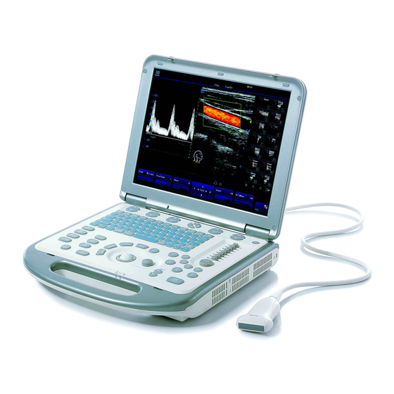
Page 30: System Introduction
System Introduction Introduction of Each Unit... - Page 31 System Introduction Name Function Monitor Displays the images and parameters during scanning Control panel Operator-system interface or control Handle Used for carrying the system Connects a transducer to the main unit; or connects a probe Transducer port extend module Transducer locking Locks or unlocks the transducer connected with the main unit lever...
-
Page 32: Extend Modules
System Introduction Extend Modules There are four extend modules available for the system: Probe extend module IO extend module V/A extend module ECG module 4.2.1 Probe Extend Module <1> <2> Name Function <1> Connector Connects to the transducer port of the main unit <2>... - Page 33 System Introduction 4.2.2 IO Extend Module Name & Symbol Function 1 & 2 Connects USB devices. USB port Connects a display or projector VGA output port Connects serial port devices Serial port 5 & 6 Used for audio signals of D mode sound from Audio output port DVD output or audio comments Reserved...
- Page 34 System Introduction 4.2.3 V/A Extend Module The module is connected to the USB port of the main unit via a USB cable. < > < > < > < > Name Function Audio input port Used for audio signal input Audio input port Used for audio signal input Composite video input port...
-
Page 35: Control Panel
System Introduction Control Panel... - Page 36 System Introduction English Name Function Name Description soft menu Press to select the soft menu items displayed on controls 1 the bottom of the screen. Refer to the subsequent contents for specific functions. soft menu Press to select the soft menu items displayed on controls 2 the bottom of the screen.
- Page 37 System Introduction English Name Function Name Description iStation Press to enter or exit the patient information management system. User-defined key You can assign a function to the key. User-defined key You can assign a function to the key. User-defined key You can assign a function to the key. User-defined key You can assign a function to the key.
- Page 38 System Introduction English Name Function Name Description Back Return or delete Press to return to the previous operation or delete the previous item. Change Change Press to toggle between calipers within the same measurement. Measure Measure Press to enter or exit the application measurement mode.
- Page 39 System Introduction English Name Function Name Description Depth Depth Press to increase or decrease the imaging depth. Freeze Freeze Press to freeze or unfreeze onscreen image. Indicator 1 Indicates if the main unit is connected to the power supply. When the main unit is not connected to the power supply, the indicator light is off.
-
Page 40: Symbols
System Introduction Symbols This system uses the symbols listed in the following table, and their meanings are explained as well. Refer to “Safety Precautions” for safety symbols. Symbol Meaning Type-BF device Refer to relevant content in the Operator’s Manual, to avoid safety accidents Dangerous voltage No user serviceable parts (applied to the power adapter) - Page 41 System Introduction Symbol Meaning Pencil probe port (reserved for future use) Product serial number Manufacture date Manufacturer Authorized representative in the European Community This product is provided with a CE marking in accordance with the regulations stated in Council Directive 93 / 42 / EEC concerning Medical Devices.
-
Page 42: Set-Up & Connections
Set-up & Connections System Set-up Please read and understand the safety precautions before placing the system. Turn off the power and disconnect the system from all peripherals. Carry the system by holding the handle. Place the system in a desired location. Leave at least 20cm at the back and both sides of the system. -
Page 43: Connecting / Disconnecting A Transducer
When connecting or disconnecting a transducer, place it in a proper position, to prevent the transducer from falling off or becoming damaged. Only use the transducers provided by Mindray. Aftermarket transducers may result in damage or cause a fire. 5.3.1 Connecting a Transducer... -
Page 44: Connecting The Probe Extend Module
Set-up & Connections 5.3.2 Disconnecting a Transducer To disconnect a transducer: Toggle the locking lever to the bottom position to unlock the connector of the transducer. Pull the transducer connector straight out, as shown in the figure below. Connecting the Probe Extend Module Connect the probe extend module to the main unit via the transducer port, thus the transducer port is extended to two usable ports and one docking port. -
Page 45: Connecting Io Extend Module
Set-up & Connections Connecting IO Extend Module Connect the IO extend module to the main unit via the IO extend port, thus the data port is extended to two or more. See the following figure. IO extend module Connecting the V/A Extend Module Connect the V/A extend port module to the main unit via a USB port. -
Page 46: Connecting The Footswitch
Set-up & Connections Connecting the Footswitch Connect the footswitch to the main unit via a USB port. See the following figure. You can set the functions of the footswitch in the [Key Config] page. Refer to the section 17.2 for footswitch setup. Connecting / Removing a USB Memory Device DO NOT directly remove a USB memory device;... -
Page 47: Installing A Graph / Text Printer
Set-up & Connections 5.10 Installing a Graph / Text Printer As shown in the figure below, a graph / text printer has a power cord and data cable. The power cord shall be directly connected to a wall receptacle as required. Power cord Data cable USB connector... -
Page 48: Installing A Video Printer
Set-up & Connections 5.11 Installing a Video Printer The video printers supported by the system include analog video printers and digital video printers. The video printers, whether analog or digital, consist of B / W printers and color printers. To connect an analog video printer (SONY UP-897MD for example), the procedure is as follows (the methods for B / W printers and color printers are the same): Unpack the printer. - Page 49 Set-up & Connections Data cable Remote cable Power cord To connect a digital video printer (MITSUBISHI P93DC for example): Unpack the printer. Place the printer in the proper position. Connect the power cord of the printer to a receptacle. Use a USB cable to connect between the USB port of the system and the USB port of the printer.
-
Page 50: Use Of The Drawbar Case
Set-up & Connections Click [Return] to make the settings to take effect. Press the [Print] key on the control panel to print. USB cable Power cord Please refer to the accompanying manuals of the printers for more details. 5.12 Use of the Drawbar Case The drawbar case is used for storage and transportation of the system and some options. - Page 51 Set-up & Connections Remove the drawbar, and turn around the case and place it on the flat surface, and finally open the case. Note: To open the case, first you have to unlock the three locks at the front and at one side of the case.
-
Page 52: Use Of M-Pack
Set-up & Connections 5.13 Use of M-Pack 5.13.1 Introduction of M-Pack M-Pack is a portable pack, which is used when you carry it on your shoulders to hold the system and simultaneously operate the system. NOTE: When using M-Pack, you shall avoid operating and walking at the same time to prevent tumble caused by blocked line of sight or distraction. - Page 53 Set-up & Connections <1> <2> <4> <3> <5> <6> <7> Name Function <1> Accessory Bag Holds transducer and ultrasound gel, etc. <2> Upper Cover Holds and fixes the display of the system <3> Platform Holds and fixes the control panel of the system. <4>...
- Page 54 Set-up & Connections <2> <3> <1> <4> Name <1> Display <2> Clips of the display <3> Fixing belt <4> Platform To fasten the M-Pack on the shoulders of the operator: Buckle up one end of one sling to the snap ring at the back of the platform, and buckle up the other sling as well.
- Page 55 Set-up & Connections After removing the transducer port cover and connecting the transducer, you are ready for operating the system. 5-14...
-
Page 56: Power On / Off
– immediately stop scanning. If the system continues to function improperly – fully shut down the system and contact Mindray Customer Service Department or sales representative. If you use the system in a persistent improperly functioning state – you may harm the patient or damage the equipment. - Page 57 If you find anything not functioning properly, this may indicate that the system is defective. In this case, shut down the system immediately and contact Mindray Customer Service Department or sales representative. NOTE: When you start the system or switch between transducers, you will...
-
Page 58: Powering Off The System
Power ON / OFF Powering OFF the System You need to follow the correct procedures to power off the system. In addition, after you upgrade the software or when the system is down, you need to power off and restart it. To power off your system normally: Gently press the power button once on the upper right corner of the control panel. -
Page 59: Basic Screen And Operation
Basic Screen and Operation Basic Screen The system monitor displays ultrasound images, parameters, menus and measurement results window. The following diagram maps out the different areas, such as patient information, image parameter & menu, image-in-image thumbnail, image area, thumbnail of images saved, body mark, help information &... - Page 60 Check [Gender], [Age] or [Operator] in the [Patient Info] box in the upper left corner of the screen. Manufacturer logo - The Mindray’s logo is displayed in the upper left corner of the screen. Hospital name - The name of your hospital is displayed on the screen, and can be entered through Setup →...
- Page 61 Basic Screen and Operation 7.1.2 Image Parameter and Menu Area The image parameter and menu are both displayed in this area. When no menu is available, this area displays the image parameters of the current mode. When an image menu is displayed, the imaging parameters will be covered by the menu. To show or hide the image menu, click [Menu] key on the control panel.
- Page 62 Basic Screen and Operation 7.1.5 Thumbnail Area of Images Saved This area displays the thumbnails of saved images for the current patient. 7.1.6 Body Mark Area In the body mark status, this area displays the available body marks. 7.1.7 Area of Help Information and Cursor Icon The help information area displays various help information or progress bar in the current status.
-
Page 63: Basic Operations Of Screens
Basic Screen and Operation items only when they are highlighted. The soft menu items vary depending on the menu. The menu navigation will cause the change of the soft menu, while the change of the soft menu will cause the menu navigation. The soft menu items are operated respectively through the five groups of soft menu controls <1>, <2>, <3>, <5>... - Page 64 Basic Screen and Operation Composition Description The title bar is used to give a description for the content and function Title Bar of the screen. For some screens, contents are distributed across several pages. Page Tab Use the selection pointer and [Set] key to open / close the available pages.
-
Page 65: Patient Information
Patient Information Although you can start scanning a patient without entering patient information, it is recommended to enter patient information before an examination is started. The system will set up a unique information database for each patient based on the patient information entered, so that information of one patient will not be confused with that of another patient. -
Page 66: Setting Patient Information Display
Patient Information Setting Patient Information Display To set the contents displayed in the fields of [Patient Info] screen: Press [Setup] key on the control panel to show the [Setup] menu. Click [System] item to open the [System] screen. Click [General] tab to open the [General] page. If [Gender], [Age] or [Operator] is checked, it will be displayed in the image banner. -
Page 67: Entering Patient Information
Patient Information Entering Patient Information To start a new patient exam, press [Info] key to open the [Patient Info] screen. See the figure below: General information Exam information Operating information Function buttons To input patient information: Open the [Patient Info] screen. Place the cursor into the specific box and press [Set] key. - Page 68 Patient Information Name You can directly enter patient name through the keyboard. Characters of A through Z and 0 through 9 and “.” are allowed. Gender You can select Male or Female for patient gender in the drop down menu. DOB (Date of Birth) and Age You can enter the birth date of a patient, and the system will automatically calculate the patient age and display it on the screen.
- Page 69 Patient Information The following are the parameters which can be entered. You can enter the date manually or through the calendar. LMP: After you enter LMP, the system will calculate and display GA and EDD. IVF: After you enter IVF, the system will calculate GA and EDD. BBT: After you enter BBT, the system will calculate GA and EDD.
- Page 70 Patient Information Operating Information Accession #: refers to exam number used in DICOM. Operator, Diagnostician & Ref. Physician: input names of Operator, Diagnostician & Ref. Physician. If a name has been inputted before, you can select it from the drop-down list. Comment: exam-specific explanation or remarks.
-
Page 71: Searching A Patient
Patient Information Searching a Patient Before searching a patient, the patient information shall be available in the ultrasound system or USB memory device. You need to enter the [iStation] screen to search the patient. To enter the [iStation] screen: Press the [iStation] key on the control panel; or Press the [Review] key on the control panel and click the [iStation] button in the screen;... -
Page 72: Worklist
Patient Information Worklist To import patient information from DICOM Worklist server: Install the DICOM package and set the Worklist server, Connect the DICOM Worklist server and verify the connection. Click in the Patient Info screen to open the Worklist screen. Query and import patient information from the DICOM Worklist server. - Page 73 Patient Information Click [Start Exam], the patient information is imported into the system and then an exam is started. Or Click [Transfer], the patient information is imported into the [Patient Info] screen and it is opened. After you edit the patient information in the [Patient Info] screen, select [OK] to start a new exam.
-
Page 74: Exam Types
Exam Types If the exam type is changed during a measurement, all CAUTION: measurement calipers on the image will be cleared. The data of general measurements will be lost, but the data of application measurements will be stored in the reports. Introduction of Exam Types The system can perform the following exam types: A-Abdomen - (Adult Abdomen) -
Page 75: Selecting Transducer And Exam Type
Exam Types FAST (Focused Abdominal Sonography For Trauma) MSK (Musculoskeletal) Nerve Neonatal-Head Misc 1 (Miscellaneous 1) Misc 2 (Miscellaneous 2) Misc 3 (Miscellaneous 3) User-defined Selecting Transducer and Exam Type Opening Select Probe & Exam Screen Method one is: Directly connect a transducer or connect a transducer via the Probe Extend Module. Press [Info] key on the control panel to open the Patient Info screen. -
Page 76: Setting Exam Types
Exam Types [Save]: To save the image parameters in the current image mode as presets, open the [Select Probe & Exam] screen and click [Save] button. A dialog box pops up to prompt you the operation will overwrite the current image parameters. You can select [OK] or [Cancel]. - Page 77 Exam Types The selection method is described as follows: To select a transducer, move the cursor onto the column and select the transducer model through the drop-down menu. On the right side of the screen, you can view the exam types supported by the current transducer.
- Page 78 Exam Types 9.3.2 Exam Configuration The Exam Config screen is shown as follows: After an exam type is selected, Click [Rename] to change the name of the user-defined exam type, Click [Copy] to copy the parameters of the selected exam type. Select a second exam and, click [Paste] to paste the copied parameters to the secondly-selected exam type.
- Page 79 Exam Types 9.3.3 User-defined Exam Types To define exam types for a transducer: Press [Setup] key on the control panel to show the [Setup] menu. Click [Exam Preset] item to open the [Exam Preset] screen. Click [Exam Config] tab to open [Exam Config] page. Click to select [User-defined 1] in the [Exam Mode] area.
-
Page 80: Image Modes
Image Modes The images displayed in this system are only reference for WARNING: diagnosis. Mindray is not responsible for the correctness of diagnostic results. It is the responsibility of the clinician, who performs the exam, to capture the correct diagnostic results. -
Page 81: Switching Between Image Modes
Image Modes 10.2 Switching Between Image Modes Select and Switch B Mode control: press to enter the B Mode M Mode control: press to enter the M Mode Pulsed Wave Doppler control: press to enter the PW Doppler mode Continuous Wave Doppler control: press to enter the CW Doppler mode Color Mode control: press to enter Color Mode Power Mode control: press to enter Power Mode Dual-split display key: press to enter the Dual-split display mode. -
Page 82: Image Adjustments
Image Modes 10.3 Image Adjustments Imaging adjustments are performed through the following methods: Adjustments through image menus or soft menus The image menus are located on the upper left corner of the screen. To adjust: Press [Set] or [Back] key; or Rotate the [Multifunction] knob. - Page 83 Image Modes parameters are displayed while the image menu is not available. Roll the trackball to move the cursor onto a parameter, A frame appears around it; Press [Set] and the cursor disappears; Rotate the [Multifunction] knob to change the parameter; Press [Set] again to confirm.
- Page 84 Image Modes Acoustic Power The acoustic power refers to ultrasound power transmitted from the transducer. You should perform exams according to actual situation and ALARA Principle. Click [A. Power] item in the menu to select among percentages. The AP value is also displayed at the top of the screen. Trapezoid To turn on / off Trapezoid, click [Trapezoid] item in the menu.
- Page 85 Image Modes Select among Dark, Gray, Bright, Brighter and Brightest. Gain To adjust the overall B Mode image gain: Rotate the [iTouch] key located on the right side of the control panel. The gain value is displayed on the image parameter area, e.g. G70. Time Gain Compensation is used to adjust or compensate depth gain to different segments of the image.
- Page 86 Image Modes Select among maps 1 through 8. You can set the gray map in the image preset. Line Density Click [Line Density] item in the menu. Select between Low and High. Note: Changing Line Density will change B Mode frame rate (higher line density / lower frame rate, lower line density / higher frame rate).
- Page 87 Image Modes This feature rejects B Mode image noise, thus increasing signal-noise ratio. Post Process Post processing is used to apply modifications to a gray map in order to optimize overall image quality. Select [Curve], [Rejection] or [γ] from the B Mode menu. The post processing feature is valid for images in real time, freeze or cine review status.
- Page 88 Image Modes Move the cursor onto the ▲ marker. The cursor becomes a . Press the [Set] key and roll the trackball to move the ▲ marker along the horizontal axis. You will notice the B Mode image changes at the same time showing the modifications in real-time. After the adjustment is complete, press the [Set] key a second time to fix the marker in the new position.
- Page 89 Image Modes Speed This function is used to increase or decrease the M Mode sweep speed. Click [Speed] item in the menu. Change the speed value. The smaller the value, the quicker the refresh speed; the greater the value, the slower the refresh speed. Acoustic Power The acoustic power refers to ultrasound power transmitted from the transducer.
- Page 90 Image Modes Dynamic Range The Dynamic Range function is used to adjust contrast resolution of the B Mode image to compress or expand the gray display range. Click [Dynamic Range] item in the menu. Select a Dynamic Range value. The value is also displayed in the image parameter area, e.g. DR 70. IP (Image Processing) Image Processing is a combination of image parameters, and the system has 8 IP preset combinations.
- Page 91 Image Modes The transducer frequency is also displayed in the image parameter area in the upper left corner of the screen. RoI box position and size adjustment Hide the Color image menu. When the RoI box is dotted line, you can roll the trackball to change its position. Press [Set] to fix it in the new position and the RoI box turns to solid line.
- Page 92 Image Modes The gain value is displayed on the image parameter area. Flow State Click [Flow State] item in the menu. Select [Flow State] among L, M and H. Steer The Steer feature is used to adjust the RoI of color flow with different angles but with immobility of the linear transducer.
- Page 93 Image Modes This feature indicates the display effect of color image. Click [Map] item in the menu. Select among 1 through 11. The Color bar is changed with the Map value change. Wall Filter This feature is used to filter the speed signals of the low speed flow. Click [Wall Filter] item in the menu.
- Page 94 Image Modes 10.3.4 Power / DirPower Mode Fundamental Power Mode is a non-directionally display of blood flow in the form of intensity as opposed to flow velocity. DirPower (Directional Power Mode) provides the additional information of flow direction towards or away from the transducer. The adjustable parameters of Power Mode are consistent with those of the Color Mode.
- Page 95 Image Modes such as iTouch, SV, steer, Duplex, Triplex and HPRF, are not available in the CW mode. iTouch After you press the [iTouch] key on the control panel, the system will automatically set the PW baseline and PRF value to the optimum settings according to the current scanned tissue characteristics.
- Page 96 Image Modes Angle The angle between Doppler vector and flow is calculated to evaluate the flow speed. Click [Angle] item in the menu, and select [Angle] among values; or Rotate the [Multifunction] knob to change it. Quick Angle Click [Quick Angle] item in the menu. Change [Quick Angle] values in increments of 60°.
- Page 97 Image Modes Select a Dynamic Range value. Audio Click [Audio] in the menu. Change volume value of Doppler. Trace Sensitivity Click [Trace Sensitivity] in the menu. Select [Trace Sensitivity] value. Speed Click [Speed] in the menu. Select [Speed] value. Acoustic Power The acoustic power refers to ultrasound power transmitted from the transducer.
- Page 98 Image Modes Click [Auto Spectrum Calculation] to check the parameters for auto calculation in the screen; Click [Caliper] key to perform measurements; The results of auto spectrum calculation are displayed in the result window. Note: The result of auto calculation always displays at the top line of the result window, and will not disappear after new measurement calipers are added.
- Page 99 Image Modes Trace Area Click it in the menu to set up trace area for calculating Doppler waveform. It can be used in both real time and freeze statuses. To set it to Above, the area above the baseline is used for calculating Doppler waveform.
-
Page 100: Image Parameter Preset
Image Modes 10.3.7 iZoom (Full-screen Zooming) iZoom is used to magnify the area including the image area, parameter area and image banner in full screen. Method: (1) User-defined key setting: a) Open Key Config page via “[Setup]→ [System Preset]→ [Key Config]” b) Select a function-free key in the Function list. - Page 101 Image Modes The [A-Abdomen - All Probe] field on left side of the screen displays the parameter setup for all transducers in A-Abdomen exam type. The [A-Abdomen - 3C5s] field on the right side of the screen displays parameter setup for the 3C5s transducer in A-Abdomen exam type.
- Page 102 Image Modes B Gray Map and THI Gray Map Click [B Gray Map] or [THI Gray Map] on the left field to enter the settings of gray map, as shown in the figure below. Refer to the relevant B Mode chapter for adjustment of post processing curves. The system can store 8 different post processing maps, which are selectable through the image menu.
-
Page 103: Special Imaging Modes
Special Imaging Modes The system supports the optional imaging modes as follows: Smart3D imaging iScape panoramic imaging NOTE: The ultrasound images, specially obtained in the Smart3D mode or iScape mode, are provided for reference only, not for confirming a diagnosis. Please use caution to avoid misdiagnosis. - Page 104 Special Imaging Modes Recommended: Cephalic face up (figure a) or face aside (figure b); NOT recommended: Cephalic face down (figure c). c) Amniotic fluid(AF) isolation The region desired is isolated by amniotic fluid adequately The region to imaging is not covered by limbs or umbilical cord. d) The fetus keeps still.
- Page 105 Special Imaging Modes Procedures for 3D Imaging 11.1.1.2 Basic Basic procedures for 3D imaging are as follows: 1. Select the proper exam mode and preset the 3D data. 2. Optimizing the 2D image and setting ROI (Region Of Interest). 3. Capturing 3D images. 4.
- Page 106 Special Imaging Modes Functions of the parameters are described in the following table. Parameter Description Method Value: Linear/ Fan Refer to “11.1.4.1 Method” for details. Distance(mm) Width of linear scanning. Angle(deg) Angle of fan scanning. Window Mode Value: Four/ One When One is selected, only 3D image displays.
- Page 107 Special Imaging Modes Parameter Description Grad. Light (%) The greater the value is, the more stereoscopic the 3D image appears. Available only in Surface rendering mode. Set menu and soft menu items To set displayed menu and soft menu items in Image Capture, 3D Review and Reset ROI, refer to section 17.8 for details.
- Page 108 Special Imaging Modes Sector scanning Rotate the transducer once from the left to the right side (or from the right to the left) to involve the whole region desired. See the following figure. 11.1.4.2 Procedures The following takes the fetal face 3D imaging as an example. 1.
- Page 109 Special Imaging Modes A small ROI results in an incomplete 3D image, which can be corrected by Resetting ROI after collection. Refer to “11.1.6 Reset ROI” for details. 3. Press the [Update] key or use the soft menu control to click [Start Capture] to start the capture.
- Page 110 Special Imaging Modes Soft menu displays at the bottom of the screen is as shown in the following figure. Use the Multifunctional button to active the desired row of the soft menu and adjust the parameters. Set the Review Window Press the [Quad] key on the control panel to switch between a single-window and multi-window display format of 3D images.
- Page 111 Special Imaging Modes NOTE: Position of the fetal face 3D image in the D window is not the actual posture of the real fetal, it inverses.In the figure above, the actual fetal posture is head down (orientating the mother’s feet), but the 3D image appears head up. Scanning plane and the transducer movement Arrow in the figure below indicates the movement of the transducer, (you can move the transducer in the contrary direction of the arrow.)
- Page 112 Special Imaging Modes Section A Section B Section C E.g. select A as the current window and roll the trackball, section lines (indicate the position of A) in the B and C window move, and image in A window changes. NOTE: 1.
- Page 113 Special Imaging Modes 11.1.5.3 Adjusting Parameters In 3D image browsing status, you can adjust the rendering, colorize, smooth and other parameters via 3D view menu and soft menu to optimize the image. See “11.1.2 Smart3D Presetting” for detailed parameter descriptions. 11-11...
- Page 114 Special Imaging Modes 11.1.5.4 Rotating Image The system supports the following rotation modes: Sphere center Rotation Axial rotation Auto Rotation Sphere center rotation Rotate the 3D image around the center point of the 3D image.The procedures are as follows: 1. Set the 3D window as the current window. Click [Current Window] to set it to [D], or, you can press the Multifunctional button to display the cursor and click the D window.
- Page 115 Special Imaging Modes 11.1.5.5 Zooming Image Method for Zoom Press the [Zoom] key to enter the image magnification status; Rotate the [Multifunction] knob to increase or decrease the magnification factor. The maximum zooming factor is 4. Correlation between 3D image and planes in Zoom status When the 3D image is zoomed in or out, the planes is changed along with it.
-
Page 116: Iscape
Special Imaging Modes 11.1.7 Save and Open Images 1. In the 3D Review mode, press the [Save] key (with user-defined saving function) to save the current image to the patient information management system in the set format and (JPG or BMP) and image size, which you set via [Setup] [System] [General] [Storage]. - Page 117 Special Imaging Modes The setting path is “Setup → System → Key Config”. Refer to section 17.2 for details. Press the user-defined iScape panoramic imaging key to quickly enter the mode. To exit iScape mode: If in the capture status, click [Exit] in the menu; or press the [Esc] key. If in the review status, press [Esc] to exit to the capture status, and then press [Esc] again to exit iScape mode.
- Page 118 Special Imaging Modes 11.2.3 Capture Images To enter the iScape capture mode: Move the cursor onto the [iScape] item in the Other menu and press the [Set] key; Press the user-defined iScape panoramic imaging key on the control panel. Press the [Update] key or use the soft menu control to click [Start iScape] to start the iScape image capture.
- Page 119 Special Imaging Modes Evaluate image quality Many variables may affect the overall image quality. It is important to evaluate the image content and quality before an image is used for diagnosis or measurements. NOTE: iScape panoramic imaging is intended for well-trained ultrasound operators or physicians.
- Page 120 Special Imaging Modes 11.2.6 Save and Open Images In the mode for reviewing an extended image, Press [Save] key (with user-defined saving function) to save the extended image to the default position, in the format FRM (Single-frame images can be transformed to PC format: JPG, BMP or DCM files.
-
Page 121: Cine Review
Cine Review After you press the [Freeze] key, the system allows you to review and edit the images prior to the image frozen. This function is called as cine review. The magnified images can also be reviewed after the [Freeze] key is pressed, and the operating method is the same. You can change post processing maps, perform measurements, add comments and body marks on the images being reviewed. -
Page 122: Cine Review In The B Or C Mode
Cine Review 12.2 Cine Review in the B or C Mode 12.2.1 Manual Cine Review After the cine review is entered in the B or C mode, rolling the trackball will display the cine images on the screen one by one. If you roll the trackball to the left, the review sequence is reversed to the image-storing sequence, thus the images are displayed in descending order. -
Page 123: Linked Cine Review
Cine Review To switch between Auto Cine and Manual Cine, the method is identical to that of the B or C mode. 12.4 Linked Cine Review In dual live status, the linked cine review refers to review of the images captured at the same moment. -
Page 124: Saving Cine
Cine Review Method 2 Manually return images to the first image to be reviewed, and press the [Menu] key to open the cine menu, and click [Set First Frame] to set the start position. Press the [Menu] key to close the cine menu, and the system returns to the cine review status. - Page 125 Cine Review 12.7.2 Setting Cine Memory Split You can set the cine memory split through the path Setup → System → Image Preset. Select Auto or Split for Cine Memory in the Image Preset page. “Auto” for the cine memory indicates the system splits the cine memory as per the number of B image windows;...
-
Page 126: Measurements
Measurements Be sure to measure areas of interest from the most WARNING: optimal image plane to avoid misdiagnosis from inaccurate measurement values. To obtain accurate Doppler flow measurement values, maintain an optimal 60º angle to the vessel. Doppler angles over or less than 60º will produce false readings and potential misdiagnosis. -
Page 127: General Measurements
Measurements 13.1.2 Measurement Result and Help Information The system displays and updates measurement results in the result display area. The Help information concerning measurement and calculation is displayed in the Help bar at the bottom of the screen. 13.2 General Measurements 13.2.1 General Measurements –... -
Page 128: Application Measurements
Measurements 13.2.3 General Measurements - Doppler General measurements in the D mode are also called “Doppler measurements.” The measurement tools are as follows. Measurement tool Function Time The time interval between any two points. Heart rate N intervals (n≤8) are measured to calculate a PW Mode derived HR value in Beats Per Minute (BPM). -
Page 129: Comments (Annotations)
Comments (Annotations) You must ensure that the entered comments are correct. WARNING: Incorrect comments may cause misdiagnosis! Comments can be added to an ultrasound image to bring to attention, notate or communicate information observed during the examination. You can add comments to: zoomed image cine review image real-time image... -
Page 130: Comment Menu
Comments (Annotations) 14.2 Comment Menu 14.2.1 Comment Text Library Menu After entering the comment status, pressing the [Menu] key will show or hide the Comment Text Library menu. From these menus, you can add comment texts selected from the menu items. -
Page 131: Adding Comments
Comments (Annotations) add the comment text to the specified location. Click [Home] in the menu to make the cursor to return to the set home location. Changing Font Size/Arrow Size To change font size of comment text, click [Font Size] to select among Small, Middle and Large. -
Page 132: Moving Comments
Comments (Annotations) Or press [Menu] key, and the comment text library menu of the current exam mode will be displayed on the left side of the screen. You can navigate to the comment text library menus for other exam modes. To select the comment text: Move the cursor onto the desired comment text on the menu and press [Set], and then the system adds the selected comment text on the set location. -
Page 133: Modifying (Editing) Comments
Comments (Annotations) 14.5 Modifying (Editing) Comments 14.5.1 Modifying (Editing) Characters Move the cursor on the comment that needs to be modified, and press the [Set] key to select it. Press the [Set] key again to enter the edit status. Use the key to move the cursor to a location where needs to insert characters, and type characters or select the new comment text from the comment text library menu. -
Page 134: Deleting Comments
Comments (Annotations) 14.6 Deleting Comments 14.6.1 Deleting Comment Characters, Texts or Arrows Move the cursor to a position where you need to delete the comment, whether a character, a text or an arrow. Press the [Set] key to select the comment to delete. Press the [Del] or [Back] key to complete the deleting operation, and the cursor turns to the comment cursor. - Page 135 Comments (Annotations) 14.7.2 User-defined Comments You can customize user-defined comments for an exam mode according to your preferences. The customized comments will display in the corresponding exam mode. The operational steps are as follows: To open the [Comment Preset] screen, select Comment Preset in the Setup menu. The following example is comment preset in A-Abdomen mode.
- Page 136 Comments (Annotations) Select Available Items: First select a comment library in the drop-down list beside “Available Items”, and then click [Set] on one item displayed below “Available Items”. Click to add one item to the box on the right side. To add all items on the left side to the right side, click Change the selected items on the right side: select an item on the right side box and click [Up], [Down], [Left] or [Right] button to move the position of the item.
- Page 137 Comments (Annotations) After you customize comments, click [OK] to confirm and exit the [Comment Preset] screen. 14-9...
-
Page 138: Body Marks (Pictograms)
Body Marks (Pictograms) The Body Mark (Pictogram) feature is used for indicating the exam position of the patient and transducer position and orientation. 15.1 Entering / Exiting Body Mark Mode To enter the Body Mark status: Press to enter the body mark selection status. To exit the Body Mark status: Press [Body Mark] again to exit the body mark status;... -
Page 139: Adding Body Marks
Body Marks (Pictograms) 15.4 Adding Body Marks The following will describe the steps to add the first Body Mark graphic to the imaging window. Enter the Body Mark status; use the soft menu control to click [Library] to select the body mark category. -
Page 140: Deleting Body Marks
Body Marks (Pictograms) Roll the trackball to move the Body Mark graphic to the desired position. Click the [Set] key to anchor and confirm the new graphic position. NOTE: In Dual B Mode, a Body Mark cannot be moved between the separate image windows. - Page 141 Body Marks (Pictograms) Preset Exam Type Body Mark Preferences Select the [Body Mark Preset] item in the Setup menu and enter the [Body Mark Preset] screen (as shown in the figure below). Select the exam type that you will preset the Body Mark presets from Exam Mode drop down menu.
- Page 142 Body Marks (Pictograms) In the body mark preset screen above, click to enter the user-defined body mark screen (as shown in the figure below). Note: You can edit, delete, or export a user-defined graphic. In addition, you can create a Body Mark graphic with a draw tool or add it from loading.
- Page 143 Body Marks (Pictograms) To add user-defined body marks: Click the [Add] button on the screen to enter the creation selection screen of Body Mark. You can select to copy an existing body mark or draw a new graphic. Select a body mark on the current screen and click [Copy] to enter the body mark drawing screen, thus you can edit the copied body mark.
- Page 144 Body Marks (Pictograms) specialized graphic. Brush Eraser Up/down flip Left/right flip Zoom in Zoom out Rotate Drag You can select on the screen, to adjust position of the transducer indicator on the body mark and rotate the [Multifunction] knob to change direction of the indicator. After the drawing of a body mark is complete, click [OK] to save it and exit the user-defined body mark status.
-
Page 145: Patient File Management
Patient File Management 16.1 Image File Formats The system supports file formats which belong to the system and file formats which are PC-compatible. The file formats which belong to the system include: Single-frame image file (FRM) System-defined single-frame static file format, non-compressed format, used for measurements and comments. -
Page 146: Memory Media
Patient File Management 16.2 Memory Media The memory media include: System hard disk USB memory devices: USB flash drive, removable USB hard disk, DVD-RW DICOM memory VCR or DVR recorder 16.3 Storing Image Files During the process of examining a patient, you can directly store the exam images to the patient database for image review. - Page 147 Patient File Management 16.3.2 Quickly Saving Images to USB Flash Drive Use the user-defined key on the control panel to quickly save single-frame image or cine images to a USB flash drive. The files are saved under directory of patient/exam of US Export in the USB flash drive.
- Page 148 Patient File Management default filename. The thumbnail of this image will appear in the thumbnail area on the right side of the screen. When you move the cursor onto the thumbnail, its filename with suffix will be displayed. When a dialog box is displayed on the current screen, press the shortcut key to save the screen of the screen in the JPG or BMP format (can be selected in preset).
-
Page 149: Storage And Management Of An Exam Report
Patient File Management 16.4 Storage and Management of an Exam Report Storing a Report The patient exam report is automatically stored in the exam of the patient directory. Importing, Exporting and Sending a Report In the [iStation] screen, select patient data, click [Import] or [Export] to import or export patient information, images and reports from or to an external memory device. -
Page 150: Istation - Patient Data Management
Patient File Management To export the report to specified location: Check [Export Report]. Select report format in the drop-down list. Click [OK] to confirm. To preset paper size, the path is: Setup → System → General →Exam Report. You can select among A4, B5 and Letter. - Page 151 Patient File Management Searching a Patient Select the data source of patient database, i.e. find where the system stores the patient data by default. Set criteria: Enter a keyword, or select among ID, Name, DOB and Exam Date. The system searches and displays the result in the patient data area. To continue to search in the result, check [Find in Result] item.
-
Page 152: Image Review And Analysis
Patient File Management or send it to the video printer connected with the system. Deleting Patient Data To delete the selected patient or exam data, click the [Delete] button on the right side of the screen. However, you can neither delete patient data being printed, exported or sent, nor delete the current exam. - Page 153 Patient File Management 16.6.1 Image Review You can review all images stored in one exam, and send, delete or analyze the stored images. After the images of the current exam are stored, the thumbnails of the images are displayed on the right side of the screen, and you can review them through the thumbnails.
- Page 154 Patient File Management screen will display the selected patients in the [iStation] screen; if no patient is selected, the Review will display all patients in the patient database, and the exam of the current patient is in the expansion status. [Info]: press to review or edit the currently-selected patient information.
-
Page 155: Ivision
Patient File Management 16.7 iVision iVision function is used for demonstration of the images stored. Image files are played according to file names one by one. To open [iVision] screen: Press [Menu] key on the control panel. Navigate to the Other menu. Click iVision item in the Other menu. -
Page 156: Sending Image File
Patient File Management The time interval between images played is same and can be changed. It is set to 5s by default. Manual demonstration: the image files are manually played starting from the start or the end. The image files are played in reversed directions by pressing , and they cannot be played cyclically. -
Page 157: Print Job Management
Patient File Management The [Send To] screen is as follows: For external memory device (e.g. USB memory devices) or DVD-RW, you can select storage format: PC Format (a single-frame image is exported as JPG or BMP; cine is exported as AVI); DICOM (single-frame DCM and multi-frame DCM). When an image is sent to an external medium, the system will automatically create a filefolder, and name it in the form of patient name + patient ID. -
Page 158: Backing Up Files Through Dvd-Rw
Patient File Management Information of all print jobs is displayed in the list, including ID, name, status (being printing or suspended), and submit time. To delete a print job: Click to select a print job in the list. Click [Delete] button. To restart a print job after it is suspended: Click to select a suspended print job in the list. - Page 159 Patient File Management To write data to a CD/DVD: Put a CD/DVD in the tray; Click [Send To] or [Export] button in the screen (such as the [iStation] screen); Click [OK] or [Export] button in the file-exporting screen; After the writing process is complete, the system automatically ejects the CD/DVD if the format is ISO.
-
Page 160: Reviewing The Avi Files
Patient File Management During the backup process, if a CD/DVD is forcibly CAUTION: taken out or you perform other operations, the backup process will fail or the system may malfunction. You must press [Eject Disc] button to take out the DVD disk before disconnecting the DVD-writer or turning off the system. -
Page 161: Parameter Setup
CD or USB memory devices. When the setup data is changed, be sure to save the CAUTION: preferences according to the methods described in this chapter. Mindray is not responsible for the loss of the setup data. 17.1 Entering / Exiting Setup To enter the setup status: Press the [Setup] key on the control panel;... -
Page 162: System Setup
Parameter Setup 17.2 System Setup The system setup contains several pages, i.e., Region, General, Image Preset, Meas, OB, Key Config, Biopsy and Option. To confirm the modified parameters, click [OK]. To cancel the modified parameters, click [Cancel]. Click the [Load Factory] button to restore the current page to the factory settings. The content of each page is described as follows. - Page 163 Parameter Setup To define [Print] or [Save] key: Select [Key] tab to open the [Key] page. See the figure below. Click to select [Print] or [Save]. Click to select a function in the [Output] page. Click [OK]. To define [F1] through [F4] keys: Select [Key] tab to open the [Key] page.
-
Page 164: Exam Mode Preset
Parameter Setup Click to select [F1], [F2], [F3] or [F4]. Click to select a function in the [Output], [Advanced Features], [Measurement] or [Other] page. Click [OK]. To define footswitch: Select [Footswitch] tab to open the [Footswitch] page. See the figure below. Click to select [Left] or [Right]. -
Page 165: Comment Preset
Parameter Setup 17.5 Comment Preset Refer to “14.7 Comment Preset”. 17.6 Body Mark Preset Refer to “15.8 Body Mark Preset”. 17.7 Measurement Preset Refer to Measurement Preset in the Operator’s Manual [Advanced Volume]. 17.8 Key and Menu Preset You can preset parameter items in image modes for all types of transducers, in the menu (displayed at the bottom of the screen) and the menu (displayed on the upper left side of the screen), as well as parameter items for 3D capture, 3D review, PW mark, Reset ROI. - Page 166 Parameter Setup Available Items on the left side: You can select these items and move them to the Softkey page the right side. Items in the Softkey page on the right side: These items will display in the menu. Delete items from the soft menu To delete one item: Move the cursor onto an item in Softkey page on the right side, which is highlighted, click [Set], and then move the cursor onto and click [Set].
- Page 167 Parameter Setup You can click [Up], [Down], [Left] or [Right] buttons to change position of an item. For example, to move an item down, Select an item, Click [Down] The item will move down, and the item below it will move up. 2....
-
Page 168: Peripheral Setup
Parameter Setup the image menu. Change position of an item To change position of an item, select the item in the right side box and click [Move Up] or [Move Down]. Exit the [Key and Menu Preset] screen Click [OK] to confirm the preset operations and exit the screen; Click [Cancel] to cancel the preset operations and exit the screen. - Page 169 Parameter Setup After the installation is complete, you need to set the printer in the [Peripheral Config] screen. 2. Set a Printer To set a default graph / text printer, select a graph / text printer in the list and click [Set Graph/Text].
- Page 170 Parameter Setup DVR Settings Settings Available Selections Svideo Input Channel CVBS Output Mode NTSC HQ (1 hr.): high quality; one hour recorded for a disc SP (2 hr.): standard play; two hours recorded for a disc Record Quality EP (4 hr.): extended play, equivalent to VHS; four hours recorded for a disc LP (6 hr.): long play, equivalent to VHS;...
-
Page 171: Manage Settings
17.11 Maintenance The [Maintenance] item is designed for you to update the system software or other special functions. If you require these functions, please contact Mindray Customer Service Department or sales representative. 17.12 System Information Select the [About] item in the Setup menu to enter the system information screen, which displays the system software version and versions of other devices. - Page 172 Parameter Setup configurations and version. To export the system information, click [Save] in the [System Information] page, specify the file name and file path, you can save the information to a txt file. 17-12...
-
Page 173: Biopsy Guide
Biopsy Guide 18.1 Entering or Exiting Biopsy Menu To enter the biopsy: Press the [Biopsy] key on the control panel, and the screen displays “Please verify guidelines before biopsy”. Click [OK] to show the biopsy guide line. Press the [Menu] key to show the image menu, and move the cursor onto the menu title and click Biopsy in the pop-up menu. -
Page 174: Verifying The Biopsy Guide Line
Biopsy Guide 18.3 Verifying the Biopsy Guide Line Prior to each biopsy procedure, be sure to verify the WARNING: guide line. If the needle is not consistent with the guide line, do not perform the biopsy procedure. NOTE: The B-Mode image must be live and active to verify the onscreen biopsy guideline. -
Page 175: Ecg
The system can be configured with the optional ECG module. In that case, the ECG signal is displayed on the image, and can be reviewed simultaneously with the image after the image is frozen. To avoid electric shock, the following checks shall be WARNING: performed prior to an operation: a) The ECG electrode cable shall not be cracked, frayed... -
Page 176: Ecg Connection
19.1 ECG Connection The ECG connection shall be performed in the following procedure: Turn off the power supply of the system, and connect the ECG module to the USB port of the system; Connect the ECG cable to the ECG port of the ECG module; Turn on the power supply of the system;... -
Page 177: Ecg Triggering
19.3 ECG Triggering 19.3.1 ECG Triggering ECG triggering means that image scanning is activated at some time points of ECG signals, thus obtaining B images at these time points. When ECG triggering occurs, some marks appear on the ECG waveform, indicating the time points when the B images are captured. -
Page 178: Setting Ecg
19.6 Setting ECG You can set up ECG parameters through the path: Setup → Image Preset → ECG page. See the figure below. 19-4... -
Page 179: Image Recording
Mindray is not responsible for any data loss. 20.1.1 Setup To set the following parameters before using VCR: The setting path is: Setup →... - Page 180 Image Recording To record: Connect the VCR recorder to the ultrasound system and put a cassette in the recorder. Set the VCR recorder through the following path: Setup → Peripheral → Recorder. Start the ultrasound exam and acquire images. Press the user-defined key (preset in the [Key Config] screen) on the control panel. Move the cursor onto the menu title to navigate to the VCR Record selection and press [Set] to show the VCR Record menu.
- Page 181 Image Recording The buttons at the bottom of the screen are used to control replay. Their functions are described as follows: Play Viss Mark; to add segment mark in the current position. Pause Search blank. Stop Stop VCR replay (but still in VCR replay mode) and eject the cassette.
-
Page 182: Dvr (Digital Video Recorder)
Image Recording 20.2 DVR (Digital Video Recorder) You can use the DVR recorder (Medical Video Recorder MVR-11) to record and replay videos and audios stored in DVD disc or hard disc. 20.2.1 Setup To set up DVR settings, the path is the Setup → Peripheral → Recorder → DVR Settings. Refer to “17.9 Peripheral Setup”... - Page 183 Image Recording 20.2.3 Record Recording is to record videos/audios obtained from the examination and to store them into DVD or hard disc of the DVR recorder. Preparation before recording Connect the DVR recorder to the ultrasound system and ensure the DVD disc is put in the tray and there is adequate storage capacity in the hard disc.
- Page 184 Image Recording Entering/Exiting To enter the DVR data management screen, click [Data Manage] in the [DVD Record] menu. To exit the DVR data management screen, click [Exit] button on the [DVD Data Manage] or [HDD Data Manage] screen. DVD Data Management DVD Data management contains title management and DVD disc management, as shown in the following figure.
- Page 185 Image Recording Click to export all data on the DVD to hard disc. HDD (Hard disc drive) Data Management HDD data management contains renaming, deleting or exporting of a single record. As shown in the following figure, the progress bar indicates the proportion of occupied storage to the whole storage with a record list on the left side.
- Page 186 Image Recording Image area Record list Entering/Exiting To enter the replay screen: Click [Record Media] in the [DVR Record] menu to select storage medium. Click [Video]. To exit the replay screen, click in the lower part of the replay window. Preparation before replay Connect the DVR recorder to the ultrasound system.
- Page 187 Image Recording Play Next segment Pause Open/Close tray Stop the replaying Exit the replay status Previous segment Sound Fast backward Mute Fast forward Adjust volume Search Title/Chapter: A chapter marker will be automatically inserted by the recorder each time when a record pauses.
-
Page 188: Batteries
Batteries 21.1 Overview The battery charges when the system is connected to the AC power supply. If the system is turned off; a completely discharged battery will fully charge in 2 to 3 hours; or generally a battery has been charged for 2 hours, it can restore the quantity of electric charge to above 95%. -
Page 189: Installing And Removing The Batteries
Batteries Do not leave the batteries in direct sunlight. The batteries are designed to be charged only in this system; charge the batteries only when the ambient temperature is between 0 and 40 ℃. Store the batteries out of the reach of children. When the batteries are out of power, please charge them immediately. -
Page 190: Battery Status Indicator
Batteries To install the batteries: Turn off the system, and disconnect the adapter from the main unit. Close the monitor, turn the system upside down and put it on the table. You can see two battery bays at the bottom of the system (Note that the batteries shall be put in correct direction;... -
Page 191: Checking Battery Performance
Batteries battery is stored in the shady and cool area with FCC (full current capacity). One Full Discharge / Charge Cycle Process is: Full discharge of the battery to let the system automatically shut down. Charge the system to 100% FCC (full current capacity). Discharge of the system for complete shutdown. -
Page 192: System Maintenance
Routine system maintenance shall be completed by the user. Service maintenance will be provided by Mindray service engineers while the system is under warranty. System maintenance after the warranty has expired is the full responsibility of the owner / operator. - Page 193 System Maintenance NOTE: Do not use hydrocarbon glass cleaner or cleaner for OA (Office Automation) equipment to clean the monitor. These substances may cause deterioration of the monitor. Cleaning the control panel, cover and bracket a) Use dry soft cloth to clean the surface of the system. If the system is dirty, moisten the soft cloth with a mild or neutral detergent and wipe off any stains.
-
Page 194: Maintenance Checks By Service Engineer
22.2 Maintenance Checks by Service Engineer The following checks must be performed to ensure and maintain system safety and performance. Please contact Mindray Customer Service Department or sales representative to schedule and carry out these checks. 22-3... -
Page 195: Consumables And Periodic Part Replacement
Image recording by using the standard transducer 22.3 Consumables and Periodic Part Replacement This system contains some consumables and parts requiring periodic replacement. Before replacing them, please contact Mindray Customer Service Department or sales representative for instructions. 22.4 Troubleshooting Do not spill water or other liquid into the system while CAUTION: you perform the cleaning. - Page 196 System Maintenance Troubleshooting Table Failure Cause Measure After the power supply is 1. Verify the system is Abnormal power system turned power plugged in. or incorrect connection of indicator does not light on. 2. Verify that the plug has the power cord. not become loosened or dislodged from the back of the system.
-
Page 197: Acoustic Output
Acoustic Output This section of the operator’s manual applies to the overall system including the main unit, transducers, accessories and peripherals. This section contains important safety information for operators of the device, pertaining to acoustic output and how to control patient exposure through use of the ALARA (as low as reasonably achievable) principle. -
Page 198: Alara Principle (As Low As Reasonably Achievable)
Acoustic Output 23.3 ALARA Principle (As Low As Reasonably Achievable) It is required to practice ALARA when using ultrasound energy. Practicing ALARA ensures that the total energy level is controlled below a low enough level at which bioeffects are not generated while diagnostic information is being accumulated. - Page 199 Acoustic Output MI (Mechanical Index): The mechanical bioeffects are the result of compression and decompression of insonated tissues with the formation of micro bubbles that may be referred to as cavitations. MI is an index that shows the possibility of the cavitations generation based on acoustic pressure, and the value in which the peak-rarefactional acoustic pressure is divided by the square root of the frequency.
-
Page 200: Acoustic Power Setting
Acoustic Output 23.4.2 MI/TI Display TI and MI values are displayed in real time in the upper part of the screen. The operator should monitor these index values during examinations and insure that exposure time and output values are maintained at the minimum amounts needed for effective diagnosis. Under different operating conditions, once there is a situation that a MI value is greater than 1.0, the start point of displaying MI values is 0.4. -
Page 201: Acoustic Power Control
Acoustic Output Default choices Initial power 10% to 100%* Definition of 100%: The maximum acoustic power of a transducer determined by the increase in transducer surface temperature in the selected mode and the acoustic power restrictions specified by the FDA. NOTE: This system automatically returns to the settings whenever changes are made to the values (when you turn on the power,... -
Page 202: Acoustic Output
Acoustic Output Mode. Acoustic attenuation of tissue is directly related to transducer frequency. The focal point is related to active aperture of transducer and beam width. For the higher PRF (pulse repetition frequency), the more output pulses occur over a period of time. Receiver Controls The receiver controls (for example, gain, dynamic range, and image post-processing, etc.) do not affect output. -
Page 203: Measurement Uncertainty
Acoustic Output parameters were developed as general indicators of risk from either thermal or mechanical action of the ultrasound wave. They serve to indicate to the operator whether a particular setting of the system increases or decreases the possibility of Thermal or Mechanical effect. More specifically, they were designed to assist in the implementation of the ALARA principle. -
Page 204: References For Acoustic Power And Safety
Acoustic Output 23.9 References for Acoustic Power and Safety “Bioeffects and Safety of Diagnostic Ultrasound” issued by AIUM in 1993 “Medical Ultrasound Safety” issued by AIUM in 1994 "Acoustic Output Measurement Standard for Diagnostic Ultrasound Equipment, Revision 3" issued by AIUM/NEMA in 2004 "Standard for real-time display of thermal and mechanical acoustic output indices on diagnostic ultrasound equipment, Revision 2"... -
Page 205: Measurement Accuracy
Measurement Accuracy Table 1 Error of Two-Dimensional Images Parameter Value range error Within + / - 3%; or when the measured Depth / Distance Maximum 300 mm value is less than 40 mm, the error is less than1.5 mm. Within + / - 7%; or when the measured Area (Trace) Maximum 1126 cm value is less than 16 cm... - Page 206 Measurement Accuracy Within the selected field range, the measurement accuracy is NOTE: ensured within the range mentioned above. The accuracy specifications are performance in the worst conditions, or based on the real test for the system, regardless of acoustic speed error. 24-2...
-
Page 207: Safety Classification
Safety Classification According to the type of protection against electric shock: a. CLASS I EQUIPMENT According to the degree of protection against electric shock: a. TYPE-BF EQUIPMENT According to the degree of protection against harmful ingress of water: a. The main unit belongs to IPX0, and the transducers belong to IPX7. b. -
Page 208: Guidance And Manufacturer's Declaration
Guidance and Manufacturer's Declaration The system complies with the EMC standard IEC60601-1-2: 2001+A1:2004. The use of unapproved accessories may diminish system WARNING: performance. NOTE: Use of accessories, transducers, and cables other than those specified may result in increased emission or decreased immunity of system. - Page 209 Guidance and Manufacturer's Declaration TABLE 1 GUIDANCE AND MINDRAY DECLARATION—ELECTROMAGNETIC EMISSIONS The system is intended for use in the electromagnetic environment specified below. The customer or the user of system should assure that it is used in such an environment.
- Page 210 Guidance and Manufacturer's Declaration TABLE 2 GUIDANCE AND MINDRAY DECLARATION—ELECTROMAGNETIC IMMUNITY The system is intended for use in the electromagnetic environment specified below. The customer or the user of system should assure that it is used in such an environment.
- Page 211 Guidance and Manufacturer's Declaration TABLE 3 GUIDANCE AND MINDRAY DECLARATION—ELECTROMAGNETIC IMMUNITY The system is intended for use in the electromagnetic environment specified below. The customer or the user of system should assure that it is used in such an environment.
- Page 212 Guidance and Manufacturer's Declaration TABLE 4 RECOMMENDED SEPARATION DISTANCES BETWEEN PORTABLE AND MOBILE RF COMMUNICATION DEVICE AND SYSTEM The system is intended for use in an electromagnetic environment in which radiated RF disturbance are controlled. The customer or the user of system can help prevent electromagnetic interference by maintaining a minimum distance between portable and mobile RF communication equipment (transmitters) and system as recommended below, according to the maximum output power of the communication equipment.
-
Page 213: Appendix Adicom
Appendix A DICOM The DICOM package is optional, so the description here is only applicable for the system configured with the DICOM package. In addition, the screens in the manual are only for reference since they may be different from what you see in your system. This system implements the following DICOM functions: Storage Print... - Page 214 DICOM A.1 DICOM Setup (Local Setting, Server Setting and Service Setting) Local Setting To open the [DICOM Local Setting] screen: Press [Setup] key to show the [Setup] menu. Move the cursor onto the [DICOM] item to show the submenu. Navigate to select [Local Setting] to open the screen, as shown in the figure below. DICOM local setting is described as follows: Station Name: enter a name of the ultrasound system;...
- Page 215 DICOM Gateway: gateway IP. Enable Image Storage SCP: select to enable / disenable SCP service receiving remote DICOM files (reserved feature). Number of Simultaneous Associations: set association number; the default is 1 (reserved feature). AE Title: Application Entity title; the local AE Title shall be consistent with that of the server.
- Page 216 DICOM DICOM server setting is described as follows: Device: enter the name of the server supporting DICOM service. IP Address: enter the IP address of the server. Add: click to add the server after you enter the name and IP address of the server. And the added server will appear in the Device List below.
- Page 217 DICOM Port: the port here shall be consistent with that of the storage server. Maximum Retries: reserved feature. Interval Time(s): reserved feature. Allow Multiframe: select it to store multiframe if SCP supports this feature (reserved feature). Use Implicit Transfer Syntax Only: select it if SCP only supports implicit transfer syntax (reserved feature).
- Page 218 DICOM DICOM service setting for print is described as follows: Devices: after you set the servers in DICOM Server Setting screen, their names will appear in the drop-down list, select the name of the print server. Service Name: default is xxx-Print, user-changeable. AE Title: Application Entity title here shall be consistent with that of the print server.
- Page 219 DICOM click Update and the item in the service list will be updated. Delete: click to delete the selected service in the service list. Default: select an item in the service list, click Default and this print service is set to default and you can see Y in the Default column.
- Page 220 DICOM Scheduled Station AE Title: set AE Title of scheduled device; for example, if you set AE Title as M5 for the remote server, both local AE Title and Scheduled Station AE Title must be M5. Add: click to add the Worklist service to the service list.
- Page 221 DICOM Press Info key to open Patient Info screen; Click Worklist button to open Worklist screen; Select Worklist Server configured; Click Query and the patient found will display in the list; Select a patient record in the list and click Start Exam, Transfer or Show Detail. To automatically query via Worklist server: Set a Worklist server as default;...
- Page 222 DICOM Thumbnails are displayed in the thumbnail area in the lower part of the screen. Click to select a thumbnail or several thumbnails. Click [Send To] button to open the [Send To] screen. A-10...
- Page 223 DICOM Click to select [DICOM] in the [Target] box on the left side. Select the DICOM server’s name in the [Storage Server] box on the right side. Click [OK] button. To send images for print in iStation screen, or Review screen, or in the main screen: Click [iStation] key or [Info] key to open the [iStation] screen;...
- Page 224 DICOM Click [Send To] button to open the [Send To] screen. Click to select [DICOM] in the [Target] box on the left side. Select the DICOM server’s name in the [Printer Server] box on the right side. Click [OK] button. To send images for storage or print by shortcut key: You can assign the following functions (save and print) to the keys on the control panel.
- Page 225 DICOM You can select [Print] key, [Save] key, [F1] key, [F2] key, [F3] key, [F4] key on the control panel, or left and right footswitch keys as user-defined keys. To define shortcut keys to save or print: Press [Setup] key to show the Setup menu; Select [System] to open the System screen;...
- Page 226 DICOM it to the storage server as the single-frame file. Or Press F3 key on the control panel (defined as shortcut key for Save Multi-frame Image to DICOM Server), and the system freezes the image and save it as multiframe file (for example, if the system freezes the 67th frame, 67 frames of images will be sent to the storage server.).
- Page 227 DICOM Open the DICOM Service Setting screen, click Storage or Print to open Storage or Print page, set the storage or print server as default, and in service list you can see Y in the Default column. See the two figures below. A-15...
- Page 228 DICOM After completing the above setup, you perform ultrasound exams and obtain images. Each time you press the End Exam key on the control panel, the system will automatically send images for storage or print via DICOM service. A 3.2 Worklist Application To query patient information via Worklist server: Press [Info] key on the control panel to open [Patient Info] screen.
- Page 229 DICOM Set query criteria in Patient ID, Patient Name, Accession #, Search Key, Worklist Server or Exam Date. The exam date is the current date by default. Click [Query] button. The scheduled patients, which meet the criteria, are displayed in the lower part of the screen.
- Page 230 DICOM To automatically query via Worklist server: Open Worklist page in DICOM Service Setting screen; Select an item in the service list and click Default button to set it to default; Click Exit in the screen and click Return in the Setup menu; Press Info key to open Patient Info screen;...
- Page 231 DICOM Select a failed task and click Retry. Select the failed task and click Cancel to delete the task. A-19...
- Page 233 P/N: 046-000499-00 (V1.0)
Need help?
Do you have a question about the M5 and is the answer not in the manual?
Questions and answers