Table of Contents
Advertisement
Quick Links
Advertisement
Table of Contents

Subscribe to Our Youtube Channel
Related Manuals for Launch Sensorbox X-431 GDS


Summary of Contents for Launch Sensorbox X-431 GDS
- Page 1 V1.00.000 2011-08-06...
- Page 2 LAUNCH. This manual is designed only for the use of this unit. LAUNCH is not responsible for any use of this manual on the other units. he manual and all the samples herein can be changed without prior notice.
- Page 3 Registered Trademark LAUNCH is a registered trademark of LAUNCH TECH. CO., LTD. (LAUNCH) in China and other countries. In other countries where any of the LAUNCH trademarks, service marks, domain names, logos and company names is not registered, LAUNCH claims other rights associated with unregistered trademarks, service marks, domain names, logos and company names.
- Page 4 LAUNCH X431 GDS Sensorbox Manual Precaution on Operation The appliance is a sophisticated electronic device, never have it clashed when in use. Main unit screen may flash at the moment of engine ignition, which is normal. You may unplug the main unit if the program can not be actuated or confused screen occurs.
-
Page 5: Table Of Contents
LAUNCH X431 GDS Sensorbox Manual Contents 1 Foreword ....................2 1.1 Product summary................2 1.2 Product features ................2 1.3 Product function ................3 1.4 Technical parameters ................ 3 2 Structure and Accessories ..............4 2.1 Sensorbox structure ................4 2.2 Sensorbox accessories .............. -
Page 6: Foreword
X-431 GDS is a new generation of sophisticated and integrated Automotive diagnose product with colorful screen and powerful functions developed by LAUNCH, it provide a optional function of Automotive sensor simulation .test “Sensor simulation test” function is specially developed to diagnose and simulate vehicle sensor faults, including "DC voltage simulation", "Fixed... -
Page 7: Product Function
LAUNCH X431 GDS Sensorbox Manual Pre-defined waveform simulation Hand-drawn waveform simulation 1.3 Product function Provide Automotive sensor simulation test function and Automotive multimeter test function 1.4 Technical parameters Sensorbox Parameters Scope Precision ±5% Voltage range -12V~+12V Max output current 70mA Predefined frequency range 0~150Hz... -
Page 8: Structure And Accessories
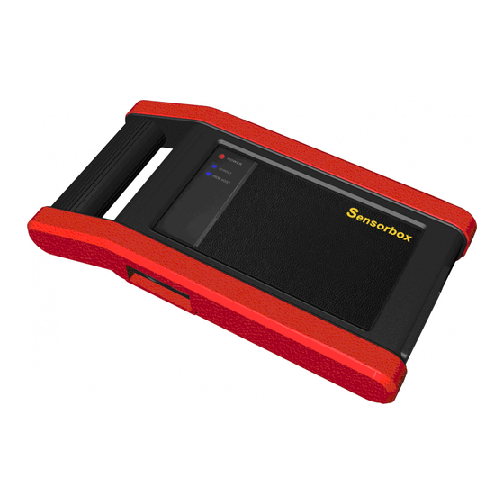
LAUNCH X431 GDS Sensorbox Manual test Input impedance 1000Gohm Input voltage 1~12V 2 Structure and Accessories 2.1 Sensorbox structure Fig. 2-1 Structural diagram of Sensorbox Table 2-1 shows the ports and indicators for X-431 GDS sensorbox No Name Description VΩHz... -
Page 9: Sensorbox Accessories
LAUNCH X431 GDS Sensorbox Manual Power indicator Sensor power indicator, which will be steady red after the sensor module is powered up. Indicator Indicator (Green) for sending data to main sending data to unit. main unit Indicator (Green) for receiving data from main... - Page 10 LAUNCH X431 GDS Sensorbox Manual Fig.2-4 Multimeter probe Fig. 2-5 Electric control convertor cable1 Fig. 2-6 Electric control convertor cable 2 Fig. 2-7 Electric control convertor cable 3 Fig. 2-7 Electric control convertor cable 4...
-
Page 11: Sensor Simulation
LAUNCH X431 GDS Sensorbox Manual 3 Sensor Simulation 3.1 Connection 1. Firstly power on the main unit (connect the main unit module and the DC 12V power supply via the power adapter, or powered via cigarette Lighter cable and the two clamps battery cable);... -
Page 12: Dc Voltage Simulation
LAUNCH X431 GDS Sensorbox Manual simulating water temperature sensor, instead of water temperature sensor, input signal to the microcomputer by simulation function. If the engine work better and the fault symptom disappears, so the fault is in the water temperature sensor. If the fault symptom still occurs, import the signal by ECU port. - Page 13 LAUNCH X431 GDS Sensorbox Manual interface is as shown below Figure 3-2: Fig.3-2 As on "Figure 3-2", click the "Voltage" button on right side, then pop up the menu of "Voltage +" and "voltage -" which can adjust the output voltage value.
-
Page 14: Constant Frequency Simulation
LAUNCH X431 GDS Sensorbox Manual value. [Start]: Continue the following operation [Return]: returns to the previous interface. 3.2.2 Constant frequency simulation Frequency simulation can simulate the square wave signal with pulse frequency of 0.1 ~ 15 kHz, amplitude range of-5V ~ +5 V and duty cycle 10% ~ 90%. -
Page 15: Predefinition Waveform Simulation
LAUNCH X431 GDS Sensorbox Manual Display current square wave signal voltage value [Voltage] Display current square wave signal duty cycle [Duty cycle(%)] After finished setting, click [Start] to perform Constant frequency simulation. 3.2.3 Predefinition waveform simulation X-431 GDS provides the common sensor waveforms which have been defined to facilitate so that users to simulate sensor signals as long as calling out the predefined waveform (after "sensor type"... - Page 16 LAUNCH X431 GDS Sensorbox Manual Fig.3-4 On Figure 3-4, click [Select waveform] button, the interface is shown below as Figure 3-5 Fig.3-5 As on Figure 3-5, the left setting bar shows the sensor type ECT: Coolant Temperature Sensor EVP: EGR Valve Position Sensor HO2S:Heated Oxygen Sensor...
- Page 17 LAUNCH X431 GDS Sensorbox Manual TP: Throttle Position Sensor VAF:Volume Air Flow Sensor VSS: Vehicle Speed Sensor For example, on Figure 3-5, click "ECT" – "Warm up (NTC Thermistor)", the right screen will display the waveforms for the sensor, as shown below Figure 3-6: Fig.3-6...
-
Page 18: Hand-Drawn Waveform
LAUNCH X431 GDS Sensorbox Manual Fig.3-7 As on Figure 3-7, click [Start] button to perform simulation testing. Buttons description: [System]: shows desktop, views current version No, and exits the program. [Help]: provides the operational guide for current interface. [Select waveform]: selects the waveform for the sensor at different operational status. - Page 19 LAUNCH X431 GDS Sensorbox Manual which needs to be simulated in left drawing zone, and setting some parameters such as waveform high level, waveform lower level, and period of waveform, then click [Start], X431 GDS can output a waveform which...
-
Page 20: Precautions On Checking Vehicle Sensor
LAUNCH X431 GDS Sensorbox Manual Fig.3-8 Button description: [System]: shows desktop, views current version No, and exits the program. [Help]: provides the operational guide for current interface. [Draw]: includes functions of "Pencil", "Eraser", and "Empty" [Reference]: outputs the predefined waveform. Users can refer to the predefined waveforms. - Page 21 LAUNCH X431 GDS Sensorbox Manual At first check the fuse, fusible line and connection port. Then check others after eliminating these faults. When measuring voltage, the ignition switch should be turn on and the battery voltage should not be less than 11V.
-
Page 22: Auto Multimeter
LAUNCH X431 GDS Sensorbox Manual terminal/ one cable. When checking the continuity of the terminals, contacts and leads, the method for measuring their resistances can be used Check the faults in the terminals of the CEU to sensors, relays, etc. - Page 23 LAUNCH X431 GDS Sensorbox Manual Fig.4-1 Click the desired testing type as shown on Figure 3-9 to perform related testing. For example select "Voltage test", and then click [Enter] to perform the testing as shown on Figure 4-2...
-
Page 24: Test Sample
LAUNCH X431 GDS Sensorbox Manual Fig.4-2 Buttons description: [System]: displays the desktop functions, view current version No and exit the program. [Help]: views help information for current operations. [Adjust]: functions including: "Zoom in", "Zoom out", "Up", "Down", "Cursor", and "clear". - Page 25 LAUNCH X431 GDS Sensorbox Manual (1)Resistance test for knock sensor Switch ignition "OFF", unplug the wire connector of knock sensor, test the resistance between the wire terminal and the case of knock sensor by the "Resistance test" function, it shall be ∞(disconnected), and if it is 0Ω...
- Page 26 LAUNCH X431 GDS Sensorbox Manual and the temperature is in inversely proportion (negative temperature coefficient), which shall be less than 1kΩ during warming up. Independent testing: Unplug the wire connector of coolant temperature sensor, then remove the sensor from the engine; place the sensor into a breaker with water and heat the water, then use the "Resistance measurement"...
- Page 27 LAUNCH shall not be liable for any consequential or incidental damages. Final determination of defects shall be made by LAUNCH in accordance with procedures established by LAUNCH. No agent, employee, or representative...
- Page 28 LAUNCH X431 GDS Sensorbox Manual Order Information Replaceable and optional parts can be ordered directly from your LAUNCH authorized tool supplier. Your order should include the following information: Quantity Part number Item description Customer Service Department If you have any questions on the operation of the unit, please call:...
- Page 29 LAUNCH X431 GDS Sensorbox Manual Statement: LAUNCH reserves the rights to make any change to product designs and specifications without notice. The actual object may differ a little from the descriptions in the manual in physical appearance, color and configuration. We have tried our best to make the descriptions and...
Need help?
Do you have a question about the Sensorbox X-431 GDS and is the answer not in the manual?
Questions and answers