Table of Contents
Advertisement
Quick Links
Advertisement
Table of Contents

Related Manuals for Asus Q370M-IM-A


Summary of Contents for Asus Q370M-IM-A
- Page 1 Q370M-IM-A...
- Page 2 Product warranty or service will not be extended if: (1) the product is repaired, modified or altered, unless such repair, modification of alteration is authorized in writing by ASUS; or (2) the serial number of the product is defaced or missing.
-
Page 3: Table Of Contents
Contents Chapter 1 Product overview Package contents ................. 1-1 Features ..................1-1 1.3 Specifications ................1-2 Chapter 2 Motherboard information Before you proceed ..............2-1 Motherboard layout ..............2-2 Central Processing Unit (CPU) ........... 2-4 2.3.1 Installing the CPU ............2-5 2.3.2 CPU heatsink and fan assembly installation .... - Page 4 3.4.16 NVMe Configuration ............3-29 3.4.17 HDD Secure Erase ............3-29 3.4.18 HDD/SSD SMART Information ........3-29 Monitor menu ................3-30 Boot menu .................. 3-34 Tool menu ................... 3-38 Exit menu ..................3-39 Appendix Notices .......................A-1 ASUS contact information ...............A-5...
-
Page 5: Chapter 1 Product Overview
Product overview Package contents Check your industrial motherboard package for the following items. 1 x ASUS Q370M-IM-A Motherboard 2 x Serial ATA 6.0 Gb/s cables 1 x ASUS I/O Shield NOTE: If any of the above items is damaged or missing, contact your distributor or sales representative immediately. -
Page 6: Specifications
2 x COM headers(2 x RS232) Front panel I/O 2 x USB 3.2 Gen 1 connectors support additional 4 USB 3.2 Gen ports 1 ports 1 x USB 2.0 connector supports additional 2 USB 2.0 ports (continued on the next page) Q370M-IM-A... - Page 7 1 x CPU Fan connector 2 x Chassis Fan connectors 1 x Chassis intrusion header 1 x Front panel audio connector(AAFP) 1 x System panel connector 1 x Clear CMOS header 1 x Speaker connector Front panel I/O 1 x LPC Debug header ports 1 x LPT port header 1 x 24-pin ATX power connector...
- Page 8 Q370M-IM-A...
-
Page 9: Chapter 2 Motherboard Information
Chapter 2 Motherboard information Before you proceed Take note of the following precautions before you install motherboard components or change any motherboard settings. CAUTION! • Unplug the power cord from the wall socket before touching any component. • Before handling components, use a grounded wrist strap or touch a safely grounded object or a metal object, such as the power supply case, to avoid damaging them due to static electricity. • Hold components by the edges to avoid touching the ICs on them. • Whenever you uninstall any component, place it on a grounded antistatic pad or in the bag that came with the component. -
Page 10: Motherboard Layout
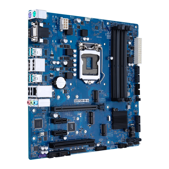
PCIE SATA IRST CHA_FAN1 PCIEX16 PCIEX1_1 Super Intel ® Q370 1083 PCIEX1_2 128Mb MONO_OUT BIOS 2280 2260 2242 M.2_2(SOCKET3) PCIE SATA IRST 64Mb BIOS SATA6G_6 SATA6G_5 LPC_DEBUG COM1 COM2 U32G1_78 USB1112 CLRTC SPEAKER AAFP F_PANEL DIS_ME CHASSIS 12 11 10 9 Q370M-IM-A... - Page 11 Page Connectors/Jumpers/Slots CPU and chassis fan connectors (4-pin CPU_FAN, 4-pin CHA_FAN1/2) 2-16 ATX power connectors (24-pin EATXPWR, 8-pin EATX12V) 2-20 M.2 socket 3 2-18 Intel LGA1151 CPU socket ® DDR4 DIMM slots SATA 6.0Gb/s connectors (7-pin SATA6G_1-6) 2-19 USB 3.2 Gen 1 connectors (U32G1_56; U32G1_78) 2-14 System panel connector (10-1 pin F_PANEL) 2-17 Speaker connector (4-1 pin SPEAKER) 2-16 10. Chassis Intrusion header (4-1 pin CHASSIS) 2-10 11. DIS_ME jumper (3-pin DIS_ME) 2-11 12. Clear RTC RAM (2-pin CLRTC) 2-10 13. USB 2.0 connector (10-1pin USB_1112) 2-15 14. M.2 Wi-Fi 2-18 15. LPC Debug header 2-19 16.
-
Page 12: Central Processing Unit (Cpu)
Central Processing Unit (CPU) The motherboard comes with a surface mount LGA1151 socket designed for the Intel 9th/8th Generation Core™ i9 / i7 / i5 / i3, Pentium , and Celeron processors. ® ® ® LGA1151 IMPORTANT: Unplug all power cables before installing the CPU. CAUTION! • Upon purchase of the motherboard, ensure that the PnP cap is on the socket and the socket contacts are not bent. Contact your retailer immediately if the PnP cap is missing, or if you see any damage to the PnP cap/socket contacts/motherboard components. The manufacturer will shoulder the cost of repair only if the damage is shipment/transit-related. • Keep the cap after installing the motherboard. The manufacturer will process Return Merchandise Authorization (RMA) requests only if the motherboard comes with the cap on the LGA1151 socket. • The product warranty does not cover damage to the socket contacts resulting from incorrect CPU installation/removal, or misplacement/loss/ incorrect removal of the PnP cap. Q370M-IM-A... -
Page 13: Installing The Cpu
2.3.1 Installing the CPU CAUTION! LGA1156 CPU is not compatible with the LGA1151 socket. DO NOT install an LGA1156 CPU on the LGA1151 socket. Chapter 2: Motherboard information... - Page 14 Q370M-IM-A...
-
Page 15: Cpu Heatsink And Fan Assembly Installation
2.3.2 CPU heatsink and fan assembly installation CAUTION! Apply the Thermal Interface Material to the CPU heatsink and CPU before you install the heatsink and fan if necessary. To install the CPU heatsink and fan assembly Chapter 2: Motherboard information... - Page 16 To uninstall the CPU heatsink and fan assembly Q370M-IM-A...
-
Page 17: System Memory
System memory This motherboard comes with four Double Data Rate 4 (DDR4) Dual Inline Memory Module (DIMM) sockets. The figure below illustrates the location of the DDR4 DIMM sockets: Channel Sockets Channel A DIMM_A1 & DIMM_A2* Channel B DIMM_B1 & DIMM_B2* Recommended memory configuration DIMM_B1 DIMM_B2* DIMM_B2* DIMM_A1 DIMM_A2* DIMM_A2* DIMM_A2* Installing a DIMM To remove a DIMM Chapter 2: Motherboard information... -
Page 18: Jumpers
The chassis intrusion sensor or switch sends a low-level signal to this connector when a chassis component is installed. The signal is then generated as a chassis intrusion event. CHASSIS PIN 1 Connector type HEADER 4p, K2, 2.54mm pitch Q370M-IM-A 2-10... - Page 19 Intel ME jumper (3-pin DIS_ME) ® This jumper allows you to enable or disable the Intel ME function. Set this ® jumper to pins 1-2 to enable (default) the Intel ME function and to pins 2-3 to ® disable it. DIS_ME Normal Disable intel (Default) ME function Connector type HEADER 1x3p, 2.54mm pitch, S/T Chapter 2: Motherboard information 2-11...
-
Page 20: Connectors
LAN (RJ-45) ports. These ports allow Gigabit connection to a Local Area Network (LAN) through a network hub. LAN port LED indications Speed Activity Link Activity/Link LED Speed LED Status Description Status Description No link 10Mbps connection Orange Linked ORANGE 100Mbps connection Orange (Blinking) Data activity GREEN 1Gbps connection LAN port Orange (Blinking Ready to wake up then steady) from S5 mode Q370M-IM-A 2-12... - Page 21 Line In port (light blue). This port connects to the tape, CD, DVD player, or other audio sources. Line Out port (lime). This port connects to a headphone or a speaker. In the 4.1, and 5.1 channel configurations, the function of this port becomes Front Speaker Out. Microphone port (pink). This port connects to a microphone. Refer to the audio configuration table for the function of the audio ports in 2.1, 4.1, 5.1, or 7.1-channel configuration. USB 2.0 ports. These 4-pin Universal Serial Bus (USB) ports are for USB 2.0/1.1 devices. DisplayPorts. These ports are for DisplayPort-compatible devices. 10. HDMI port. This port is for a High-Definition Multimedia Interface (HDMI) connector, and is HDCP compliant allowing playback of HD DVD, Blu-ray, and other protected content. 11. PS/2 keyboard port (purple). This port is for a PS/2 keyboard. Chapter 2: Motherboard information 2-13...
-
Page 22: Internal Connectors
U32G1_56 PIN 1 USB3+5V USB3+5V IntA_P1_SSRX- IntA_P2_SSRX- IntA_P1_SSRX+ IntA_P2_SSRX+ IntA_P1_SSTX- IntA_P2_SSTX- IntA_P1_SSTX+ IntA_P2_SSTX+ IntA_P1_D- IntA_P2_D- IntA_P1_D+ IntA_P2_D+ PIN 1 U32G1_78 Connector type BOX HD 2x10p, K20, 2.0mm pitch LPT connector (26-1pin LPT) The LPT (Line Printing Terminal) connector supports devices such as a printer. LPT standardizes as IEEE 1284, which is the parallel port interface on IBM PC-compatible computers. PIN 1 Q370M-IM-A 2-14... - Page 23 USB 2.0 connector (10-1 pin USB1112) This connector is for an USB 2.0 port. Connect the USB cable to this connector. This USB connector complies with USB 2.0 specification that supports up to 480 Mbps connection speed. USB1112 PIN 1 Connector type Header 2x5p, K9, 2.54mm pitch CAUTION! Never connect a 1394 cable to the USB connector. Doing so will damage the motherboard. NOTE: The USB cable is purchased separately. MONO out header (2-pin MONO_OUT) This internal mono out header allows connection to an internal, low power speaker for basic system sound capability. You can connect a 3W speaker to this header, but the subsystem is capable of driving a speaker load of 2 Ohms at 2 Watts (rms). MONO_OUT R_OUT+ R_OUT- PIN 1 Chapter 2: Motherboard information 2-15...
- Page 24 CAUTION: Do not forget to connect the fan cables to the fan connectors. Insufficient air flow inside the system may damage the motherboard components. These are not jumpers! Do not place jumper caps on the fan connectors! Speaker connector (4-pin SPEAKER) The 4-pin connector is for the chassis-mounted system warning speaker. The speaker allows you to hear system beeps and warnings. SPEAKER PIN 1 Connector type HEADER 1x4p, 2.54mm pitch, S/T Q370M-IM-A 2-16...
- Page 25 Front panel system panel connector (10-1 pin F_PANEL) This connector supports several chassis-mounted functions. F_PANEL Connector type Header 2x5p, K10, 2.54mm pitch • System power LED (2-pin +PWR_LED) This 2-pin connector is for the system power LED. Connect the chassis power LED cable to this connector. The system power LED lights up when you turn on the system power, and blinks when the system is in sleep mode. • Hard disk drive activity LED (2-pin +HDD_LED) This 2-pin connector is for the HDD Activity LED. Connect the HDD Activity LED cable to this connector. The IDE LED lights up or flashes when data is read from or written to the HDD. • ATX power button/soft-off button (2-pin PWR_BTN) This 2-pin connector is for the system power button.
- Page 26 M.2 socket 3 These sockets allow you to install M.2 SSD modules. M.2_1(SOCKET3) M.2_2(SOCKET3) NOTES: • The M.2 SSD module is purchased separately. • These sockets support M Key and 2242/2260/2280 storage devices. M.2 Wi-Fi This socket connects to an M.2 Wi-Fi device. M.2(WIFI) NOTE: The M.2 Wi-Fi module is purchased separately. Q370M-IM-A 2-18...
- Page 27 SATA6G_3 RSATA_RXN SATA6G_4 RSATA_RXP SATA6G_5 SATA6G_6 Connector type WAFER HD 7p, 1.27mm pitch 11. LPC Debug header This header allows connection to a LPC Debug card. LPC Debug header Connector type HEADER 2x5p, K10, 2.0mm pitch IMPORTANT! • Scan the QR code to view the meaning of each debugging code. • Debugging codes are only available for ASUS LPC Debug cards. • Contact your region sales representative for LPC Debug cards ordering. Chapter 2: Motherboard information 2-19...
- Page 28 +12V DC +12 Volts +5 Volts +12V DC +5 Volts +12 Volts +12V DC +5V Standby +5 Volts +12V DC Power OK -5 Volts +5 Volts +5 Volts PSON# +3 Volts -12 Volts +3 Volts +3 Volts PIN 1 Q370M-IM-A 2-20...
- Page 29 14. Front panel audio connector (10-1 pin AAFP) This connector is for a chassis-mounted front panel audio I/O module that supports HD Audio standard. Connect one end of the front panel audio I/O module cable to this connector. AAFP PIN 1 HD-audio-compliant pin definition Connector type HEADER 2x5p, K8, 2.54mm pitch IMPORTANT! • We recommend that you connect a high-definition front panel audio module to this connector to avail of the motherboard’s high-definition audio capability. • If you want to connect a high-definition front panel audio module to this connector, set the HD Audio Controller item in the BIOS setup to [Enabled]. Chapter 2: Motherboard information 2-21...
- Page 30 Q370M-IM-A 2-22...
-
Page 31: Chapter 3 Bios Setup
Always shut down the system properly from the operating system. IMPORTANT: • Visit the ASUS website at www.asus.com to download the latest BIOS file for this motherboard. • The default BIOS settings for this motherboard apply to most working conditions and ensures optimal performance. -
Page 32: Bios Menu Screen
Clock (RTC) RAM to clear the BIOS password. See section 2.5 Jumpers for information on how to erase the RTC RAM. The Administrator or User Password items on top of the screen show • the default Not Installed. After you set a password, these items show Installed. Q370M-IM-A... - Page 33 Administrator Password If you have set an administrator password, we recommend that you enter the administrator password for accessing the system. To set an administrator password: Select the Administrator Password item and press <Enter>. From the Create New Password box, key in a password, then press <Enter>.
-
Page 34: Ai Tweaker Menu
If you assign a value for 2-Core Ratio Limit, do not set the 1-Core Ratio Limit to [Auto]. 3-Core Ratio Limit Enter [Auto] to apply the CPU default Turbo Ratio setting or manually assign a 3-core ratio limit that must be higher than or equal to the 4-core ratio limit. Q370M-IM-A... -
Page 35: Dram Odd Ratio Mode
If you assign a value for 3-Core Ratio Limit, do not set the 1-Core Ratio Limit and 2-Core Ratio Limit to [Auto]. 4-Core Ratio Limit Enter [Auto] to apply the CPU default Turbo Ratio setting or manually assign a 4-core ratio limit that must be higher than or equal to the 5-core ratio limit. -
Page 36: Power-Saving & Performance Mode
Configuration option: [Auto] DRAM RAS# to RAS# Delay S Configuration option: [Auto] DRAM REF Cycle Time Configuration option: [Auto] DRAM Refresh Interval Configuration option: [Auto] DRAM WRITE Recovery Time Configuration option: [Auto] DRAM READ to PRE Time Configuration option: [Auto] Q370M-IM-A... - Page 37 DRAM FOUR ACT WIN Time Configuration option: [Auto] DRAM WRITE to READ Delay Configuration option: [Auto] DRAM WRITE to READ Delay L Configuration option: [Auto] DRAM WRITE to READ Delay S Configuration option: [Auto] DRAM CKE Minimum Pulse Width Configuration option: [Auto] DRAM Write Latency Configuration option: [Auto] Skew Control...
- Page 38 Clk Falling Slope Offset Configuration option: [Auto] RTL IOL Control DRAM RTL INIT Value Configuration option: [Auto] DRAM RTL (CHA DIMM0 Rank0) Configuration option: [Auto] DRAM RTL (CHA DIMM0 Rank1) Configuration option: [Auto] DRAM RTL (CHA DIMM1 Rank0) Configuration option: [Auto] Q370M-IM-A...
- Page 39 DRAM RTL (CHA DIMM1 Rank1) Configuration option: [Auto] DRAM RTL (CHB DIMM0 Rank0) Configuration option: [Auto] DRAM RTL (CHB DIMM0 Rank1) Configuration option: [Auto] DRAM RTL (CHB DIMM1 Rank0) Configuration option: [Auto] DRAM RTL (CHB DIMM1 Rank1) Configuration option: [Auto] DRAM IOL (CHA DIMM0 Rank0) Configuration option: [Auto] DRAM IOL (CHA DIMM0 Rank1)
- Page 40 Write Timing Centering 2D Configuration options: [Enabled] [Disabled] Read Timing Centering 2D Configuration options: [Enabled] [Disabled] Command Voltage Centering Configuration options: [Enabled] [Disabled] Write Voltage Centering 2D Configuration options: [Enabled] [Disabled] Read Voltage Centering 2D Configuration options: [Enabled] [Disabled] Q370M-IM-A 3-10...
- Page 41 Late Command Training Configuration options: [Auto] [Enabled] [Disabled] Round Trip Latency Configuration options: [Auto] [Enabled] [Disabled] Turn Around Timing Training Configuration options: [Enabled] [Disabled] Rank Margin Tool Configuration options: [Enabled] [Disabled] Memory Test Configuration options: [Enabled] [Disabled] DIMM SPD Alias Test Configuration options: [Enabled] [Disabled] Receive Enable Centering 1D Configuration options: [Enabled] [Disabled]...
- Page 42 Configuration options: [Enable Both DIMMs] [Disable DIMM0] [Disable DIMM1] [Disable Both DIMMs] Channel B DIMM Control Allows you to enable or disable the Channel B DIMM slots. Configuration options: [Enable Both DIMMs] [Disable DIMM0] [Disable DIMM1] [Disable Both DIMMs] Q370M-IM-A 3-12...
- Page 43 Enable this item to enhance the stability of your system. Disable this item to enhance the DRAM overclocking capability. Configuration options: [Auto] [Enabled] [Disabled] Training Profile Configuration options: [Auto] [Standard Profile] [ASUS User Profile] DLLBwEn Configuration option: [Auto] SPD Write Disable...
-
Page 44: Digi+ Vrm
VRM thermal. Select from level 1 to 7 to adjust the GT power voltage from 0% to 100%. Configuration options: [Auto] [Level 1] [Level 2] [Level 3] [Level 4] [Level 5] [Level 6] [Level 7] The boosted performance may vary depending on the GT specification. Do not remove the thermal module. Q370M-IM-A 3-14... -
Page 45: Internal Cpu Power Management
3.3.8 Internal CPU Power Management The subitems in this menu allow you to set the CPU ratio and features. Intel(R) SpeedStep(tm) Allows the operating system to dynamically adjust the processor voltage and cores frequency to decrease the average power consumption and decrease average heat production. -
Page 46: Cpu Graphics Current Limit
Configuration option: [Auto] DRAM DATA REF Voltage on CHA DIMM1 Rank0 BL0-7 Configures the DRAM Data REF Voltage. Configuration option: [Auto] DRAM DATA REF Voltage on CHA DIMM1 Rank1 BL0-7 Configures the DRAM Data REF Voltage. Configuration option: [Auto] Q370M-IM-A 3-16... - Page 47 DRAM DATA REF Voltage on CHB DIMM0 Rank0 BL0-7 Configures the DRAM Data REF Voltage. Configuration option: [Auto] DRAM DATA REF Voltage on CHB DIMM0 Rank1 BL0-7 Configures the DRAM Data REF Voltage. Configuration option: [Auto] DRAM DATA REF Voltage on CHB DIMM1 Rank0 BL0-7 Configures the DRAM Data REF Voltage.
-
Page 48: Advanced Menu
This item allows you to select the PCI Express L1 Substates settings. Configuration options: [Disabled] [L1.1] [L1.1 & L1.2] PCI Express Clock Gating This item allows you to enable or disable PCI Express Clock Gating for each port. Configuration options: [Disabled] [Enabled] Q370M-IM-A 3-18... -
Page 49: Cpu Configuration
CPU and PCH sides must be enabled for the ASPM to take effect. Configuration options: [Disabled] [L0s] [L1] [L0sL1] PEG-ASPM This item allows you to select the ASPM state for energy-saving conditions, or use the ASUS optimized energy saving profile. Configuration options: [Disabled] [Auto] [ASPM L0s] [ASPM L1] [ASPM L0sL1] 3.4.2 CPU Configuration The items in this menu show CPU-related information the BIOS automatically detects. - Page 50 The following items appear only when you set the CPU C-States to [Enabled]. Enhanced C-states [Enabled] [Enabled] Enables enhanced C1 state. [Disabled] Disables enhanced C1 state. CPU C3 Report [Enabled] Allows you to disable or enable the CPU C3 report to OS. Configuration options: Q370M-IM-A 3-20...
-
Page 51: System Agent (Sa) Configuration
[Enabled] [Disabled] CPU C6 Report [Disabled] Allows you to disable or enable the CPU C6 report to OS. Configuration options: [Enabled] [Disabled] CPU C7 Report [Disabled] Allows you to disable or enable the CPU C7 report to OS. Configuration options: [Disabled] [CPU C7] [CPU C7s] CPU C8 Report [Disabled] Allows you to disable or enable the CPU C8 report to OS. -
Page 52: Pch Configuration
Configuration options: [Disabled] [Enabled in S4-S5] 3.4.5 PCH Storage Configuration While entering Setup, the BIOS automatically detects the presence of SATA devices. The SATA Port items show Empty if no SATA device is installed to the corresponding SATA port. Q370M-IM-A 3-22... -
Page 53: Pch-Fw Configuration
SATA Controller(s) Enables or disables onboard the SATA device. Configuration options: [Disabled] [Enabled] The following items appear only when you set SATA Controller(s) to [Enabled]. SATA Mode Selection Determines how SATA controller(s) operate. This PCH SKU does not support RST feature. Configuration options: [AHCI] [Intel RST Premium with Intel Optane System Acceleration (RAID)] Aggressive LPM Support... -
Page 54: Trusted Computing
Allows you to enable or disable SHA256 PCR Bank. Configuration options: [Enabled] [Disabled] Pending operation Allows you to schedule an operation for security devices. Reboot your system for the changes to take effect. Configuration options: [None] [TPM Clear] Q370M-IM-A 3-24... -
Page 55: Onboard Devices Configuration
Platform Hierarchy Allows you to enable or disable Platform Hierarchy. Configuration options: [Enabled] [Disabled] Storage Hierarchy Allows you to enable or disable Storage Hierarchy. Configuration options: [Enabled] [Disabled] Endorsement Hierarchy Allows you to enable or disable Endorsement Hierarchy. Configuration options: [Enabled] [Disabled] TPM2.0 UEFI Spec Version Allows you to select the TCG2 spec version support. - Page 56 Parallel Port Configuration Allows you to set parameters of Parallel Port. Parallel Port Allows you to enable or disable the parallel port (LPT/LPTE). Configuration options: [Disabled] [Enabled] The following item appears only when you set Serial Port to [Enabled]. Q370M-IM-A 3-26...
-
Page 57: Apm Configuration
Change Settings Allows you to choose the setting for Super IO device. Configuration options: [Auto] [IO=378h; IRQ=5] [IO=378h; IRQ=5,6,7,9,10,11,12] [IO=278h; IRQ=5,6,7,9,10,11,12] [IO=3BCh; IRQ=5,6,7,9,10,11,12] Device Mode This item allows you to change the Printer Port mode. Configuration options: [STD Printer Mode] [SPP Mode] [EPP-1.9 and SPP Mode] [EPP-1.7 and SPP Mode] [ECP Mode] [ECP and EPP 1.9 Mode] [ECP and EPP 1.7 Mode] 3.4.10... -
Page 58: Intel Txt Information
USB devices are only available when running BIOS Setup. [Auto] Allows the system to detect the presence of USB devices at startup. If detected, the USB controller legacy mode is enabled. If no USB device is detected, the legacy USB support is disabled. Q370M-IM-A 3-28... -
Page 59: Network Stack Configuration
XHCI Hand-off This item is set to [Disabled] by default for the EHCI (enhanced host controller interface) support by XHCI drivers in operating systems. [Disabled] Support XHCI by XHCI drivers for operating systems with XHCI support. [Enabled] Support XHCI by BIOS for operating systems without XHCI support. -
Page 60: Monitor Menu
CPU Fan Step Down This item allows you to set the value of the CPU fan step down. Configuration options: [0 sec] [2.1 sec] [2.8 sec] [3.6 sec] [4.2 sec] [5.0 sec] [6.3 sec] [8.5 sec] [12 sec] [25 sec] Q370M-IM-A 3-30... - Page 61 CPU Fan Speed Low Limit This item appears only when you enable the CPU Q-Fan Control feature and allows you to disable or set the CPU fan warning speed. Configuration options: [Ignore] [200RPM] [300 RPM] [400 RPM] [500 RPM] [600RPM] CPU Fan Profile This item appears only when you enable the CPU Q-Fan Control feature and allows you to set the appropriate performance level of the CPU fan.
- Page 62 Sets to [Turbo] to achieve maximum chassis fan speed. [Manual] Sets to [Manual] to assign detailed fan speed control parameters. The following four items appear only when you set Chassis Fan1/2 Q-Fan Control to [PWM mode] and Chassis Fan 1/2 Profile to [Manual]. Q370M-IM-A 3-32...
- Page 63 Chassis Fan 1/2 Upper Temperature Use the <+> and <-> keys to adjust the upper limit of the chassis temperature. Chassis Fan 1/2 Max. Duty Cycle(%) Use the <+> and <-> keys to adjust the maximum chassis fan duty cycle. When the chassis temperature reaches the upper limit, the chassis fan will operate at the maximum duty cycle.
-
Page 64: Boot Menu
Normal Boot. The values range from 0 to 10 seconds. This feature will only work under normal boot. Bootup NumLock State This item allows you to enable or disable power-on state of the NumLock. Configuration options: [On] [Off] Q370M-IM-A 3-34... - Page 65 Wait for ‘F1’ If Error When this item is set to [Enabled], the system waits for the F1 key to be pressed when error occurs. Configuration options: [Disabled] [Enabled] Option ROM Messages [Force BIOS] The third-party ROM messages will be forced to display during the boot sequence.
- Page 66 This item allows you to delete the PK from your system. Once the PK is deleted, all the system’s Secure Boot keys will not be active. KEK Management The KEK (Key-exchange Key or Key Enrollment Key) manages the Signature database (db) and Revoked Signature database (dbx). Q370M-IM-A 3-36...
- Page 67 Key-exchange Key (KEK) refers to Microsoft® Secure Boot Key-Enrollment Key (KEK). Save to File Allows you to save the downloaded KEK to a USB storage device. Set New Key Allows you to load the downloaded KEK from a USB storage device. Append Key Allows you to load the additional KEK from a storage device for an additional db and dbx loaded management.
-
Page 68: Tool Menu
<Enter> to display the submenu. ASUS EZ Flash 3 Utility This item allows you to run ASUS EZ Flash 3 utility. When you press <Enter>, a confirmation message appears. Use the left/right arrow key to select between [Yes] or [No], then press <Enter>... -
Page 69: Exit Menu
ASUS User Profile This item allows you to save and load BIOS setting and profiles. Profile Name This item allows you to key in a profile name. Save to Profile This item allows you to save the current BIOS settings to the BIOS Flash, and create a profile. - Page 70 Q370M-IM-A 3-40...
-
Page 71: Appendix
Appendix Notices FCC Compliance Information Responsible Party: Asus Computer International Address: 48720 Kato Rd., Fremont, CA 94538, USA Phone / Fax No: (510)739-3777 / (510)608-4555 This device complies with part 15 of the FCC Rules. Operation is subject to the following two conditions: (1) This device may not cause harmful interference, and (2) this device must accept any interference received, including interference that may cause undesired operation. - Page 72 : (1) l’appareil ne doit pas produire de brouillage, et (2) l’utilisateur de l’appareil doit accepter tout brouillage radioélectrique subi, même si le brouillage est susceptible d’en compromettre le fonctionnement. CAN ICES-3(B)/NMB-3(B) VCCI: Japan Compliance Statement Class B ITE KC: Korea Warning Statement Q370M-IM-A...
- Page 73 ASUS Recycling/Takeback Services ASUS recycling and takeback programs come from our commitment to the highest standards for protecting our environment. We believe in providing solutions for you to be able to responsibly recycle our products, batteries, other components as well as the packaging materials.
- Page 74 доступний на: www.asus.com/support Cijeli tekst EU izjave o sukladnosti dostupan je na: www.asus.com/support Türkçe AsusTek Computer Inc., bu aygıtın temel gereksinimlerle ve ilişkili Čeština Společnost ASUSTeK Computer Inc. tímto prohlašuje, že toto Yönergelerin diğer ilgili koşullarıyla uyumlu olduğunu beyan eder.
-
Page 75: Asus Contact Information
+1-510-739-3777 +1-510-608-4555 Web site https://www.asus.com/us/ Technical Support Support fax +1-812-284-0883 Telephone +1-812-282-2787 Online support https://qr.asus.com/techserv ASUS COMPUTER GmbH (Germany and Austria) Address Harkortstrasse 21-23, 40880 Ratingen, Germany Web site https://www.asus.com/de Online contact https://www.asus.com/support/Product/ContactUs/ Services/questionform/?lang=de-de Technical Support Telephone (DE) +49-2102-5789557 Telephone (AT) - Page 76 Q370M-IM-A...
Need help?
Do you have a question about the Q370M-IM-A and is the answer not in the manual?
Questions and answers