Table of Contents
Advertisement
Quick Links
REMOTE GSM SWITCH GRM-10
DESCRIPTION
The GRM-10 device is designed to
realise simple control and notice opera-
tions. The operations are carried out by
means of the GSM network. The control-
ler has two independent outputs with a
maximum load capacity of 16 A / 250 V
AC. Two digital inputs allow for a link with
the alarm control panels. The RS485 in-
terface in connection with the RXM-01
translator gives a possibility to control
EXTA FREE system receivers with the
help of a mobile phone and messages
that are defined by the user. The number
of operation modes and configuration
options make the GRM-10 a very useful
device for simple home automation and
industrial systems. The GRM-10 device
is made in a three-MOD casing and is
designed for mounting in switchboards
on a TH35 rail.
FEATURES
● Remote control of the electrical de-
vices by means of commands (in-
coming phone connection, text mes-
sage) sent from a mobile phone,
● Comfortable control of difficult ac-
cess devices (air conditioning, heat-
ing, etc.),
● Two relay outputs with the load ca-
pacity of 16 A,
● Operation is optically signalled (pow-
er supply, relay status, GSM modem
status)
● Low power consumption, a possibility
of continuous operation.
The device is designed for single-
phase installation and must be installed
in accordance with standards valid in a
particular country. The device should
be connected according to the details
CAUTION
included in this operating manual.
Installation, connection and control should be car-
ried out by a qualified electrician staff, who act in
accordance with the service manual and the device
functions. In case of casing dismantling an electric
shock may occur, and the guarantee is lost then.
Before installation make sure the connection cables
are not under voltage. The cruciform head screw-
driver 3,5 mm should be used to instal the device.
Improper transport, storage, and use of the device
influence its wrong functioning. It is not advisable
to instal the device in the following cases: if any
device part is missing or the device is damaged or
deformed. In case of improper functioning of the de-
vice contact the producer.
The symbol means selective
collecting of electrical and electronic
equipment. It is forbidden to put the
used equipment together with other
waste.
ZAMEL Sp. z o.o.
ul. Zielona 27, 43-200 Pszczyna, Poland
Tel. +48 (32) 210 46 65, Fax +48 (32) 210 80 04
www.zamelcet.com, e-mail: marketing@zamel.pl
TECHNICAL PARAMETERS
Nominal input rated voltage: 230 V AC 50 / 60 Hz
Input voltage tolerance: -15 ÷ +10 %
Nominal power consumption: 1,5 W
Supply voltage optical signalling: LED diode (green)
GSM status signalling: LED diode (yellow)
Output status signalling: 2 x LED diode
Output relays parameters: 2 x NO 16 A / 250 V AC AC1 4000 VA
RS485 transmission signalling: LED diode
Position on RS485 bus: only MASTER
Ambient temperature range: -10 ÷ +55
Operating position: free
Casing mounting: TH35 rail
Casing protection degree: IP20 (PN-EN 60529)
Overvoltage category: II
Reference standard: PN-EN 60950-1:2007; PN-EN 55024:2000;
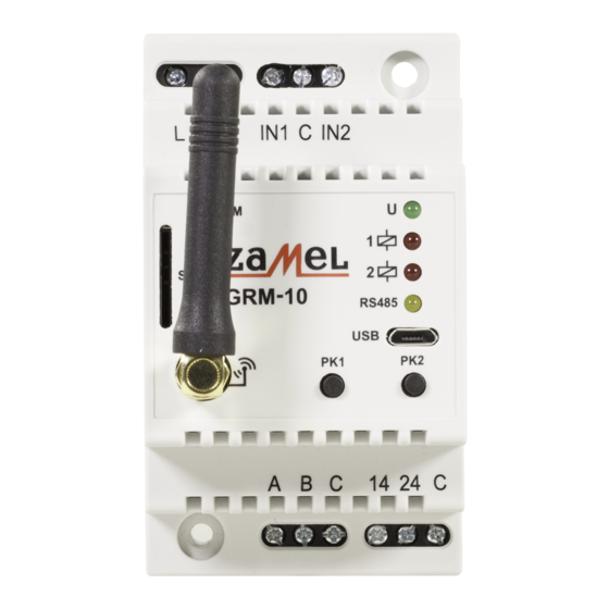
APPEARANCE
GSM range signalling
SIM card input
GSM antenna
GRM-10
GSM frequency: 900/1800/1900 MHz
Operating range: restricted by the GSM network
Output number: 2
Input number: 2
Input type: Digital - potential +4 V
RS485 MODBUS - A,B,C terminals; USB;
Interfaces:
PK1, PK2 push-buttons
C
o
Protection class: II
Pollution degree: 2
Dimensions: 3-modular casing
Weight: 163 g
PN-EN 61000-4-4
MANUAL INSTRUCTION
Power supply terminals
Input terminals
Power supply signalling
Relay 1 (LEDP1)
status signalling
Relay 2 (LEDP2)
status signalling
RS-485 transmission
signalling
MICRO USB input
PK1, PK2 push-buttons
Output terminals
RS485 Interface
plik: inst_ext_pl_grm-10_gb | modyfikacja: 03.06.2013
Advertisement
Table of Contents

Subscribe to Our Youtube Channel
Related Manuals for Zamel GRM-10


Summary of Contents for Zamel GRM-10
- Page 1 The number Input number: 2 of operation modes and configuration Input type: Digital - potential +4 V options make the GRM-10 a very useful RS485 MODBUS - A,B,C terminals; USB; device for simple home automation and Interfaces: PK1, PK2 push-buttons industrial systems.
- Page 2 SOFTWARE UPGRADE The GRM-10 user has the ability to upgrade the software using the Micro USB interface. It may be necessary in case of an upgrade release by the producer. Information on the current software can be found on the product website: http://www.zamelcet.com/pl,263,4537,sterownik_gsm_modulowy_2kanalowy_grm10.html.
- Page 3 CONFIGURATION MODE END COMMAND The command allows the the GRM-10 device to go out from the configuration mode to normal operation. The active command is only for the numbers included in the ADMIN list (by means of ADMIN command or the PC application). The command is inactive during...
- Page 4 Default MODBUS protocol configuration in GRM-10 device allows for a direct connection with EXTA FREE translator / RS-485 RXM-01 type. GRM-10 device in such a connection is only a MASTER on the MODBUS bus - it receives control text messages and by means of RS-485 bus it sends appropriate commands to the RXM-01 device.
- Page 5 TIME – defines that after an occurrence of the <LO/HI> status in IN1 / IN2 input, the OUT1/OUT2 output changes its status for a time limited by <t1> <t2> parameters. NONE – defines that after an occurrence of the <LO/HI> status in IN1 / IN2 input, the GRM-10 device avoids the status (it does not re- spond).
- Page 6 GRM-10 device and other devices in cooperation. ● It is important to switch off the PIN code or adjust the code to 1111 before installing the SIM card in the GRM-10 device. ● It is recommended to switch of the VOICEMAIL service on the card installed in the GRM-10 DEVICE.
- Page 7 X-ON Electronics Authorized Distributor Click to view similar products for category: LED Lighting Fixture Accessories RZB03 ASM10 ORDBYE115 STR21230V AS223 ORAE1336G ORAE1373 ORWE501 ORWE504 ORWE514...
Need help?
Do you have a question about the GRM-10 and is the answer not in the manual?
Questions and answers