Table of Contents
Advertisement
Quick Links
Advertisement
Table of Contents

Related Manuals for Octave HP 700


Summary of Contents for Octave HP 700
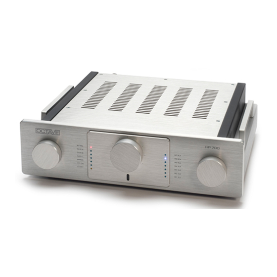
- Page 1 HP 700...
- Page 2 We have specialized in tube amplification for the past 30 years, during which time we have developed a number of innovative technologies that have earned us a reputation as one of the leaders in the field. We hope you will enjoy many hours of wonderful music with your OCTAVE preamplifier. Andreas Hofmann...
-
Page 3: Table Of Contents
CONTENTS OCTAVE TECHNOLOGY ......................5 OCTAVE amps in contrast to other tube amplifiers ..............5 Description HP 700 ........................6 SAFETY INSTRUCTIONS......................7 Before you begin ........................7 2.1.1. In case of emergency: disconnect the plug from the mains supply ....... 7 2.1.2. - Page 4 Assembling the phono input modules ..............26 11.2.4. Available phono input modules: see inlay manual “In- and Output Modules”..26 Option: HP 700 with control unit ..................... 27 Option: HP 700 with stepped attenuator ................. 29 TROUBLESHOOTING ......................30 Troubleshooting ........................30 TECHNICAL DATA ........................
-
Page 5: Octave Technology
OCTAVE amps in contrast to other tube amplifiers Sound The design goal of OCTAVE amplifiers is honest, natural sound reproduction. The sound characteristics of an amplifier are derived from the sum of all its parts. Tubes themselves do not guarantee high quality sound. -
Page 6: Description Hp 700
OCTAVE TECHNOLOGY Description HP 700 Description HP 700 HP 700 is a member of a new generation of tube amplifiers built by OCTAVE. The first model of this line was the Jubilee reference preamplifier, followed by the HP 500 SE... -
Page 7: Safety Instructions
Defective fuses should also only be replaced by a qualified technician. Always replace fuses with ones of the same type and rating. If your amplifier requires servicing, please ship or take your equipment directly to OCTAVE or to one of our authorized service centers. -
Page 8: Before Connecting
Placement 2.2.1. Location OCTAVE equipment is designed strictly for use in a dry domestic environment. Do not use it in open air or in damp environments! Never place plants or liquid-filled containers on your amplifier. Take care that objects do not fall ... -
Page 9: Setting Up
Switch on the other components in any order. Running in All OCTAVE equipment is subject to a 48-hour endurance run to burn in the tubes. The tubes are preselected for use in each particular model. The sound quality of tube equipment improves... -
Page 10: Operation
OPERATION HP 700 front panel OPERATION HP 700 front panel Legend Mode switch The muting, line stage gain, home theater bypass multi-channel func- (function switch) tion, and tone control are activated here. Muting The muting LED illuminates when muting is on and during the start-up phase. -
Page 11: Connections
CONNECTIONS HP 700 rear panel CONNECTIONS HP 700 rear panel Legend GND connection Ground connection for phono IN 1 SL1 Slot for a phono or line input module IN 2 SL2 Slot for a phono or line input module IN 5 RCA input Line-level input for CD, tuner, etc. - Page 12 CONNECTIONS HP 700 rear panel Legend (12) IN 4 XLR input Balanced line-level input for CD, DAC, in bypass setting, can be used as alternative home theater input. (13) RCA bypass Home theater input for multi-channel receiver (14) Monitor outputs Unregulated outputs for recording equipment, computers, etc.
-
Page 13: External Power Supply
EXTERNAL POWER SUPPLY Front of power supply EXTERNAL POWER SUPPLY HP 700 is switched on and off using a switch on the power supply. Front of power supply Legend (20) Power (switch) The LED on the power supply illuminates when the power supply is on. -
Page 14: Multi-Channel Mode
(e.g. doubled power amplifiers, doubled speakers, etc.) or have to fiddle with plugs every time they want to hear multi-channel and classic stereo. The HP 700 is the solution to this problem. With the 700, it is possible to use the two-channel amplifier/speaker combination as part of the multi-channel system. - Page 15 MULTI-CHANNEL MODE The HP 700 in multi-channel mode Multi-channel source DVD player, etc. RCA/XLR RCA/XLR input R input L Three-channel power Stereo/mono power amplifier for the amplifier additional channels Front – main loudspeaker In multi-channel mode, i.e. in the “bypass” setting, the common volume of the multi-channel system has to be set on the multi-channel source.
-
Page 16: Remote Control For Volume
REMOTE CONTROL FOR VOLUME Remote control operating elements REMOTE CONTROL FOR VOLUME Remote control operating elements Legend Volume up Volume down Battery replacement Use a “Philips 1” screwdriver to disassemble the base plate. Remove the batteries. Insert two new AAA 1.5 V batteries. Make sure not to press the buttons while inserting the batteries! If the remote control does not work after the batteries are replaced, remove the new batteries and wait at least 2 hours. -
Page 17: Tubes
TUBES Line tube layout with adjustment capability TUBES Line tube layout with adjustment capability WARNING Electric shock! Parts carrying dangerous voltages may be exposed when opening the cover and injury through electric shock. ► Before opening the cover, switch the device off and unplug the power cord. Tube layout: line board Tube layout: line board ECC82 (12 AU 7 ) -
Page 18: Phono Tube Layout
TUBES Phono tube layout Phono tube layout German designation International designation ECC 83 12 AX 7 ECC 81 12 AT 7 ECC 88 6922, 6 DJ 8... -
Page 19: Control Unit Tube Layout
TUBES Control unit tube layout Control unit tube layout German designation International designation ECC 88 6922, 6 DJ 8 Replacing the V 7 tube Note The control unit cannot be disassembled during tube replacement, as it is physically connected to the front. Disassemble the shortened cover. -
Page 20: Replacing Tubes
TUBES Replacing tubes Replacing tubes ATTENTION Improper disassembly Damage to the tubes due to improper disassembly or assembly. ► Changing tubes is a job for qualified technicians! Switch off the preamplifier, unplug the power cord from the wall socket, and allow the unit 10 minutes to cool down. -
Page 21: Output Resistance
OUTPUT RESISTANCE Adjusting the output resistance OUTPUT RESISTANCE Adjusting the output resistance Resistance selector switch To change the output resistance of the line stage, set the resistance switch to LOW (100 ohm) or HIGH (300 ohm). This allows you to adapt the preamplifier to the properties of the signal cable and the input resistance of the power amplifier. -
Page 22: Options
Option: Additional line-level input module The modular design of the HP 700 offers the option to mount one or two additional line-level inputs beyond the existing line-level inputs (if the phono option is not installed, which requires at least one slot). -
Page 23: Available Line-Level Input Modules: S Ee Inlay Manual "In- And Output Modules
Option: Additional line-level input module Secure the module to the front side of the HP 700 first using screws from the front panel. Carefully screw in all the screws to the terminal screw strip. Do not tighten them too much. -
Page 24: Option Hp 700 With Phono
Option HP 700 with phono Option HP 700 with phono 11.2.1. HP 700 with phono RIAA A record player is an electro-mechanical device. Music signals are “pressed” into the grooves in the record, and these are physically tracked and read by the pickup cartridge. In order to get the entire... -
Page 25: Subsonic Filter
OPTIONS Option HP 700 with phono 11.2.2. Subsonic filter Warped records and unfavorable pickup cartridge/pickup arm combinations can cause major low- frequency interference that impairs bass reproduction. These low-frequency levels can be attenuated with the switchable subsonic filter. The corner frequency is outside of the audible range at 15 Hz. -
Page 26: Assembling The Phono Input Modules
OPTIONS Option HP 700 with phono 11.2.3. Assembling the phono input modules The phono input modules are assembled in the same way as the line input modules, though their assembly is simpler due to an absence of cables to be connected. -
Page 27: Option: Hp 700 With Control Unit
OPTIONS Option: HP 700 with control unit Option: HP 700 with control unit Legend (25) Output selector switch Here, the three outputs RCA 1, RCA 2, and XLR can be acti- vated separately and in groups. In the ALL ON setting, all three inputs are active and can be used simultaneously. - Page 28 OPTIONS Option: HP 700 with control unit The components used, low-noise conductive plastic controls with minimal channel tolerance, and low-tolerance polypropylene capacitors, in conjunction with the latest optimized tube stage advance the sound properties of the classic tone control to an unprecedented level. Precise adjustment allows for tonal corrections in the bass or treble ranges.
-
Page 29: Option: Hp 700 With Stepped Attenuator
– as in the balance controls – is frequency-compensated. Equipped with this unique switching layout, the OCTAVE stepped attenuator functions as an ideal control. The sound characteristics are constant across the entire control range, while the center position also remains stable across the entire range thanks to the negligible channel tolerance. -
Page 30: Troubleshooting
You can isolate the aerial earth connection with a special signal isolator. This device has no adverse effect on the sound or picture quality of tuners or TVs. The HP 700 is not grounded and therefore cannot cause ground loops. Solution... -
Page 31: Technical Data
TECHNICAL DATA In- and outputs TECHNICAL DATA In- and outputs In- and outputs Inputs 3 x RCA, 2 x XLR, 2 x arbitrary 1 x RCA bypass (can be switched to IN4-XLR) Outputs 2 x RCA, 1 x XLR, 1 x Monitor/Tape Record (RCA) XLR transmission ratio 0 dB XLR pin assignment... - Page 32 TECHNICAL DATA In- and outputs Phono RIAA equalization tolerance 0.3 dB/15 Hz – 20 kHz Corner frequency – subsonic filter 15 Hz/-3 dB Signal-to-noise ratio -75/-84 dB/with IN 2 MC input Input sensitivity 250 µV/600 µV/with IN 2 MC input Input sensitivity, gain and input resistance depend on input module Gain –...
-
Page 33: Dimensions
TECHNICAL DATA Dimensions Dimensions 13.2.1. HP 700 preamplifier (dimensions in mm) 13.2.2. External power supply (dimensions in mm) -
Page 34: Diagrams
TECHNICAL DATA Diagrams Diagrams 13.3.1. HP 700 line frequency response Frequency response and gain of line stages in Gain Low (12 dB), Med (18 dB), and High (25.5 dB) settings. 13.3.2. FFT interference spectrum Comparison of the RCA and XLR interference spectrum. No mains interference on either of the in- puts;... -
Page 35: Control Range And Balance Control Frequency Response
TECHNICAL DATA Diagrams 13.3.3. Control range and balance control frequency response The compensated balance pre-control exhibits virtually the same frequency response with all set- tings. 13.3.4. Line stage hum and noise level No mains interference can be detected during noise level measurement either; the noise level de- creases linearly by 6 dB for each gain setting. - Page 36 We reserve the right to alter and im- prove the specifications in pursuit of better. OCTAVE is a registered trademark of Andreas Hofmann. This manual is the copyright of Andreas Hofmann, OCTAVE. Reproduction in whole or part is pro- hibited.
Need help?
Do you have a question about the HP 700 and is the answer not in the manual?
Questions and answers