Table of Contents
Advertisement
Quick Links
Advertisement
Table of Contents

Related Manuals for Octave HP500MK3


Summary of Contents for Octave HP500MK3
- Page 1 OWNER'S MANUAL HP500MK3...
-
Page 2: Octave Technology
Control + 3. OCTAVE employs the latest electronic circuit designs to create the best Monitoring possible operating conditions for the tubes, and thus for the amplifier itself. OCTAVE Tube Technology... - Page 3 The massive cinch-sockets make it possible to connect even thick NF-wires with large plugs. Every product of Octave is built in individual construction in Germany and is subject to a 100 % control. The final inspection is completed by a 48 hour burn-in-test.
-
Page 4: Safety Instructions
Fuses should also only be changed by a qualified technician. Always replace fuses with ones of the same type and rating. If your amplifier requires servicing, please ship or take your equipment directly to OCTAVE or to one of our authorized service centres. -
Page 5: Warranty
2.2. Placement 1. Location OCTAVE equipment is designed strictly for use in a dry domestic environment. Do not use it in the open air or in damp environments! Never place plants or liquid filled containers on your OCTAVE equipment. Take care that objects do not fall or liquids are not spilled into the enclosure. - Page 6 In your own interest, please observe the Safety Precautions and positioning advice (Chapter 2) Before connecting your OCTAVE amplifier up, switch off all the other equipment that you intend to connect to it. This will avoid a source of possible problems when you plug these components in.
-
Page 7: Operation
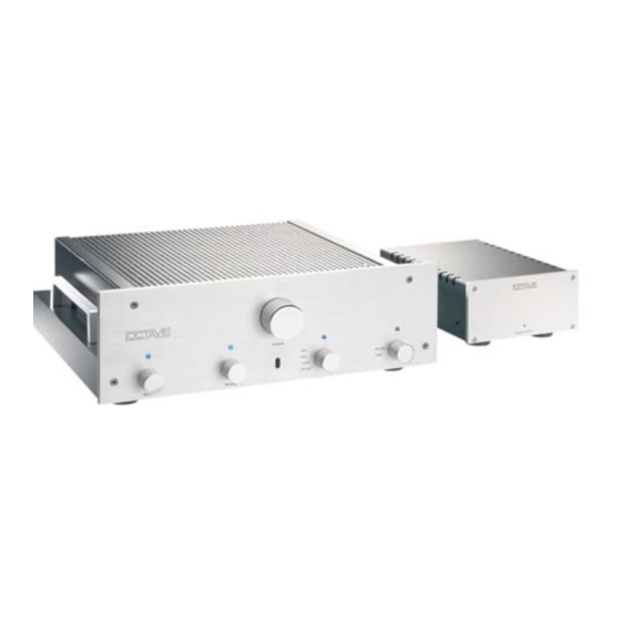
4. OPERATION - Front panel Stand by switch The LED above the switch burns, if the unit is turned on. If the preamplifier is turned off, it remains in the stand by mode, which means, that parts of the electronic are still working. If the unit will not be used for a longer period, it should be turned off with mains power switch of the preamp-filter I. - Page 8 4. OPERATION - Front panel Input selector rotary-switch If the LED above the input selector burns (tape-source-switch in position ″source″), the here chosen source is played back at the output of the preamplifier: disc: playback CD aux: input for an additional line unit tuner: playback tuner or DSR phono:...
-
Page 9: Rear Panel
5. CONNECTIONS: Rear panel Subsonic-filter switch turn switch left: off; turn switch right: on Phono-selector The toggle switch activates either MM input or MC input. Two turntables can be connected at the same time. Input MC input for turntables with MC-systems GND (ground) cable Connection for the ground cable of the turntable (if existing). -
Page 10: External Power Supply
6. EXTERNAL POWER SUPPLY Power Supply Indicator LED The LED illuminates when the unit is switched on. Description The HP 500 MK3 is equipped with a specially designed external power supply incorporating highly effective mains and high frequency filters. To provide maximum shielding from electromagnetic interference, the unit is housed in a separate case. - Page 11 6. POWER SUPPLY REAR Power Supply Serial No......Mains: 230 VA/0,5A 115 VAC/1A made in Germany On/off switch Switch the unit off if you do not intend to use the preamplifier for some time. AC input (three-pin receptacle): A power cable is supplied with your preamplifier. Fuse holder for T 0,63 AL fuse.
-
Page 12: Changing The Batteries
7. IR REMOTE CONTROL FOR VOLUME Front panel screws (Two M3 Philips countersunk screws) Keypad Battery compartment for two AA 1.5 V batteries Volume button + button: louder; - button: quieter Infrared transmitter Point the transmitter at the amplifier. The remote will operate up to a distance of about 8 metres. -
Page 13: Phono Mm/Mc Option
8. PHONO MM/MC OPTION The role of the phono preamplifier A record player is an electro-mechanical device. Music signals are "pressed" into the grooves in the record, and these are physically tracked and read by the pickup cartridge. In order to get the entire 20 Hz - 20 KHz frequency range into the grooves, the frequency response has to be shaped by lowering the level of the low frequency information and raising the level of the high frequency information. -
Page 14: Adjusting The Mc Input
8. ADJUSTING the MC input Before you can adjust the MC input, you need to remove the grille from your preamplifier (see Removing the grille). Slider switches for MC input impedance Left channel Right channel Switch 1 – 4 Switch 5 - 8 Switch option Switch Switch... -
Page 15: Tube Layout
9. TUBES 9.1. Tube layout phono-board power supply board line-board Line board: ECC 82 / 12 AU 7 EF 184 Phono board: ECC 83 / 12 AX 7 ECC 81 / 12 AT 7 ECC 88 / 6922... -
Page 16: Removing The Grille
9.2. REMOVING THE GRILLE First, switch the unit off and remove the mains plug from its wall socket. Remove the two Allen bolts located at the top left and right of the front panel using a size 4 Allen key. Insert a Philips no. -
Page 17: Replacing Tubes
9.3. REPLACING TUBES Please use only original OCTAVE replacement tubes. These have been selected and tested for use in our amplifiers. Important! Changing tubes is a job for a qualified technician! Switch off the preamplifier, unplug the power cord from the wall socket, and allow the unit 10 minutes to cool down. -
Page 18: Troubleshooting
10. TROUBLESHOOTING Noise and hum Hum in an audio system is often caused by several system components being grounded separately. It is particularly common in systems containing tuners, VCRs or satellite receivers connected to an aerial, where a hum loop may be introduced via the aerial input. Although the HP 500 MK3 is also grounded, it is equipped with a special technology that reliably prevents ground loops. -
Page 19: Technical Data And Dimensions
11. TECHNICAL DATA AND DIMENSIONS Line stage Gain high 17.5 dB = 7.5 Frequency response 3 Hz - 300 kHz 1.5 dB Total harmonic distortion 0.001% at 3V / 7.5 kOhm Signal-to-noise ratio: high gain - 92 dB Channel separation 65 dB 1 kHz Crosstalk rejection between inputs - 86 dB 10 kHz... - Page 20 11. TECHNICAL DATA AND DIMENSIONS Overall dimensions of the preamplifier in mm ca. 460 Volume Disc Source Tuner Tape Phono FEATURES The HP 500 MK3 is fitted as standard with two RCA phono outputs and one optional XLR outputs. The XLR output is transformer-coupled and galvanically isolated. The HP 500 MK3 phono has separate inputs for MM/MC.
Need help?
Do you have a question about the HP500MK3 and is the answer not in the manual?
Questions and answers