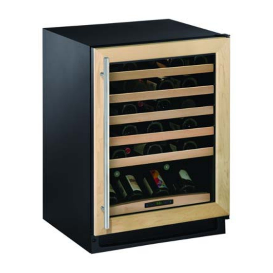
U-Line WINE CAPTAIN 2115R Install Manual
2000 series refrigerator / freezer beverage centers wine captain models
Hide thumbs
Also See for WINE CAPTAIN 2115R:
- Service manual (180 pages) ,
- Use and care manual (20 pages) ,
- Installation instructions manual (6 pages)
Summary of Contents for U-Line WINE CAPTAIN 2115R
- Page 1 ® INSTALL GUIDE 2000 SERIES REFRIGERATOR / FREEZER BEVERAGE CENTERS WINE CAPTAIN® Models 2175WCC 2175BEVC 2175RF 2115WC 2115R The Built-In Undercouter Leader Since 1962 U-LINE.COM...
-
Page 2: Table Of Contents
1 Table of Contents Safety Precautions Safety Alert Definitions...1 General Precautions ...1 Inspect & Plan Product Registration ...2 Models Covered...2 Tools / Material Required ...2 Exterior Cleaning ...2 Black and White Models:... 2 Stainless Models:... 2 Prepare Site Electrical Specifications ...3 Cut-Out Dimensions...3 2115 Series ... -
Page 3: Safety Precautions
• Proper installation procedures must be followed when completing an installation or relocation of a unit. Consult the installation guide before any installation begins. U-Line contact information appears on the rear cover of this guide. • This unit requires connection to a dedicated 15 Amp... -
Page 4: Inspect & Plan
3 Inspect & Plan Product Registration You have received a carton containing your U-Line Refrigerator, Refrigerator Freezer, Beverage Center or Wine Captain® unit with a package inside containing a Use and Care Guide, a Product Registration Card, and a water line kit. Please complete and mail the Product Registration Card or register online at www.U-... -
Page 5: Prepare Site
4 Prepare Site Your U-Line product has been designed for either free-standing or built-in installation. When built-in, your unit does not require additional air space for top, sides, or rear. However, the front grille must NOT be obstructed and clearance is required for an electrical connection in the rear. -
Page 6: Product Dimensions
2115R 2115WC(OL) & 2175RC 5 Product Dimensions Series 2115R Series 2115WC / 2115WCOL Series 21175RC/RCG/RF Series 23-1/4" 23-1/16" 23-1/4" 34-1/8" 34-1/8" 34-1/8" 3-13/16” 15" 3-13/16” 15” 3-13/16” 24" 2115R Black / White Models 2115WCS Stainless Steel Models 2175R(C)(F) Black and White Models 23-1/8”... -
Page 7: 2175Bev & 2175Wc 2275Zwc Series
2175BEVC Series 23-1/4” 34 - 1/8" 3 - 13/16” 23 15-16” 2175BEVCS Stainless Steel Models 22-5/8" 34 - 1/8” 3 - 13/16” 23 15-16” 2175BEVCOL Wood Overlay Models 2175WCC Series 23-1/4” 34 - 1/8" 3 - 13/16” 24" 2175WCCS Stainless Steel Models 22-5/8"... -
Page 8: Door Swing Dimensions
6 Door Swing Dimensions 2115R Models Wall 1/4" Min. 2" Min. 21" 16-1/2" Door Swing Door Swing Black and White Models 2115WC Models Wall 1/4" Min. 2" Min. 21" 16-1/2" Door Swing Door Swing Black, White and Wood Overlay 2175R(F) & 2275WC Models Wall 1/4"... -
Page 9: Self-Closing Doors
The top hinge hardware will be reinstalled on the bottom of the opposite side of the cabinet. The bottom hinge hardware will be reinstalled on the top of the opposite side of the cabinet. U-Line Self-Closing Door Alignment and Reversal... - Page 10 4. Hold door to keep it from falling. 5. Reinstall hinge screw pin (1) into top hinge using a Phillips screwdriver. Align and adjust the door: Align and adjust the door, see DOOR ALIGNMENT AND ADJUSTMENT above. U-Line Self-Closing Door Alignment and Reversal NOTCH...
-
Page 11: Wood Trim Finishing
5. Lightly sand and reapply if desired. Allow the final coat to dry for 24 hours before reinstalling the trim to the cabinet interior parts. U-Line Wood Trim Finishing IMPORTANT IMPORTANT ® ®... -
Page 12: Door Panel Installation Custom 1/4'' Thick Door Panel Insert
7. Install two small screws removed in Step 3. 8. Starting at the corners and working inward, push door gasket into place on door. Height 9. Place door on bottom hinge pin and install upper hinge screw. 27 11/16” 27 11/16” U-Line Door Panel Installationl IMPORTANT IMPORTANT... -
Page 13: Overlay Frame
10 Overlay Frame Frame Preparation 2115WCOL 2175WCCOL & 2175BEVCOL Models Only An overlay frame covers the door frame to give a built-in appearance. Appropriate hardware and a copy of these instructions will be included with the unit. IMPORTANT IMPORTANT The thickness of the overlay panel must be 3/4” Right-hand isometric view shown. -
Page 14: Prepare The New Overlay Panel
Prepare The New Overlay Panel IMPORTANT IMPORTANT The overlay door panel must not weigh more than 20 lbs. The thickness of the door panel must be 3/4” 1. Place a towel, or similar, soft non-marking material out on a flat clean surface. -
Page 15: Assembling Door To Cabinet
TAPE TOP OF OVERLAY 6. Use the door frame holes as a guide to lightly punch pilot holes for the #6x1” pan head screws 7. Attach the door to the overlay using #6x1” wood screws. IMPORTANT IMPORTANT If you decide to drill pilot holes, remove the wood overlay from the door, and do not use a drill larger then 7/64”. -
Page 16: Leveling Information
11 Installation Leveling Information It is recommended that the unit is level. 1. Use a level to check the levelness of the unit from front to back and from side to side. Level should be placed along top edge and side edge as shown 2. -
Page 17: Service Information
E-mail: onlineparts@u-line.com ABOUT U-LINE Building on 45 years, U-Line has captivated those with an appreciation for the finer things with exceptional design, inspired innovations and attention to even the smallest details. U-Line is synonymous with premium built-in undercounter ice making, refrigeration and wine storage appli- ances, the U-Line Corporation is committed to luxury under the counter.


Need help?
Do you have a question about the WINE CAPTAIN 2115R and is the answer not in the manual?
Questions and answers
looking for the control panel, off/on and temperature switch. Cannot turn it off and cannot get temperature control working u-2115wcs-01. it shows blank lines for temp and the power will not go off. Compressor not working