Table of Contents
Advertisement
Installation, Operation and Maintenance
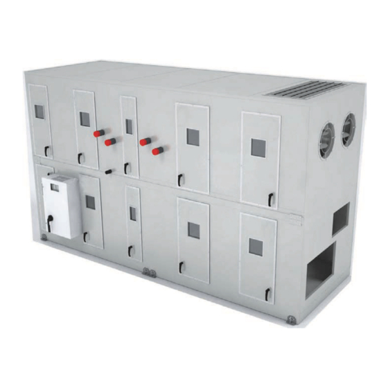
Performance Climate Changer™ Air
Handlers
Model PSCA
Only qualified personnel should install and service the equipment. The installation, starting up, and servicing of
heating, ventilating, and air-conditioning equipment can be hazardous and requires specific knowledge and training.
Improperly installed, adjusted or altered equipment by an unqualified person could result in death or serious injury.
When working on the equipment, observe all precautions in the literature and on the tags, stickers, and labels that are
attached to the equipment.
April 2020
SAFETY WARNING
CLCH-SVX013B-EN
X-39641306001
Advertisement
Table of Contents

Related Manuals for Trane Performance Climate Changer PSCA


Summary of Contents for Trane Performance Climate Changer PSCA
- Page 1 Installation, Operation and Maintenance Performance Climate Changer™ Air Handlers Model PSCA SAFETY WARNING Only qualified personnel should install and service the equipment. The installation, starting up, and servicing of heating, ventilating, and air-conditioning equipment can be hazardous and requires specific knowledge and training. Improperly installed, adjusted or altered equipment by an unqualified person could result in death or serious injury.
- Page 2 (Global Harmonized System of Classification and compounds have the same potential impact to the Labeling of Chemicals) guidelines for information on environment. Trane advocates the responsible handling of allowable personal exposure levels, proper all refrigerants-including industry replacements for CFCs respiratory protection and handling instructions.
- Page 3 Copyright This document and the information in it are the property of Trane, and may not be used or reproduced in whole or in part without written permission. Trane reserves the right to revise this publication at any time, and to make changes to its content without obligation to notify any person of such revision or change.
-
Page 4: Table Of Contents
Table of Contents Introduction Hood Installation ....24 ......6 Nameplate Stacked Outdoor Unit Assembly . - Page 5 Table of Contents Humidifier Piping and Connections ..49 Fan Motor Inspection ....76 Remodel, Retrofit, or Replacement Filters ..49 .
-
Page 6: Introduction
Note: The unit serial number and order number is manual to minimize installation and startup difficulties. required when ordering parts or requesting service for a Trane air handler. Nameplate Each Performance air handler section includes one or more nameplate/label, which identifies the type of section Figure 1. -
Page 7: General Information
Pre-Packaged Solutions for Controls The Performance Climate Changer air handler is designed If the air handler has been selected using one of Trane’s for a variety of controlled-air applications. The basic unit pre-packaged solutions options for controls, there are a... -
Page 8: Wiring
The fan motor nameplate includes a wiring diagram. If there are any questions concerning the wiring of the motor, write down the information on the motor nameplate and contact your local Trane sales office. CLCH-SVX013B-EN... -
Page 9: Pre-Installation
Performance air handlers ship as a complete unit or in carrier and consignee. individual sections to be field assembled. Indoor air Notify your Trane sales representative of the damage handler sections are stretch-wrapped or shrink-wrapped and arrange for repair. Do not attempt to repair the unit before shipping. -
Page 10: Long-Term Storage
Pre-Installation necessary, several things must be done to prevent damage: NOTICE Note: Keep the equipment on the original wooden blocks/ Microbial Growth! skid for protection and ease of handling. The floor or foundation must be level and the • Select a well-drained area, preferably a concrete pad or condensate drain at the proper height for proper coil blacktop surface. - Page 11 Pre-Installation 1. Verify that the roof structure can adequately support Figure 2. Cross section of typical curb installation on the combined weight of the unit and curb assembly. new construction 2. Ensure that the selected installation location provides sufficient service and operational clearances. Screw securing roof 3.
-
Page 12: Dimensions And Weights
NEC requirements. For specific dimensional and weight information, refer to the unit submittals. The dimensions and weights in this manual are approximate. Trane has a policy of continuous product and product data improvement and reserves the right to change design and specifications without notice. -
Page 13: Fans/Motors
>18 point terminal strip 36.00 Access Fans/Motors Note: Trane has a Precision Motor™ option for direct- VFD Weights drive plenum fans. This offering takes a general With the exception of motorized impellers, fan weight purpose motor and re-rates the motor for higher does not include VFD weight. -
Page 14: Installation - Mechanical
Installation - Mechanical Lifting and Rigging Before preparing the unit for lifting, estimate the approximate center of gravity for lifting safety. Because of placement of internal components, the unit weight may be Remove Shipping Tie-Downs unevenly distributed, with more weight in the coil and fan Prior to unit placement, remove the shipping tie- areas. -
Page 15: Lifting Hoods And Pipe Cabinets
Do not use a fork lift on air handlers or subassemblies that do not have end cleat. Improper use of fork lifts could result in equipment damage. Trane is not responsible for equipment damage resulting from improper fork lifting practices. -
Page 16: Unit Placement And Assembly
If the air handler ships in subassemblies or in individual local Trane representative before proceeding. sections, some assembly is required, including: Following the order of the sections on the unit submittals •... -
Page 17: Removing The Shipping Skid
Installation - Mechanical Ceiling Suspension Figure 10. Piers located in each corner and spaced evenly every four feet WARNING Risk of Unit Dropping! Do not use mounting legs for ceiling suspension, external isolation, or unit support during module placement. Mounting legs are designed only to secure the unit to the floor, housekeeping pad, or platform. -
Page 18: Shipping Gussets
(see Figure 14). See submittal documentation for unit thoroughly before contacting your Trane sales lifting lug size. representative to report missing items. • Bolt shipping splits together. - Page 19 Installation - Mechanical To assemble the unit: Figure 19. Stacked unit assembly 1. Locate the mounting hardware and gasket material. 2. All shipping supports and crating on the face of the sections must be removed and discarded to permit proper fit-up and sealing of the surfaces. Remove any shipping bolts located on the mounting surfaces of the sections (see Figure...
- Page 20 Installation - Mechanical Figure 21. Horizontal section-to-section high voltage Figure 23. Roof alignment (indoor unit only) quick connects 5. Assemble and seat connections per color code. 12. In addition, an adjustment can also be made to the height of the roof of either subassembly. At the center Figure 22.
- Page 21 Installation - Mechanical 13. Bolt the unit base frames together using bolts or Figure 25. Adjust height of roof by loosening screws threaded rod provided (see Figure 26). 14. Use straps and come-alongs to compress the gasketing and pull the sections together along the height of the unit.
-
Page 22: Pipe Cabinet Installation
Installation - Mechanical 15. Install the section-to-section screws inserting the appropriate screws through the overlapping flanges seam cap that is to be installed over the section-to- using a powered impact gun and taking care not to section seams. Factory-supplied butyl tape must be strip the screws. - Page 23 Installation - Mechanical Figure 28. Pipe cabinet installation Cabinet Detail See Cabinet Detail See Detail A See Detail B Armacell 1-in. x 7.5-in. x 10-ft. roll Detail B Detail A White Butyl tape .375-in. X .375-in. White Butyl tape .375-in. X .375-in. Armacell 1-in.
-
Page 24: Hood Installation
Installation - Mechanical Figure 29. Pipe cabinet installation details See Detail G Screw; Detail C 0.375-16 x 1.250 Hex cap Plate lug replacement Detail D See Details C, D, E, F Plate lug replacement 0.500-13 x 10.5-in. 1/2-in. washer flat 1/2-in. -
Page 25: Stacked Outdoor Unit Assembly
Installation - Mechanical to be connected to the air handler by the installing Note: It is required that the hoods be sealed to the unit contractor. See Figure using factory-provided butyl/caulk tape. Figure 30. Hood installation Detail A Butyl caulk tape 1.00 W x .125T AHU outdoor roof Butyl caulk tape... - Page 26 Installation - Mechanical Figure 31. Stacked unit assembly Remove lugs from upper baserail prior to installing Detail A stacked unit bracket (1) Gasket: 1.00T x 4.00W (3) Screw: 0.313-18 x 0.875 sheetmetal Part# X25240049010 (2) Bracket: stacked unit (4) Screw: (2) Bracket: 10-16 x 0.750 stacked unit...
- Page 27 Installation - Mechanical Flashing Installation 2. Apply Butyl tape (Item 8) to direction-of-airflow flashing (Item 12) and secure to base rails with screws For additional information, see “Flashing Installation (Item 4). Start at corners to ensure tight corner seams. Notes,” p. Apply caulk (Item 14) to create water-tight seal (see For hood installations, see “Install flashing and hood,”...
- Page 28 Installation - Mechanical Flashing Installation for Stacked Unit With Figure 34. Flashing installation location Second Level Shorter Than First Detail A 1. Ensure that first level roof section is properly sealed Upper panel with Butyl tape (item 8) and/or caulk (Item 14) at the .060 gap between bottom of panel and ends.
- Page 29 Installation - Mechanical 5. For units with a two-piece roof, additional sealing is Figure 39. Apply caulk to seal. required in the middle where the first level roof sections meet with second level baserail. Seal vertical Before installing flanges of roof with caulk (Item 8) prior to installing flashing apply caulk flashing.
-
Page 30: External Raceway Assembly
Installation - Mechanical Install flashing and hood 4. Secure hood support angles (Item 16) to hood support brackets (Item 15) and to the hood side panels with 1. See Figure 41. Secure two hood support brackets (Item screws (Item 17). 15) to base rail with screws (Item 17). -
Page 31: Seismic Application Requirements
Requirements Grade to Roof Mounted Non-Isolated Steel dunnage/steel curb. Air handling equipment manufactured by Trane is capable of structurally and operationally withstanding the seismic 3/8-inch diameter ASTM A325 or SAE grade 5 bolts response criteria as required by the International Building... -
Page 32: Stacked Design
Installation - Mechanical Table 7. Anchor requirements for non-stacked units Seismic Attachment System Attachment Equipment Restraint method weight (lbs.) model Qty per tag Method Anchor: Hilti HDA-P Dia.: M12 x 125/50 Floor mounted 2 per mounting 1.483 45 psf maximum Bolt down Embed.: 4.922 inches (concrete) -
Page 33: Ceiling Suspended Units
Installation - Mechanical Ceiling Suspended Units Figure 44. Seismic anchor pattern (0<=Sds<=1.85) AHU Plan View The details for the suspension system, including the steel Spacing <= 46 inches* Staggered anchor members used to support the bottom of the unit, will need bolt patterns to be determined by working directly with The VMC Group. -
Page 34: Pipe Cabinet Installation
Installation - Mechanical Pipe Cabinet Installation 1. Remove the fasteners from the top of the nested U channel. Nested U channels and L angle have to be removed to 2. Remove the U channel from the unit base L angle and install the pipe cabinet to the unit and reinstall per the pipe cabinet base L angle. - Page 35 Installation - Mechanical 4. Attach the unit base L angle from the pipe cabinet to the 6. Locate the pipe cabinet in place, and reinstall the U unit base rail. See Step 4 in Figure 46 channel to the pipe base L angle and reinstall the top U channel to the nest (see Step 1, Figure 45).
-
Page 36: Component Installation
Component Installation Component Installation The components in the air handler may have installation requirements that could affect the unit’s performance. WARNING Hazardous Service Procedures! Dampers The maintenance and troubleshooting procedures recommended in this manual could result in exposure Dampers are factory-installed and adjusted and can be to electrical, mechanical or other potential safety found in mixing box sections. -
Page 37: Motor Removal Rail
A final filter is placed after the fan. • A pre-filter is placed before the fan. Note: Cartridge and bag filters provided by Trane are fitted with a 7/8-inch header that fits in the filter track. If using filters supplied by another manufacturer, filters should be purchased with a 7/ 8-inch header. -
Page 38: Duct Connections
Component Installation obstruct the damper opening (see Figure 50 Figure 49. Filter block-off placement Figure 51). Note: Damper blades should be checked for proper operation from full-open to full-closed position before unit start up. Damper blade positioning may have changed due to shipping and handling vibrations. -
Page 39: Discharge Plenum Connections
(see Figure 53 Figure 54). Figure 52. Field-supplied duct connection to AHU bottom supply/return air opening Bottom supply/ return airflow Typical Trane air handler base Field-supplied Typical Trane rigid duct air handler base Field-supplied rigid duct Figure 53. -
Page 40: Bell Mouth Discharge Connections
Component Installation Bell Mouth Discharge Connections Figure 56. Securing round duct to bell mouth outlet Round duct connections to be fastened to plenum fan and discharge plenum sections with bell mouth discharge openings should be sized to attach to the casing or directly to the bell mouth fitting. -
Page 41: Other Connections
Component Installation Other Connections Access, filter, and other sections may have open inlets with a 2-inch (sizes 3-120) panel frame for connecting the ductwork. If the duct is lined, it is important the insulation does not obstruct the opening of the section. Figure 58. -
Page 42: Piping And Connections
Pitch the connection lines • Support all piping independently of the coils. horizontal or downward toward an open drain. Trane • Provide swing joints or flexible fittings on all recommends installing a plug to facilitate cleaning of the connections that are adjacent to heating coils to trap. -
Page 43: Steam Coil Piping
Piping and Connections Table 9. Drain pan trapping for negative and positive pressure applications Negative pressure Positive pressure Drain pan trapping for section Drain pan trapping for section under negative pressure under positive pressure L = H + J + pipe diameter where: L = H + J + pipe diameter where: H = 1 inch for each inch of negative H = 1/2 inch (minimum) - Page 44 Use bucket traps only when the supply steam is not damage. modulated and is 25 psig or higher. Note: Trane steam coils require a minimum of 2 psi of To prevent coil damage, complete the following pressure to assure even heat distribution.
-
Page 45: Water Coil Piping
Piping and Connections Water Coil Piping Figure 63. Typical piping for stacked water coils Type 5A, 5W, D1, W, UW, TT, P,2, P4, and P8 water coils are self-venting only if the water velocity exceeds 1.5 feet per second (fps) in the coil tubes. Type D2, UA, UU, and WD water coils are self-venting only if the water velocity exceeds 2.5 fps in the coil tubes. -
Page 46: Refrigerant Coil Piping
Piping and Connections Refrigerant Coil Piping Figure 64 illustrates an example of a split-system component arrangement. Use it to determine the proper, relative sequence of the components in the refrigerant Note: Refer to for information on handling refrigerants. lines that connect the condensing unit to an evaporator coil. -
Page 47: Liquid Lines
(MCHE), solenoid valves isolate the distributor refrigerant from the evaporator during the off cycles. Trim solenoids cannot be used with MCHE. Note: Trane condensing units with MCHE no longer Coil employ pump-down, but isolation solenoids are required. The suggested solenoid uses a 120-volt... -
Page 48: Suction Lines
Components Trane now has many years of experience in the successful use of equipment without hot gas bypass in commercial Installing the suction line requires field installation of comfort-cooling applications. To prevent evaporator these components: a filter, access port, and a Frostat™... -
Page 49: Humidifier Piping And Connections
All accessories listed above will be on the packing slip. Report any shortages immediately. If accessories have Remodel, Retrofit, or been damaged in transit, notify Trane and file claim with Replacement the transportation company. If your order covers more than one package, segregate complete assembly. - Page 50 For and for their compatibility with the newer POE oil. specific handling concerns with R-410A, please contact your local Trane representative. • For the best performance and operation, the original mineral oil should be removed from the components Every part of an existing split system needs to be analyzed of the system that are not being replaced.
-
Page 51: Field-Installed Evaporator Piping
Piping and Connections Field-Installed Evaporator Piping Figure 67. Typical single-circuit condensing unit: evaporator coil with one distributor 1. Pitch the liquid line slightly—1 inch/10 feet —so Evaporator Coil with Standard Circuiting that the refrigerant drains toward the Suction line evaporator. 2. - Page 52 Piping and Connections Figure 69. Typical single-circuit condensing unit: evaporator coil with four distributors 1. Pitch the liquid line slightly—1 inch/10 feet —so Evaporator Coil with Horizontal-Split (Standard) Circuiting that the refrigerant drains toward the evaporator. Suction line Thermal expansion valves (TXV) 2.
- Page 53 Piping and Connections Figure 70. Typical dual-circuit condensing unit: evaporator coil with two distributors Evaporator Coil Suction line with Horizontal-Split (Standard) Circuiting (circuit 2) Liquid line (circuit 2) Sight glass Solenoid Distributor valve Suction line (circuit 1) Liquid line (circuit 1) Thermal Filter drier expansion...
- Page 54 Piping and Connections Figure 71. Typical dual-circuit condensing unit: evaporator coil with four distributors 1. Pitch the liquid line slightly—1 inch/10 feet —so Evaporator Coil with Horizontal-Split (Standard) Circuiting that the refrigerant drains toward the Suction line evaporator. (circuit 2) Liquid line Thermal expansion 2.
- Page 55 Piping and Connections Figure 72. Typical dual-circuit condensing unit: evaporator coil with eight distributors 1. Pitch the liquid line slightly—1 inch/10 feet —so Evaporator Coil with Horizontal-Split (Standard) Circuiting that the refrigerant drains toward the Suction line evaporator. Thermal expansion valves (TXV) 2.
-
Page 56: Installation - Electrical
Follow proper lockout/ tagout procedures to ensure the power cannot be inadvertently energized. For variable frequency drives or other energy storing components provided by Trane or others, refer to the appropriate manufacturer’s literature for allowable waiting periods for discharge of capacitors. -
Page 57: Quick Connects
Installation - Electrical • Connect control valves, if ordered, to the valve jack Figure 76. Controller - externally mounted provided as part of the unit wiring harness. The valve jack is typically located at the air-leaving side of the coil connection inside the casing panel. - Page 58 Installation - Electrical unit and motor connection diagrams are provided on the VFD if Trane-provided, or refer to the motor nameplate. Fractional horsepower motors may be factory connected to a terminal box on the unit. If this construction is provided, the installer should complete field wiring to this connection box.
-
Page 59: Typical Wiring Schematics
Installation - Electrical Typical Wiring Schematics Figure 80. Typical VFD wiring schematic 1PD1 Supply fan 1CB11 1K40 Splice 1B,C,D 4A,B 1K40 Customer Splice 2B,C,D 5A,B supplied power 1K40 Splice 3B,C 6A,B Attach earth 101E ground 102E Ret/Exh 103E 1K41 1F40 U/T1 1K41 1F41... - Page 60 Installation - Electrical Figure 81. Typical UV light schematic Additional switches (if required) wired in series Customer supplied 120VAC power Connectors required for shipping splits BLK 7 GRN 1 WHT 2 WHT 8 BLK 3 GRN 9 10 GRN BLK 4 WHT 5 GRN 6 To additional rows of...
- Page 61 Installation - Electrical Figure 82. Schematic for customer-supplied power for GFCI and lights/switch 3GFR1 2TB4 Dedicated GFCI customer suppoled power (115V) Attach earth ground Custom supplied power (115V) Attach earth ground 115V 115V Lighting Transformer Fuses Fuse Voltage 2F73 2F74 2F75 2F76 2F73...
-
Page 62: Controls Interface
The portable operator display is used for temporary security, see the Tracer TD7 Display for the Tracer UC600 connection to and operation of Trane UC600 controller. Programmable Controller Installation, Operation, and With the portable operator display, you can monitor data, Maintenance guide (BAS-SVX50C-EN). - Page 63 Controls Interface operation of the air handler without disruption to the operating conditions of the unit. When servicing of the unit is complete, close the cover plate on the service module to eliminate any air leakage path. CLCH-SVX013B-EN...
-
Page 64: Start-Up
For variable frequency drives Coil-Related Checks or other energy storing components provided by Trane or others, refer to the appropriate manufacturer’s literature for allowable waiting periods for discharge of NOTICE capacitors. -
Page 65: Motor-Related Checks
Units shipped with an optional variable frequency drive components, perform these tasks. Failure to follow all (VFD) are preset and run-tested at the Trane factory. If a safety precautions could result in rotating components cutting and slashing technician which could result in problem with a VFD occurs, ensure that the programmed death or serious injury. - Page 66 For variable frequency drives 40 - 125 or other energy storing components provided by Trane 0.5 - 10 or others, refer to the appropriate manufacturer’s literature for allowable waiting periods for discharge of 15 - 125 capacitors.
-
Page 67: Airflow Measuring Systems
Start-Up Airflow Measuring Systems can be converted to represent airflow (cfm or L/s) using the formula below and Table Traq™ Dampers volts 2 – Airflow = k (cfm @ 10V) ------------------------------ Traq dampers are low-leak dampers that modulate and ... - Page 68 Start-Up Trane utilizes AMCA certification for airflow Table 14. Traq Damper Flow Calculations measuring stations. Trane certifies that the Traq Peak Total CFM @ L/S @ Traq damper herein is licensed to bear the Damper Velocity Area 10VDC 10VDC AMCA seal. The ratings shown are based on Size (In.) Qty...
-
Page 69: Fan Inlet Airflow Measuring System
Note: This type of system is different than a total pressure or thermal dispersion system. As such, the Trane air handlers use a 0-5 inch, 0-20 inch, or 0-30 inch calculations will be different. w.g. range transmitter as standard. To sufficiently cover... -
Page 70: Constant K Factor
Start-Up Maintenance Constant K Factor For a typical HVAC environment - especially with upstream The constant K factor is unique for each fan and is filtration - there should be little to no required primarily a function of the area and other geometric maintenance. -
Page 71: External Insulating Requirements
Start-Up External Insulating Requirements When a single transmitter is supplied in a multiple fan system, one or more fans will be brought back to the transmitter as a manifold and the airflow will represent the The following areas should be specifically addressed, as total airflow for the system. -
Page 72: Routine Maintenance
Routine Maintenance WARNING WARNING Hazardous Service Procedures! Rotating Components! The maintenance and troubleshooting procedures The following procedure involves working with recommended in this manual could result in exposure rotating components. Disconnect all electric power, to electrical, mechanical or other potential safety including remote disconnects before servicing. -
Page 73: Cleaning Porous Surfaces
Routine Maintenance 9. Replace all panels and parts and restore electrical power to the unit. WARNING 10. Be careful any contaminated material does not contact Hazardous Chemicals! other areas of the unit or building. Properly dispose of Coil cleaning agents can be either acidic or highly all contaminated materials and cleaning solution. -
Page 74: Refrigerant Coils
Water coil winterization procedures consist primarily of Hazardous Chemicals! draining water from the coil before the heating season. Trane recommends flushing the coil with glycol if coils will Coil cleaning agents can be either acidic or highly be exposed to temperatures below 35 degrees. -
Page 75: Moisture Purge Cycle
Routine Maintenance 3. Fill and drain the coil several times with full strength glycol so that it mixes thoroughly with the water WARNING retained in the coil. No Step Surface! 4. Drain the coil out as completely as possible. Do not walk on the sheet metal drain pan. Walking on 5. -
Page 76: Inspecting And Cleaning Fans
5. Immediately rinse the affected surfaces thoroughly to prevent air bypass. If using filters not supplied by with fresh water and a fresh sponge to prevent Trane, apply foam gasketing to the vertical edges of potential corrosion of metal surfaces. the filter. -
Page 77: Moisture Eliminator
Routine Maintenance Moisture Eliminator 4. Wipe down each bulb with a clean cloth and alcohol. Avoid touching the bulb with bare hands as skin oils can accelerate future glass soiling and degrade the The moisture eliminator in the outside air intake hood bulb performance. - Page 78 Routine Maintenance federal guidelines. Check all regulations before disposing of bulbs to assure you have met all requirements. Refer to the MSDS sheet from the bulb manufacturer for additional disposal, handling and safety information. After replacing bulbs, close and latch all unit panels and reenergize power to the lights.
-
Page 79: Troubleshooting
Troubleshooting This section is intended to be used as a diagnostic aid only. For detailed repair procedures, contact your local Trane service representative. WARNING Hazardous Service Procedures! The maintenance and troubleshooting procedures recommended in this manual could result in exposure to electrical, mechanical or other potential safety hazards. - Page 80 Troubleshooting Table 17. Air handler troubleshooting recommendations Symptom Probable Cause Recommended Action Incorrect airflow Check fan operating condition. Check sensing bulb temperature. Expansion valve is not operating properly or is sized Verify valve operation. incorrectly Verify proper valve size. Incorrect refrigerant charge Verify refrigerant charge and adjust if necessary.
- Page 82 For more information, please visit trane.com or tranetechnologies.com. Trane has a policy of continuous product and product data improvement and reserves the right to change design and specifications without notice. We are committed to using environmentally conscious print practices.
Need help?
Do you have a question about the Performance Climate Changer PSCA and is the answer not in the manual?
Questions and answers