Table of Contents
Advertisement
Advertisement
Table of Contents

Related Manuals for LI-COR Odyssey CLx


Summary of Contents for LI-COR Odyssey CLx
- Page 1 Odyssey® CLx Operator’s Manual...
- Page 3 CE Marking: This product (model number 9140) is a CE-marked product. For conformity information, contact LI-COR Support at http://www.licor.com/biotechsupport. Outside of the U.S., contact your local sales office or distributor. 德 CLX Odyssey CLx Imager Part Name Toxic and Hazardous Substances or Elements...
- Page 4 Notes on Safety LI-COR products have been designed to be safe when operated in the manner described in this manual. The safety of this product cannot be guaranteed if the product is used in any other way than is specified in this manual. The ®...
- Page 5 WARRANTY OF ANY KIND WITH REGARD TO THIS MATERIAL, INCLUDING, BUT NOT LIMITED TO THE IMPLIED WARRANTIES OF MERCHANTABILITY AND FITNESS FOR A PARTICULAR PURPOSE. LI-COR shall not be liable for errors contained herein or for incidental or consequential damages in connection with the furnishing, performance, or use of this material.
-
Page 6: Table Of Contents
Odyssey® Table of Contents Imager Chapter 1: Installation and Safety Information Safety Considerations Laser Safety Safety Interlocks Placement in the Laboratory Ambient Laboratory Conditions Instrument Ventilation Space Requirements Moving the Instrument Chemical Safety Electrical Considerations Power Cords Power Switch Fuse Information Routine Maintenance Networking Cables Chapter 2: System Overview... - Page 7 Using Gels Using Microplates Using the MousePOD Accessory Positioning Membranes and Gels Positioning Microplates Obtaining Technical Support Chapter 4: Appendix Specifications Imaging System Operating Specifications Embedded Firmware Source Code...
-
Page 9: Chapter 1: Installation And Safety Information
Odyssey CLx lid is opened. The label shown in Figure 1-3 is affixed to the inside of the Odyssey CLx case at two locations; one near the laser/microscope assembly scanning bed, and the second on the cover that is used to seal the above mentioned assembly. - Page 10 See "Rear Panel" on page 8 for the location of the labels in Figure 1-1 and Figure 1-2. The label in Figure 1-3 is affixed to the inside of the Odyssey CLx Imager case at two locations; one near the laser/microscope assembly scanning bed, and the second on the cover that is used to seal the above mentioned assembly.
-
Page 11: Safety Interlocks
Odyssey CLx Imager. Ambient Laboratory Conditions Place the Odyssey CLx Imager away from external heat sources (furnaces, windows, etc.). Additional heating can cause high temperatures within the enclosure. Place the instrument away from sinks or other sources of water that pose a shock hazard. Recommended operating conditions are 15-35 °C and a dew point not greater than 20 °C to prevent condensation on the laser/microscope assembly... -
Page 12: Space Requirements
Space Requirements The Odyssey CLx Imager requires an area approximately 37 H x 53 W x 62 D cm (15 x 21 x 24.5 inches). With the hood fully open, the Odyssey CLx requires 74 cm (29”) of vertical clearance. -
Page 13: Electrical Considerations
Do not locate the Odyssey CLx where the power cord will be walked on or exposed to water or chemical spills. The Odyssey CLx draws at most 4 amperes at 120V. If an extension cord is used, make sure the total of the ampere ratings on the instruments plugged into the extension cord does not exceed the extension cord ampere rating. -
Page 14: Networking Cables
Chapter 1: Installation and Safety Information maintained. LI-COR Biosciences recommends that you routinely inspect the system and the scanning surface. The following are some general maintenance guidelines: Wipe all chemical spills from the case and/or scanning surface to prevent damage to the surface coating. -
Page 15: Chapter 2: System Overview
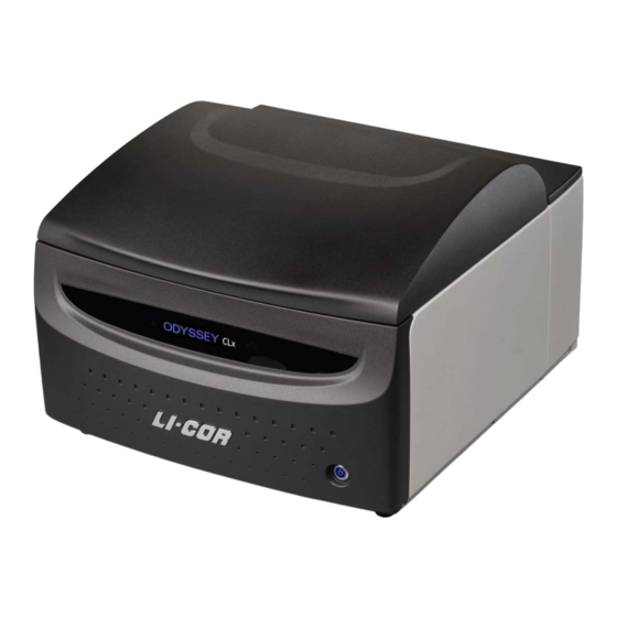
External Panels and Controls Front Panel and Scanning Surface Figure 2-1. Front panel features and power button on the Odyssey CLx. Power On/Off Button: Briefly pressing this button turns the instrument on and off, when the instrument is not connected to the Image Studio™ Software. If the instrument is connected, pressing the button results in the red error light blinking along with a warning sound to alert the user that the instrument is connected to the software. -
Page 16: Rear Panel
Chapter 2: System Overview Figure 2-2. Location of the green image acquisition light and red error light. Red Error Indicator: The error indicator light illuminates when a particular process could not be completed. Rear Panel Power switch CDRH Power regulation receptacle compliance label Manufacturer... -
Page 17: Scanning Surface
Odyssey CLx. To disconnect the power before servicing or moving the instrument, shut down the Odyssey CLx by pressing the power button on the front panel. Then remove the power cord from the power receptacle as described in Electrical Considerations on page 5. -
Page 18: Computer Connections And Networking
The Odyssey® CLx Imager has two modes for dynamic range, Automatic and Manual. In Automatic mode the Odyssey CLx acquires images with virtually no saturated pixels on the first attempt with no user adjustments. More than six logs (22 bits) of dynamic range are available for each image. In Manual mode the intensity of each channel can be manually adjusted across a 12 bit dynamic range. -
Page 19: Image Studio™ Software Overview
Odyssey® CLx Imager Image Studio™ Software Overview Learning the Software Each part of the user interface (button, etc.) has an extensive tool tip associated with it that can be invoked by hovering the mouse over the feature on the user interface. A more comprehensive review of acquiring images as well as analysis functions can be found in the Image Studio Software Help system. - Page 20 Page 12...
-
Page 21: Chapter 3: Operation
It is very important that the glass and silicone mat be free of smudges, dust, and dye before placing membranes or gels onto the Odyssey CLx. Contaminated surfaces in contact with the membrane surface may cause blotches and streaks that cannot be removed with further washing. -
Page 22: Using Gels
Some general considerations for microplate selection are provided here. Plate dimensions must be such that the distance from the Odyssey CLx scanning surface to the target detection area of the plate is 4.0 mm or less. -
Page 23: Using The Mousepod Accessory
Before plate scanning, clean the bottom plate surface with a moist, lint-free paper to remove any obstructions. Additionally, the Odyssey CLx scanning surface should be thoroughly cleaned using the procedures described earlier in this chapter. Protect plates from light before imaging to ensure highest sensitivity. When storing plates after imaging, protect plates from light at room temperature. -
Page 24: Positioning Membranes And Gels
® ® The optional Odyssey MousePOD Accessory fits over the Odyssey CLx scanning surface for in vivo imaging of up to three mice or one rat in a temperature-controlled enclosure. Read more about the MousePOD Accessory at licor.com/support. Positioning Membranes and Gels... -
Page 25: Positioning Microplates
Acquire ribbon scanning bed graphic. Obtaining Technical Support To resolve a problem with your Odyssey CLx, start by contacting LI-COR Technical Support at 800- 645-4260 (U.S. only), or emailing biohelp@licor.com. Outside of the U.S., contact your local sales office or distributor. Be prepared to give the serial number of your instrument, which can be found on the manufacturer label on the rear panel of the instrument (Figure 1-1). - Page 26 Chapter 3: Operation 1) Click the Image Studio Application Button, point to Logs, and then click Export. The Zip Application Log Files dialog will open. 2) In the Zip Application Log Files dialog, keep All log files selected (unless you need to save a smaller file due to email restrictions), and choose where to save the file.
-
Page 27: Chapter 4: Appendix
Network Connection: Cat. 5e RJ45, 10BASE-T/100BASE-TX/1000BASE-T. Use only the supplied cable. Embedded Firmware Source Code The embedded firmware running on the Odyssey CLx Imager (model number 9140) utilizes open source software. To obtain source code or related information, contact LI-COR Support at http://www.licor.com/biotechsupport. - Page 28 Page 20...
Need help?
Do you have a question about the Odyssey CLx and is the answer not in the manual?
Questions and answers