
Related Manuals for Doran Scales 4300 Series


Summary of Contents for Doran Scales 4300 Series
- Page 1 4300 Series Digital Weight Indicator Technical Manual MAN334 – Rev 1 Doran Scales, Inc. www.doranscales.com...
-
Page 2: Table Of Contents
Table of Contents Introduction .......................... 1 Unpacking Your Scale ........................1 4300 Indicator Specifications ......................2 Scale Annunciators.........................3 Power Up............................4 Basic Weighing Operation ......................4 ZERO .............................4 UNITS ............................4 PRINT ............................4 OVER .............................5 UNDER ............................5 Battery Operation ......................... 6 Power Off ............................6 Low Battery Indication ........................6 Recharging Battery.........................6 Three Band Checkweighing .................... - Page 3 Legal for Trade Restrictions ......................19 Audit Counters ..........................19 Software Part Number and Revision Level ..................19 Capacity and Calibration - 1 CAL 1 CAL ....................20 1 CAL 1 CAL General Settings - 2 Cnfg 2 Cnfg 2 Cnfg 2 Cnfg ......................
-
Page 4: Introduction
Introduction Thank you for purchasing a Doran Scales product. Please read this manual to ensure obtaining all the benefits that the 4300 can provide. If any questions arise, please contact the Doran Scales Technical Support Department at 1-800-262-6844. Unpacking Your Scale Before unpacking your Doran scale, please read the instructions in this section. -
Page 5: 4300 Indicator Specifications
4300 Indicator Specifications NTEP Certificate Class III – 10,000d; Cert. #97-038A1 CWM Certificate Class III – 10,000d; Cert. #AM-5201 Enclosure 304 Stainless Steel Product Dimensions 10” W x 6.75” H x 3.5” D Environmental Protection IP69K Legal for Trade 14 F to 104F (-10 C to +40 C) Temperature Range Resolution Range 200d to 50,000d... -
Page 6: Scale Annunciators
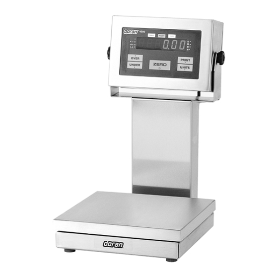
Fig. 1: Model 4300 Front Panel Layout The operational controls for the Model 4300 consist of the ZERO, PRINT, UNITS, OVER and UNDER buttons. A six digit LED display is used to display weight and operator messages during scale operation. Three lights, above the LED display indicate checkweighing status. -
Page 7: Power Up
Under illuminates to indicate weight is below the Under target and above the Low target or flashes if below the Low target. Accept illuminates to indicate weight is at or above the Under target and at or below the Over target. Over illuminates to indicate weight is above the Over target and below the High target or flashes if above the High target. -
Page 8: Over
OVER OVER allows entry of the upper checkweighing limits. It is also used to increment a checkweighing value that is being modified. UNDER UNDER allows entry of the lower checkweighing limits. It is also used to decrement a checkweighing value that is being modified. -
Page 9: Battery Operation
Battery Operation The 4300 can be optionally configured with a self-contained Rechargeable Sealed Lead-Acid battery and charging circuit, both internal. The scale is designed to run continuously for up to 60 hours with a single 350 ohm load cell. To maximize battery life, leave the auto-off timer enabled which will automatically power down the scale after a period of non-use. -
Page 10: Three Band Checkweighing
Three Band Checkweighing Three band checkweighing classifies weighments into over, accept and under. The 4300 defaults to three band checkweighing. Note that lb:oz is not supported for checkweighing limits. Three Band Checkweighing 1. Remove all items from the scale platform 2. -
Page 11: Five Band Checkweighing
Five Band Checkweighing Five band checkweighing classifies weighments into high, over, accept, under and low. See three band checkweighing to set over and under checkweigh limits. The C.o. parameter must be set for five band checkweighing to enable this capability. Note that lb:oz is not supported for checkweighing limits. -
Page 12: Weight Reference Entry Of High And Low Limits
Weight Reference Entry of High and Low Limits 1. Press ZERO 2. Place an item of the desired weight on the scale platform 3. Press and hold the OVER or UNDER until the display reads High or louu respectively 4. The display will briefly read over or under followed by the weight on the platform and checkweigh status annunciators will flash 5. -
Page 13: Zero Band Checkweighing
Zero Band Checkweighing Basic checkweighing - simply set the desired weight on the platform, press zero and checkweigh based upon the standard tolerances in the O.U. parameter. Zero Band Checkweighing 1. Remove all items from the scale platform 2. Place the target weight on the scale platform 3. -
Page 14: Installation Guide
Installation Guide Fig. 2: Motherboard Layout Removing and Replacing the Rear Panel Before you remove the rear panel, remove AC power. Power down the scale if the optional battery power is present. Removing the rear panel requires a 5/16” nut driver. To replace the rear panel and achieve a tight seal, each screw requires a rubber bonded washer and the gasket needs to be in place. -
Page 15: Load Cell Connection
Load Cell Connection Load cell connections are made through terminal block TB1. The power cord connects to terminal block TB5 adjacent to the transformer. Fig. 3: Load Cell and Power (lower left of board) 4 wire load cell 6 wire load cell J1 Jumper J2 Jumper Load Cell Input (TB1) -
Page 16: Power Connection And Fuse
Power Connection and Fuse Power input is located at terminal block TB5, next to the fuse and black transformer. Neutral Ground Line (Hot) Make sure power is off before replacing the fuse. The scale's fuse (F1) is located next to the power terminal (J1). The scale has a filtered power supply to reduce the effects of normal line noise, but it cannot limit severe fluctuations. - Page 17 TB3 RS232 and Remote Switch Connections Description Wire Color Code RS232 Port 1 Receive White RS232 Port 1 Transmit Common Ground Black Remote Switch 1 Input White Remote Switch 2 Input White RS232 Port 2 Receive White RS232 Port 2 Transmit Remote Switch Common Black 4.7Vdc...
-
Page 18: Calibration Guide
Calibration Guide Entering Calibration and Parameter Setup Mode Front Panel Access 1. Press and hold ZERO and UNITS simultaneously until the audit counters are displayed. 2. Ent Cd is displayed 3. Press ZERO 5 times, so that 5 is displayed, 4. -
Page 19: Set Scale Count By
Set Scale Count By After the capacity has been entered, count by (resolution) will automatically be set for a legal for trade 5000 division level. 1. After calibration, press UNITS. 2. The display will alternate between Cnt by and the current count by 3. -
Page 20: Scale Calibration Error Troubleshooting
Scale Calibration Error Troubleshooting The allowable load cell signal input range is 0.30 mV/V to 5.0 mV/V. 1. Calculate scale divisions by dividing the scale capacity by the count by. Example: For a 50 x 0.01 lb scale, divide 50 by 0.01 for a result of 5000d 2. -
Page 21: Scale Parameter Setup
Scale Parameter Setup Entering Calibration and Parameter Setup Mode Front Panel Access 1. Press and hold ZERO and UNITS simultaneously until the audit counters are displayed. 2. Ent Cd is displayed 3. Press ZERO 5 times, so that 5 is displayed, 4. -
Page 22: Parameter Groups
Parameter Groups The scale parameters are divided up into eight parameter groups. Each group contains related parameters. Below is a brief list describing each parameter group. 1 CAL Capacity and Calibration 2 CnFg General Settings 3 SEr1 Serial port #1 4 SEr2 Serial port #2 5 Eth... -
Page 23: Capacity And Calibration - 1 Cal 1 Cal
Capacity and Calibration - 1 CAL 1 CAL 1 CAL 1 CAL Capacity Adjustment Menu CAP Aj CAP Aj CAP Aj CAP Aj Allows the selection of scale capacity 1 lb / kg to 999,000 lb / kg 1 − 999000 Press ZERO to change flashing digit Press PRINT to select next digit Count By Setup Menu (Resolution) - Page 24 Automatic Zero Tracking Range Small weight within the specified number of divisions are automatically zeroed Zero tracking is off, no automatic zeroing Zero tracking to within 0.5 division Zero tracking to within 1.0 division Zero tracking to within 3.0 divisions Zero tracking to within 5.0 divisions Motion aperture * Determines the number of divisions that...
-
Page 25: General Settings - 2 Cnfg 2 Cnfg
Operating mode Standard operation NTEP legal-for-trade. Restricts parameters to keep them within NTEP limits. Same as 44 but disables the front panel access. Peak and hold. The highest weight, above the threshold, is locked on the display. The display resets once the weight falls below the threshold value. - Page 26 Start Up Units Select Mode UnitS UnitS UnitS UnitS Configures selection of startup units The unit annunciator, to the right of the display, indicates the active unit on power up. Press ZERO to change the selection. Push Button Enable and Disable P.b.
- Page 27 Automatic off Timer Selects the amount of time that the scale will remain on while not in use Unit will remain on, On timer is off 30 second On timer 1 1 1 1 1 minute On timer 1.5 minutes On timer 2 minutes On timer 3 minutes On timer 5 minutes On timer...
-
Page 28: Ser1
Serial Port 1 - 3 3 3 3 SEr1 SEr1 SEr1 SEr1 Data Output Mode d.o. 1 d.o. 1 d.o. 1 d.o. 1 Determines when serial data will be transmitted for serial port #1 Transmit on demand. Transmit when the PRINT t.o.d. -
Page 29: Serial Port 2 - 4 Ser2 4 Ser2
Serial Port 2 - 4 4 4 4 SEr2 SEr2 SEr2 SEr2 Data Output Mode d.o. 2 d.o. 2 d.o. 2 d.o. 2 Determines when serial data will be transmitted for serial port #2 Transmit on demand. Transmit when the PRINT t.o.d. -
Page 30: Ethernet - 5 Eth 5 Eth
Ethernet - 5 5 5 5 Eth Data Output Mode (see Print Modes) d.o. E d.o. E d.o. E d.o. E Determines when data will be transmitted for the Ethernet port Transmit on demand. Transmit when the PRINT button is t.o.d. -
Page 31: Wireless Ethernet - 6 Uufi 6 Uufi
Port Port Port Port TCP Port Number xxxxx Indicates the listening TCP port number of the scale. Nnac Nnac Nnac Nnac Ethernet MAC Address The unique Ethernet MAC address. Cannot be xxxxxx.xxxx changed. Wireless Ethernet - 6 6 6 6 uufi uufi uufi uufi... -
Page 32: Bluetooth - 7 Bt 7 Bt
Bluetooth - 7 7 7 7 bt Data Output Mode (see Print Modes) d.o. d.o. bt d.o. d.o. Determines when data will be transmitted for the Bluetooth port Transmit on demand. Transmit when the PRINT button is t.o.d. pressed. Auto Print 1. Transmit once only when scale becomes A.P.1 stable. -
Page 33: Usb 8 Usb
USB - 8 8 8 8 USb Data Output Mode (see Print Modes) d.o. d.o. Usb d.o. d.o. Determines when data will be transmitted for the USB port Transmit on demand. Transmit when the PRINT button is t.o.d. pressed. Auto Print 1. Transmit once only when scale becomes A.P.1 stable. -
Page 34: Checkweighing - 9 Chuu 9 Chuu
Checkweighing - 9 9 9 9 ch chuu C.o..Checkweigh Status Operation Check weighing feature not active Three band checkweighing 3 3 3 3 A A A A Checkweigh status continuously active. Three band checkweighing Only active while weight is stable and inactive while the scale is in motion. - Page 35 C.E. C.E. C.E. C.E. Checkweigh Limit Entry Scroll from recalled value: Use the OVER or UNDER button to recall a limit. Then use the OVER and UNDER buttons to increase or decrease the recalled target value. Reference weight only: Place an item on the platform and press the OVER or UNDER button to enter that weight as a target value.
-
Page 36: Exit - 99 Don 99 Don
Exit - 9 9 9 9 9 9 9 9 don done done done done Exit and save changes Do not exit Save changes and exit... -
Page 37: Data Communications
Data Communications Data Communication Modes The Scale Indicator offers four different communication modes. These modes dictate when data is transmitted. To confirm data has been transmitted, the display will show a "r" to confirm data transmission. tod) Transmit on Demand (tod In this mode, scale data is transmitted whenever PRINT is pressed, a remote switch configured for a PRINT command is pressed, or a print request is received at the serial port. - Page 38 Print String Description Standard Output Format <STX> Start of Text (02h) <p> Weight Polarity <STX><p><xxxx.xx><SP><uu><SP> Negative weight “-”, positive weight <MOT><CR><LF> space (20h) <xxxx.xx> Weight Data fixed field Sample Print String of 6 digits plus decimal. In overload ±--10.05-lb or underload “-------”. Leading zeros are spaces (20h).
- Page 39 Print String Description Label Printer Output Format <p> Weight Polarity Negative weight “-”, positive weight <FR”L1”><LF><?><LF><p><xxxx.xx><LF space (20h) ><uu><LF><"GS"><LF><MOT><LF><p> <xxxx.xx> Weight Data fixed field <xxxx.xx><LF><kg><LF><P1,1><LF> of 6 digits plus decimal. In overload or underload “-------”. Leading zeros Sample Print String are spaces (20h) FR"L1"...
- Page 40 Print String Description Custom Data String 1 (\x\w \u \m\r\l) <STX> Start of Text (02h) <p> Weight Polarity <STX><p><xxxx.xx><SP><uu><SP> Negative weight “-”, positive weight <MOT><CR><LF> space (20h) <xxxx.xx> Weight Data fixed field Sample Print String of 6 digits plus decimal. In overload ±--10.05-lb or underload “-------”.
- Page 41 Print String Description Custom Data String 3 (\xID:\i \w \u \m\r\l) <p> Weight Polarity Negative weight “-”, positive weight <STX><”ID:”> space (20h) <SP><p><xxxx.xx><SP><uu><SP><MO <xxxx.xx> Weight Data fixed field T><CR><LF> of 6 digits plus decimal. In overload or underload “-------”. Leading zeros Sample Print String are spaces (20h) ID:00-±--10.05-lb...
-
Page 42: Custom Data String Configuration
Custom Data String Configuration Programming the custom data string requires the use of a terminal program or Doran Dimension PC program and a communication option such as RS232, Ethernet, USB, WiFi, or Bluetooth. To program the indicator for a custom data string, match the terminal program and the indicator communication parameters. - Page 43 pressing the enter. To program this string for Lb1 location in the scale’s memory, send the following string: EL1\w\u\r\l↵ Once programmed, set the Output Format For parameter to lb1 to activate the print string. Doran Serial Protocol Table 1 Command Scale Response Description W or w...
-
Page 44: 4-20Ma Analog Output Option
4-20mA Analog Output Option Introduction The 4-20mA Analog Output Option is used to provide an analog output that is proportional to the weight on the scale platform. The option board provides an active power loop for the communications. Because of the inherent noise immunity present in a current loop, an isolated 4-20mA analog output is ideal for use in noisy environments. -
Page 45: Wired Ethernet Option
Wired Ethernet Option The Wired Ethernet Option (EXOPT302) connects your Excel Series scale to an Ethernet network. The Ethernet module is installed inside the indicator enclosure. The NEMA4X sealed RJ-45 Ethernet connector is bulkhead mounted to the rear panel of the indicator. -
Page 46: Wireless 802.11B/G Ethernet Option
Wireless 802.11b/g Ethernet Option The Wireless Ethernet Option (EXOPT303) connects your 4300 scale to a wireless network. The Wireless Ethernet Option is fully compliant with the 802.11b/g wireless network standard. Wireless communications are protected by up to a 128-bit security encryption. - Page 47 communications. However, there is no guarantee that interference will not occur in a particular installation. If this equipment does cause harmful interference to radio or television reception, which can be determined by turning the equipment off and on, the user is encouraged to try to correct the interference by one or more of the following measures: Reorient or relocate the receiving antenna •...
- Page 48 Doran Wireless 802.11b/g Ethernet Option Factory Configuration Data Sheet Please fill out this form to provide the customer’s wireless access point configuration. Filling out this form will enable Doran to configure your Wireless Ethernet Option at our factory. Configuration at Doran will save you time and effort configuring the Wireless Ethernet Option when it arrives at your facility.
-
Page 49: Bluetooth Option
Bluetooth Option Doran Scale’s Bluetooth option is a Class 3, Bluetooth 4.0, configured for SPP. The Bluetooth option does not require any external antenna for communication. Once paired, the Bluetooth module will function as a wireless RS232 serial cable. Each Bluetooth module has an individual 12-digit address i.e. -
Page 50: Bluetooth Pairing Instructions
Bluetooth Pairing Instructions The following example connects the scale to a Toshiba Bluetooth Stack running on a Windows PC. Click New Connection Click Next... - Page 51 The driver will search for the scale Select Dual-SPP and click Next...
- Page 52 Click Next once to pair Right-click Dual-SPP and choose Connect Click Yes to connect...
- Page 53 Right-click Dual-SPP and choose Detail… The COM number will be displayed...
- Page 54 Right-click Dual-SPP and choose Connect...
-
Page 55: Troubleshooting
Troubleshooting If any problem persists, contact Doran Tech Support at 800-262-6844. Problem What to Do or Check Weight reading will not Examine the weighing platform for any interferences. Be repeat or does not return to sure that nothing is inside the platform, under the load cell zero when weight is or the weigh bridge structure removed... -
Page 56: Error Messages
Error Messages Message What to Do or Check The scale is in overload. The load on the scale exceeds the ovr Ld capacity by more than 103%. Remove excess weight from Scale overload scale. The scale is in underload. The load on the scale is less udr Ld than the minimum scale capacity by more than -20%. -
Page 57: Default To Factory Settings
Default to Factory Settings To return the setup parameters to factory default, follow these steps. WARNING: Defaulting the scale will require recalibration. 1. Enter Calibration Front Panel Access 1. Press and hold ZERO and UNITS simultaneously until the audit counters are displayed. 2. - Page 58 Doran Scales, Inc. 1315 Paramount Pkwy Batavia, IL 60510 www.doranscales.com 800-262-6844...
Need help?
Do you have a question about the 4300 Series and is the answer not in the manual?
Questions and answers