
Related Manuals for Gree GKHD(12)ABND3A2AI


Summary of Contents for Gree GKHD(12)ABND3A2AI
- Page 1 Service Manual MODEL:GKHD(12)ABND3A2AI GKHD(18)ABND3A2AI GREE ELECTRIC APPLIANCES,INC.OF ZHUHAI...
-
Page 2: Summary And Features
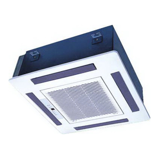
Summary and features Summary and features Model GKHD(12)ABND3A2AI GKHD(18)ABND3A2AI Remote control window Y512... - Page 3 Table Contents ..........1 Summary and features ............Part1 1.Safety Precautions ............Part2 2.SPECIFICATIONS 2.1 Unit Specifications 2.2 Noise criteria curve tables for both models ............Part3 3. Construction Views ............Part4 4. Schematic Diagram 4.1Electrical wiring 4 .2Printed Circuit Board ............
-
Page 4: Safety Precaution
Safety Precautions 1.Safety Precaution Important! or rubbish. The unit should be installed according to the instructions This air conditioning system meets strict safety and in order to minimize the risk of damage from earthquakes, operating standards. As the installer or service person, typhoons or strong winds. -
Page 5: Unit Specifications
Specifications 2.SPECIFICATIONS 2.1 Unit Specifications Models GKHD(12)ABND3A2AI GKHD(18)ABND3A2AI GKHD(12)ABND3A2AI GKHD(18)ABND3A2AI Model (CE012N03600) (CE012N0370) r/min Speed r/min r/min Fan Motor Output Capacitor μF Input Power of Heater Type-Piece centrifugal fan–1 centrifugal fan–1 Diameter-Length φ281X148 Aluminum fin-copper tube Aluminum fin-copper tube Pipe Diameter Φ9.52... -
Page 6: Noise Criteria Curve Tables For Both Models
Specifications 2.2 Noise criteria curve tables for both models Indoor side noise when blowing Middle High Indoor fan motor rotating speed... -
Page 7: Construction Views
Constrction views 3. Construction Views Indoor Unit... -
Page 8: Schematic Diagram
Schematic Diagram 4. Schematic Diagram 4.1Electrical wiring... -
Page 9: Printed Circuit Board
Schematic Diagram 4.2 Printed Circuit Board TOP VIEW input terminal of live line on input terminal 1 control board protective tube piezoresistor relay of transformer input terminal of transformer fan control terminal power zero line terminal terminal 1 used for connecting display board for floor standing water pump control terminal unit... - Page 10 Schematic Diagram BOTTOM VIEW...
-
Page 11: Function And Control
Function and Control 5. Function and Control 5.1 Remote Control Operations Name and Function-Remote control. Note: Be sure that there are no obstructions. Don’t drop or throw the remote controller. Don’t place the remote controller directly in the sunlight. SWING button When it is pressed, the louvers FAN button start to rotate automatically and... - Page 12 Function and Control Name and Function-Remote control. (R emove the cover ) Note: This type of remote controller is a kind of new current one. Some buttons of it that are not available to this air conditioner will not be introduced below. Liquid crystal displayer.
-
Page 13: Cool Mode Operation Procedure
Function and Control COOL mode operation procedure According to difference between room temp. and set temp., microcomputer can control cooling on or not. If room temp. is higher than set temp., compressor runs at COOL mode. If room temp. is lower than set temp., compressor stops and only indoor fan motor runs. Set T EMP. -
Page 14: Heat Mode Operation Procedure
Function and Control HEAT mode operation procedure If room temp. is lower than set temp., compressor runs at HE AT mode. If room temp. is higher than set temp., compressor and outdoor fan motor stop, only indoor fan motor runs. Set T EMP. -
Page 15: Dry Mode Operation Procedure
Function and Control DRY mode operation procedure If room temp. is lower than set temp., compressor ,outdoor fan motors stop,indoor fan motors run at low speed. I f room temp. is between 2 of set temp., Air conditioner is drying.I f room temp. - Page 16 Function and Control AUTO mode operation procedure At AUTO mode operation, standard TEMP. is 25 for COOL mode and 20 for HEAT mode. 1.Plug in,Press ON/OFF button, then air conditioner is turned on. 2.According to room temp.,mcro computer can automatically operation mode,so as for best effect.
-
Page 17: Timer Mode Operation Procedure
Function and Control TIMER mode operation procedure At stopping,press TIMER ON button, set ON T IME in range of 0 to 24 hour to start the unit automatically. At operating,press T IMER OFF button.set OFF T IME in range of 0 to 24 hour to stop the unit automatically. -
Page 18: Sleep Mode Operation Procedure
Function and Control SLEEP mode operation procedure When the unit is cooling or drying, if SLEEP operation is set, TEMP . would increase 1 in 1 hour and 2 in 2 hour s. Indoor fan motor runs at low speed. When the unit is heating , if SLEEP operation is set, TEMP. - Page 19 Function and Control 5.2 Changing batteries and notices How to insert batteries 1. Remove the cover from the back of the remote control. 2. Insert the two batteries ( Two AAA dry - cell batteries ) and press ACL. 3. Re - attach the cover. Note: Don’t confuse the new and worn or different types of...
- Page 20 Function and Control Instruction for wire controller (spare part) NOTE: 1. Never install the wire controller in a place where is water leakage. 2.Avoid bumping, throwing, tossing or frequently opening the wire controller. Composition of wire controller Timer display Sleep display Fan speed display (Auto, High, Middle, MODE button Defrosting display...
-
Page 21: Installation And Transportation
Installation Manual 6. Installation Manual Noise L ocation The air conditioner must be firmly installed and 3 4 Select a place with good ventilation or it may affect liability checks must be done every year. performance or increase noise. Avoid place whthin easy reach of young children. Install the air conditioner on a foundation that can Avoid other heat sources or direct sun light. - Page 22 Installation Manual Accessories Name shape Quantity Notes Drainage hose Clamp Nylon fastener L=200 Washer Paper pad for installaitian Use for Paper pad for Screws ST4.8X13-F installation Heat preservation Sponge for pipe Encase the tie-in Big sealing pad 5X160X300 Sealing pad 5X45X300 Small sealing pad 3X30X150...
-
Page 23: Installation Drawings
Installation Manual Installation drawings Indoor unit Fig.1 Note: Air conditioner must be installed by skilled personnel according to this manual. - Page 24 Installation Manual Location 1.Do not place object near the air oulet so that conditioned air can reach the whole room. 2.Be sure to install the indoor unit firmly and horizontly. 3.Select the place that can support 4 times of the indoor unit’s weight and will not increase noise and vibration. 4.Select a place easy to drain water and connect with the outdoor unit.
- Page 25 Installation Manual Fig.5 Hanging preparations (1) Install special nut A, then special nut B onto the hanging bolt. (Fig.6) (2) Raise the body and mount its hooks onto the hanging bolt between the special nuts. (Fig.6) (3) Turn special nut B to adjust the height of the body. (Fig.6) (4) Leveling a level, or vinyl hose filled with water, fine adjust so that the body is level.
- Page 26 Installation Manual Fig.7 Vinyt hose Installing drain pipe NOTE: Install the drain pipe. Install be drain pipe with downward gradient (1/50 to 1/100) and so there are no rises or traps in the pipe. Use general hard polyvinyl chloride pipe (VP25) [outside diameter 1-1/4” (32mm)] and connect it with adhesive (polyvinyl chloride) so that there is no leakage.
-
Page 27: Connecting The Pipes
Installation Manual Connecting the pipes Besure to use both a spanner and wrench together as shown in the drawing during connecting or disconnecting pipes to/from the unit. The pipe of water-in/out is pipe thread G3/4.The surface of thread should be enlaced by the two or three-circles trap. After the water-in pipe and water-out pipe is connecting tightly,starting the water pump,then checking it’s airproof performance. - Page 28 Installation Manual Electrical wiring How to connect wiring to the terminals A. For solid core wiring (or F-cable) (1) Cut the wire end with a wire cutter or wire-cutting pliers, then stuip the insulation to about 15/16” (25mm) of expose the solid wire.
-
Page 29: Circuit Diagram
Installation Manual Indoor unit side Remove the control box cover and install the connection cord. (Fig. 12 and 13) Fig.12 Control box cover Fig.13 N(1) Note Yellow/Green The temperature of refrigerant circuit will be high, please keep the Blue Black Brown interconnection cable away from the copper tube. - Page 30 Installation Manual Wireless unit connection wire wiring (1). Connect the connector in accorbance part A detail view. (2). Then clamp the lead wire with clamp so that it does not touch the rotating parts. Fig.15 Part A detail view Fig.16 Display PCB wire Wire(Louver) hamess...
- Page 31 Installation Manual (2) Close the intake grille,then slide the tow grille stoppers outward. Grille stopper Fig.18 2.Removing the intake grille (1) Slide the two grille stoppers inward,and then open the intake grill. Fig.19 Grille stopper (2) Remove the geille hook screws, and then open the intake grille. Fig.20 Grille hook (3) Open the intake grille so that it is at an angle of 20°...
-
Page 32: Connection Of Refrigerant Pipe
Installation Manual Caution: (1)The louver angle cannot be changed if the power is non't put throught, (It moved by hand,it may be damaged.) (2) The grille assembly is directional relative to the air conditioner body. (3) Install so that there is no gap between the grille assembly and the air conditioner body. Connection of refrigerant pipe Besure to use both a spanner and torque wrench together as shown in the drawing,connecting or disconnecting pipes to/from the unit. -
Page 33: Exploded Views And Parts List
Exploded Views and Parts list 7. Exploded Views and Parts List 7.1 Exploded View GKHD(18)ABND3A2AI GKHD(12)ABND3A2AI... -
Page 34: Parts List
Exploded Views and Parts list 7.2 Parts List Part Code Description GKHD(12)ABND3A2AI GKHD(18)ABNK3A2AI (CE012N0360) (CE012N0370) Remote Controller 305125063 305125063 Water Tray Assy 20182704 20182704 Water Tray Flannelette 12312702 12312702 Water Tray Foam 12312703 12312703 Sponge 76712709 76712709 Centrifugal fan 10312702... - Page 35 Exploded Views and Parts list Evaporator Connection Board 01072713 01072713 Water Level Switch Support 24212705 24212705 Right Baffle Plate 1362702 1362702 Water Level Switch 450127012 450127012 Pump Gasket 1 76712707 76712707 Pump Gasket 2 76712708 76712708 Pump Drainpipe 05232722 05232722 Pump Support Assy 01332708 01332708...
-
Page 36: Troubleshooting
Troubleshooting 8.Troubleshooting 8.1 General Part Notice 1. Preparation before maintenance Step 1: Firstly, confirm the model of the inverter A/C which needs repairing, and then find out model of main parts that can be damaged easily and the material encode, especially the controller of outdoor unit; Step 2: Basing on the malfunction phenomenon reflected by user, judge the parts which needs for replacing initially, and bring those parts with you for maintenance. - Page 37 Troubleshooting Error Code List Display of wire red light Display of yellow light floor ceiling green light Malfunction Name controller for duct wire controller dual 8 (running LED ) (cooling LED) (heating LED) type unit HIgh pressure protection of blink once system blink twice antifreezing...
- Page 38 Troubleshooting 8.3 Troubleshooting When there’s malfunction or protection for A/C, the display screen of indoor unit or LED will display corresponding code and LED on main board of outdoor unit will also have warnings. Please refer to the function parts as before for details. When protection or malfunction has been eliminated, the display will resume normal status.
-
Page 39: Removal Procedure Of Indoor Unit
Removal Procedure 9.Removal Procedure Removal Procedure of Indoor Unit Warning Be sure to wait 10 minutes or more after turning off all power supplies before disassembling work. Procedure Disassemble grille sub-assy Push the clasps of grille to the middle pull upward simultaneously. - Page 40 Removal Procedure 4. Disassemble electric box Twist off the 2 screws used for fixing the electric box cover and the remove the electric box plate. Pull out the wiring cap of motor and temperature sensor, twist off the 2 screws used for fixing the electric box and then remove the electric box.
- Page 41 Removal Procedure Twist off the 2 screws used for fixing the drain pipe of water pump and then you can draw out the drain drain pipe pipe. screw 7. Disassemble the left baffle plate Twist off the 2 screws used for fixing left baffle plate the baffle plate, pull the baffle plate upward and then remove the left...
- Page 42 Removal Procedure 8. Disassemble centrifugal blade Twist off the nuts used for fixing the centrifugal blade, pull the centrifugal blade upward and then remove it. centrifugal blade 9. Disassemble evaporator connecting plate of evaporator Twist off the screws used for fixing the connecting plate of evaporator and the mounting rack of evaporator, take the connecting board and...
-
Page 43: Care And Cleaning
Care and Cleaning 10. Care and Cleaning Please pull out the power plug after you used the air conditioner. Warning Pull out the power plug before cleaning Do not splash water directly to the unit How to clean the air filter 1.Open the suction grille Use screwdriver screws the two screws. - Page 44 Care and Cleaning 4.Fix the air filters Replace the air filter into its holder. Make sure that the air filter makes contact with the filter stopper when it is replaced into its holder. Shut the suction grille. Refer to step 1. How to clean the suction grille 1.Open the suection grille.
- Page 45 Care and Cleaning Before starting the air conditioner for the first time in the season 1.Check to make sure no objects obstructing the intake and outlets parts on both the indoor and outdoor units. 2.Check to make sure ground wire is connected and that it is not damaged.
- Page 46 GREE ELECTRIC APPLIANCES,INC.OF ZHUHAI Add:Jinji west Rd.Qianshan Zhuhai Guangdong China 86-756-8522219 Tel: (After sale Service Dept) :519070 Post code...
Need help?
Do you have a question about the GKHD(12)ABND3A2AI and is the answer not in the manual?
Questions and answers