Table of Contents
Advertisement
Advertisement
Chapters
Table of Contents

Related Manuals for Gree GUHN09NK3AO


Summary of Contents for Gree GUHN09NK3AO
- Page 1 U-MATCH AIR CONDITIONERS SERVICE MANUAL T1/R410A/50Hz...
-
Page 2: Table Of Contents
CONTENTS PRODUCT ..................... 2 1 MODELS LIST ......................2 1.1 Outdoor Unit ..........................2 1.2 Indoor Unit.............................3 2 NOMENCLATURE ..................... 6 2.1 Outdoor unit ..........................6 2.2 Indoor unit .............................6 3 FUNCTION ........................ 7 4 PRODUCT DATA ....................... 8 4.1 Product Data at Rated Condition ....................8 4.2 Operation Range.........................25 4.3 Electrical Data ..........................25 5 PIPING DIAGRAM .................... - Page 3 3.2 Caution in Connecting Pipes ......................74 ....................75 4 ELECTRIC WIRING WORK ..................75 4.1 Wiring Principle ..........................75 4.2 Electric Wiring Design ........................77 ..............80 MAINTENANCE .................... 84 1 TROUBLE TABLE ...................... 84 2 FLOW CHART OF TROUBLESHOOTING ..............86 3 WIRING DIADRAM ....................
- Page 4 U-MATCH Air Conditioners Service Manual PRODUCT...
-
Page 5: Product
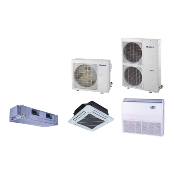
U-MATCH Air Conditioners Service Manual PRODUCT 1 MODELS LIST 1.1 Outdoor Unit Power Model Code Ref. Appearance Supply CF021W0012 GUHN09NK3AO R410a 220-240~,1,50 CF021W0013 CF021W0022 GUHN12NK3AO R410a 220-240~,1,50 CF021W0023 CF021W0052 GUHN18NK3AO R410a 220-240~,1,50 CF021W0053 CF021W0092 GUHN24NK3AO R410a 220-240 ~,1,50 CF021W0093 CF021W0831... -
Page 6: Indoor Unit
U-MATCH Air Conditioners Service Manual 1.2 Indoor Unit 1.2.1 Duct Type Nominal Capacity Power Type Model Code Cooling/Heating Ref. Appearance Supply (Btu/h) GFH09K3BI CF022N0011 8870/9720 GFH12K3BI CF022N0031 11940/12280 GFH18K3BI CF022N0051 17060/19450 GFH24K3BI CF022N0081 23880/27300 GFH30K3B1I CF022N0470 28320/31050 GFH36K3BI CF022N0021 33440/37530 220-240~ R410a 50Hz... - Page 7 U-MATCH Air Conditioners Service Manual 1.2.2 Floor- Ceiling Type Nominal Capacity Power Appearance Type Model Code Ref. Cooling/Heating Supply (Btu/h) GTH09K3BI ED010N0090 8870/9720 GTH12K3BI ED010N0120 11940/12280 GTH18K3BI ED010N0130 17060/19450 GTH24K3BI ED010N0150 23880/27300 GTH30K3B1I ED020N0400 30030/33440 220-240~ R410a GTH36K3BI ED010N0100 34120/37530 50Hz GTH42K3BI ED010N0110...
- Page 8 U-MATCH Air Conditioners Service Manual 1.2.3 Cassette Type Nominal Capacity Power Type Model Code Ref. Appearance Cooling/Heating Supply (Btu/h) GKH12K3BI ET020N0060 11940/12280 GKH18K3BI ET020N0030 17060/18430 GKH24K3BI ET020N0050 23200/25600 GKH30K3B1I ET020N0120 28320/30020 GKH36K3BI ET020N0010 34120/37530 GKH42K3BI ET020N0020 40940/47770 220-240~ R410a 1Ph 50Hz GKH48K3B1I ET010N0560 45040/49470...
-
Page 9: Nomenclature
U-MATCH Air Conditioners Service Manual 2 NOMENCLATURE 2.1 Outdoor unit Description Options Gree Electric Appliances Inc Capital Letter :G U=Match Outdoor Unit F=Duct Type Unit Type K=Cassette Type T= Ceiling Type C=Cool Only Product Type H=Heat Pump without Aux Electric Heaters... -
Page 10: Function
U-MATCH Air Conditioners Service Manual 3 FUNCTION Function Description when unit restart after power off, it will run on former status, Memory function the mode and parameter are kept the same wireless controller and remote controller can be opted, and the Remote control function maximum control distance of remote controller is 10m. -
Page 11: Product Data
4 PRODUCT DATA 4.1 Product Data at Rated Condition 4.1.1 Duct Type Indoor unit GFH09K3BI GFH12K3BI GFH18K3BI Product Code CF022N0011 CF022N0031 CF022N0051 Model Outdoor unit GUHN09NK3AO GUHN12NK3AO GUHN18NK3AO CF021W0012 CF021W0022 CF021W0052 Product Code CF021W0013 CF021W0023 CF021W0053 Cooling Btu/h 8870 11940... - Page 12 U-MATCH Air Conditioners Service Manual Indoor unit GFH24K3BI Product Code CF022N0081 Model Outdoor unit GUHN24NK3AO CF021W0092 Product Code CF021W0093 Cooling Btu/h 23880 Nominal Capacity Heating Btu/h 27300 Cooling 2.66 Power Input Heating 2.51 EER/COP 2.63/3.19 Indoor Unit GFH24K3BI Power Supply 220-240V~/1 Ph/50HZ Heat Exchange Cross Fin Coil...
- Page 13 U-MATCH Air Conditioners Service Manual Indoor unit GFH30K3B1I GFH36K3BI GFH36K3BI Product Code CF022N0470 CF022N0021 CF022N0021 Model Outdoor unit GUHN30NK3A1O GUHN36NK3AO GUHN36NM3AO CF021W0831 CF021W0062 CF021W0032 Product Code CF021W0830 CF021W0063 CF021W0033 Cooling Btu/h 28320 33440 33440 Nominal Capacity 9.10 Heating Btu/h 31050 37530 37530 Cooling...
- Page 14 U-MATCH Air Conditioners Service Manual Indoor unit GFH42K3BI GFH48K3B1I GFH60K3BI Product Code CF022N0041 CF022N0460 CF022N0071 Model Outdoor unit GUHN42NM3AO GUHN48NM3A1O GUHN60NM3AO CF021W0042 CF021W0820 CF021W0082 Product Code CF021W0043 CF021W0821 CF021W0083 13.2 Cooling Btu/h 40940 45040 54600 Nominal Capacity 14.5 18.5 Heating Btu/h 47770 49470...
- Page 15 U-MATCH Air Conditioners Service Manual Indoor unit GFH60K3B2I Product Code CF022N0450 Model Outdoor unit GUHN60NM3A2O Product Code CF021W0810 15.5 Cooling Btu/h 52800 Nominal Capacity 18.5 Heating Btu/h 63120 Cooling Power Input Heating EER/COP 2.50 /3.49 Indoor Unit GFH60K3B2I Power Supply 220-240V~/1 Ph/50HZ Heat Exchange Cross Fin Coil...
- Page 16 U-MATCH Air Conditioners Service Manual Note: a. Nominal capacities are based on the follow conditions. Indoor Outdoor DB:27 C(80.6 DB:35 C(95 Cooling WB:19 C(66.2 WB:24 C(75.2 DB:20 C(68 DB:7 C(44.6 Heating WB:-- C(-- WB:6 C(42.8 Piping Length b. The air volume is measured at the relevant standard external static pressure. c.
- Page 17 U-MATCH Air Conditioners Service Manual 4.1.2 Ceiling Type Indoor unit GTH09K3BI GTH12K3BI GTH18K3BI Product Code ED010N0090 ED010N0120 ED010N0130 Models Outdoor unit GUHN09NK3AO GUHN12NK3AO GUHN18NK3AO CF021W0012 CF021W0022 CF021W0052 Product Code CF021W0013 CF021W0023 CF021W0053 Cooling Btu/h 8870 11940 17060 Nominal Capacity 2.85...
- Page 18 U-MATCH Air Conditioners Service Manual Indoor unit GTH24K3BI Product Code ED010N0150 Models Outdoor unit GUHN24NK3AO CF021W0092 Product Code CF021W0093 Cooling Btu/h 23880 Nominal Capacity Heating Btu/h 27300 Cooling 2.61 Power Input Heating 2.59 EER/ COP 2.68/3.09 Indoor Unit GTH24K3BI Power Supply 220-240V~/1 Ph/50HZ Heat Exchange Cross Fin Coil...
- Page 19 U-MATCH Air Conditioners Service Manual Indoor unit GTH30K3B1I GTH36K3BI GTH36K3BI Product Code ED020N0400 ED010N0100 ED010N0100 Models Outdoor unit GUHN30NK3A1O GUHN36NK3AO GUHN36NM3AO CF021W0830 CF021W0062 CF021W0032 Product Code CF021W0831 CF021W0063 CF021W0033 Cooling Btu/h 30030 34120 33430 Nominal Capacity 10.78 Heating Btu/h 33440 37530 36780 Cooling...
- Page 20 U-MATCH Air Conditioners Service Manual Indoor unit GTH42K3BI GTH48K3B1I Product Code ED010N0110 ED020N0630 Models Outdoor unit GUHN42NM3AO GUHN48NM3A1O CF021W0042 CF021W0820 Product Code CF021W0043 CF021W0821 13.2 Cooling Btu/h 40940 45040 Nominal Capacity 14.5 Heating Btu/h 47770 49470 Cooling Power Input Heating EER/ COP 2.50/2.98 2.64/3.02...
- Page 21 U-MATCH Air Conditioners Service Manual Indoor unit GTH60K3B2I Product Code ED020N0620 Models Outdoor unit GUHN60NM3A2O Product Code CF021W0810 15.5 Cooling Btu/h 52800 Nominal Capacity 18.5 Heating Btu/h 63120 Cooling Power Input Heating EER/ COP 2.58/3.49 Indoor Unit GTH60K3B2I Power Supply 220-240V~/1Ph/50HZ Heat Exchange Cross Fin Coil...
- Page 22 U-MATCH Air Conditioners Service Manual 4.1.3 Cassette Type Indoor unit GKH12K3BI GKH18K3BI GKH24K3BI Product Code ET020N0060 ET020N0030 ET020N0050 Models Outdoor unit GUHN12NK3AO GUHN18NK3AO GUHN24NK3AO CF021W0022 CF021W0052 CF021W0092 Product Code CF021W0023 CF021W0053 CF021W0093 Cooling Btu/h 11940 17060 23200 Nominal Capacity Heating Btu/h 12280 18430...
- Page 23 U-MATCH Air Conditioners Service Manual Indoor unit GKH36K3BI GKH36K3BI Product Code ET020N0010 ET020N0010 Models Outdoor unit GUHN36NK3AO GUHN36NM3AO CF021W0062 CF021W0032 Product Code CF021W0063 CF021W0033 Cooling Btu/h 34120 34120 Nominal Capacity Heating Btu/h 37530 37530 Cooling Power Input Heating EER/COP 2.78/3.33 2.78/3.55 Indoor Unit GKH36K3BI...
- Page 24 U-MATCH Air Conditioners Service Manual Indoor unit GKH42K3BI Product Code ET020N0020 Models Outdoor unit GUHN42NM3AO CF021W0042 Product Code CF021W0043 Cooling Btu/h 40940 Nominal Capacity Heating Btu/h 47770 Cooling Power Input Heating EER/COP 2.5/2.8 Indoor Unit GKH42K3BI Power Supply 220-240V~/1 Ph/50HZ Heat Exchange Cross Fin Coil Type...
- Page 25 U-MATCH Air Conditioners Service Manual Indoor unit GKH30K3B1I GKH48K3B1I Product Code ET010N0060 ET010N0560 Models Outdoor unit GUHN30NK3A1O GUHN48NM3A1O CF021W0831 CF021W0820 Product Code CF021W0830 CF021W0821 13.20 Cooling Btu/h 28320 45040 Nominal Capacity 14.50 Heating Btu/h 30020 49470 Cooling Power Input Heating 3.15 EER/COP 2.86/2.79...
- Page 26 U-MATCH Air Conditioners Service Manual Indoor unit GKH42K3B1I GKH48K3B3I Product Code ET010N0780 ET010N0790 Models Outdoor unit GUCN42NM3AO GUCN48NM3AO Product Code CF021W1860 CF021W1870 13.3 Cooling Btu/h 42000 45000 Nominal Capacity Heating Btu/h Cooling Power Input Heating EER/COP 2.73/- 2.77/- Indoor Unit GKH42K3B1I GKH48K3B3I Power Supply...
- Page 27 U-MATCH Air Conditioners Service Manual Indoor unit GKH60K3B2I Model Outdoor unit GUHD60NM3A2O 15.5 Cooling Btu/h 52800 Nominal Capacity 18.0 Heating Btu/h 61410 Cooling Power Input Heating EER/COP 2.58/3.40 Indoor Unit GKH60K3B2I Power Supply 220-240V~ 50Hz Heat Exchange Cross Fin Coil Type Centrifugal fan Drive...
-
Page 28: Operation Range
Cooling (with low Ambient kit) Heating 4.3 Electrical Data Outdoor unit Compressor Fan Motor Fuse/Breaker Min. Power Capacity Supply Cord Model Power Supply Qty. V/Ph/Hz GUHN09NK3AO 4.28 0.27 GUHN12NK3AO 0.27 GUHN18NK3AO 0.27 220-240,1,50 GUHN24NK3AO 11.2 0.61 GUHN30NK3A1O 13.5 GUHN36NK3AO 18.32 GUHN36NM3AO 6.58... - Page 29 U-MATCH Air Conditioners Service Manual Indoor unit Fuse/Breaker Min. Power Power Supply Fan Motor FLA Capacity Supply Cord Model V/Ph/Hz GFH09K3BI 220-240,1,50 0.18 GFH12K3BI 220-240,1,50 0.18 GFH18K3BI 220-240,1,50 0.63 GFH24K3BI 220-240,1,50 1.35 GFH36K3BI 220-240,1,50 GFH42K3BI 220-240,1,50 GFH60K3BI 220-240,1,50 GFH30K3B1I 220-240,1,50 GFH48K3B1I 220-240,1,50 GFH60K3B2I...
-
Page 30: Piping Diagram
U-MATCH Air Conditioners Service Manual 5 PIPING DIAGRAM Outdoor Heat Exchange 4-way Valve Compressor Check Valve Capillary Tube Outdoor Vapour Liquid Separator Stop Valve Indoor Capillary Tube Heating Cooling Heat Exchange... - Page 31 U-MATCH Air Conditioners Service Manual CONTROL...
-
Page 32: Control
U-MATCH Air Conditioners Service Manual CONTROL 1 OPERATION FLOWCHART 1.1 Cooling/Dry Operation... -
Page 33: Heating Operation
U-MATCH Air Conditioners Service Manual 1.2 Heating Operation... -
Page 34: Main Logic
U-MATCH Air Conditioners Service Manual 2 MAIN LOGIC 2.1 Cooling Cooling mode Starting up Manual shutdown Compressor Outdoor fan H grade Operation at a set speed Indoor fan 4-way valve Time When T C, the unit begins cooling operation and the compressor and the outdoor fan are amb. -
Page 35: Heating Mode
U-MATCH Air Conditioners Service Manual 2.3 Heating Mode Heating Mode Starting up Manual shutdown Compressor Outdoor fan Operation at Operation in blowing a set speed after heat state Indoor fan Operation under normal conditions Auxiliary heating 4-way valve Time 1S 20S Cold blast prevention When T... -
Page 36: Fan Mode
U-MATCH Air Conditioners Service Manual 2.5 Fan Mode Fan Mode Starting up Manual shutdown Compressor Outdoor fan Operation at H grade a set speed Indoor fan 4-way valve Time The indoor fan runs at a fast speed for 5s and then runs at a set speed. 3 WIRELESS REMOTE CONTROLLER 3.1 Operation View (1) Controller-Duct Type... - Page 37 U-MATCH Air Conditioners Service Manual Name Function description ON/OFF button Press the button to set start or close unit Mode button Press the button to select the mode,cooling , heating , fan or auto mode. Increase/Decrease button Press this button to increase/decrase the setup temp LCD Screen Display the status of remote information Swing button...
-
Page 38: Display View
U-MATCH Air Conditioners Service Manual 3.2 Display View Display Function description :auto fan speed; :low fan speed; Fan Speed :middle fan speed; :high fan speed; :Auto running; :Cool running; :Dry Running; :Fan Running; Run Mode :Heat running (Heat and Cool unit only) Setup temp Temperature value of setting Swing function... - Page 39 U-MATCH Air Conditioners Service Manual (2) Wired Controller-Cassette Type and Ceiling Type MODE SWING TIMER ON/OFF Name Function description Press the button to select the mode, MODE button cooling , heating , fan or auto mode. Increasing button Press this button to increase the setup temp. Decreasing button Press this button to decrase the setup temp.
-
Page 40: Display View
U-MATCH Air Conditioners Service Manual 4.2 Display View MODE SWING TIMER ON/OFF Name Function description Timer value Display time value Timer on/off :display timer on; :display timer off; :auto fan speed; :low fan speed; Fan speed display :middle fan speed; :high fan speed Display set temp value its range is 16~30... -
Page 41: Dimension
U-MATCH Air Conditioners Service Manual 4.3 Dimension Installation dimension Outline dimension 4.4 Installation 1. First select an installation position. According to the size of the communication line of the wire controller, leave a recess or a embedded wire hole to bury the communication line. 2. -
Page 42: Centralized Controller
U-MATCH Air Conditioners Service Manual Fig 8 :Schematic Diagram of Installation Name Wall Surface Bottom Plate of Wire Controller Screw M4X10 Panel of Wire Controller Caution: a. The communication distance between the main board and the wire controller can be as far as 20m (The standard distance is 8m). -
Page 43: Centralized Controller-Week Timer
U-MATCH Air Conditioners Service Manual 5.1.3 Display View Display unit address value in the net. 5.1.4 Dimensions 5.2 Centralized Controller-week timer 5.2.1 Function Centralized Control and Week Timer Functions: The centralized controller and the weekly timer are integrated in the same wire controller. The system has both the centralized control and the week timing functions. - Page 44 U-MATCH Air Conditioners Service Manual 5.2.2 Operation View Name Function description ENTER button when “enter” is pressed the setting is validate. Increasing button Press “ ” and selected the unit or a certain day in one week Decreasing button ” can set week part of time. CANCEL/DELETE short-press “cancel/delete”...
-
Page 45: Field Setting
U-MATCH Air Conditioners Service Manual Name Function description unit’s no. displays Display unit’s numbers Group control displays when group controls, it will display Single control displays when single unit controls, it will display Timer time in week displays Display time in week Timer displays Display time “on”: when set unit on, “on”... -
Page 46: Control Wiring Design
U-MATCH Air Conditioners Service Manual Position Serial No. Position Serial No. Position Serial No. Position Serial No. 0000 0100 1000 1100 0001 0101 1001 1101 0010 0110 1010 1110 0011 0111 1011 1111 As shown in the following diagram: Unit code:2 Unit code:4 0000 0001... -
Page 47: Display View Of The Cassette Type Unit Which With Control Panel
U-MATCH Air Conditioners Service Manual Wired remote controllerW ired remote controller Week timer 16 Units in Max Telephone wire box Telephone wire box Telephone wire box Power supply 220~ Twisted-wire with crystal joint Longest distance 1200m AC-L AC-N Corresponding relation between code switch and sequence of unit (Note:Putting code switch to ON means 0.) 0000 0010... - Page 48 U-MATCH Air Conditioners Service Manual Note: When connecting the unit with new panel to wired remote controller, the control panel should be set as an slave controller; otherwise the unit can not be normally operated. Instructions to the Error Indicating Lamps on the Dash Receiver of the Cassette Type Unit Power and ON/OFF Indicating Lamp: It goes red when the unit is powered on while it goes white when the unit is started.
- Page 49 U-MATCH Air Conditioners Service Manual If there is no any response to the last button press in 20 seconds, then the system will quit this menu and back to the normal “Off” status, without the set parameter saved. (1). Three Grades of Speed for Indoor Fan: under the debugging condition, “L1” is displayed on the “88” display, then, press the “Test”...
- Page 50 U-MATCH Air Conditioners Service Manual INSTALLATION...
-
Page 51: Installation
U-MATCH Air Conditioners Service Manual INSTALLATION 1 INDOOR UNIT INSTALLATION 1.1 Installation of Duct Type 1.1.1 Before Installation When the unit arrives, please check if any damage due to transport is existent. If any hurt is found on the surface or inside, please declare to the transport company or the manufacturer in writing. Upon receipt of the unit, the unit and accessories shall be checked in accordance with the packing list. - Page 52 U-MATCH Air Conditioners Service Manual 4. Install the hanger onto the indoor unit as Figure 1-1-2 and Figure 1-1-3 shows. 5. Install the indoor unit at the ceiling as Figure 1-1-5shows. Screw Hanger Air Intake Air Supply I Enlargement Figure 1-1-5 6.
- Page 53 U-MATCH Air Conditioners Service Manual 1.1.4 Dimension Data ElectricBox GasPipe AirIntake AirIntake DrainagePipe Be Suit for: AirIntake GasPipe DrainagePipe ElectricBox e Suit for: Figure 1-1-7...
- Page 54 U-MATCH Air Conditioners Service Manual Unit:mm Model 1159 1115 1226 1115 1226 List of Accessories for Installation of Indoor Unit Designation and shape Description Operation and installation instructions Heat insulating material for large connector For air pipe connector of indoor unit Heat insulating material for small connector For refrigerant pipe connector of indoor unit Heat insulation material for drain pipe...
- Page 55 U-MATCH Air Conditioners Service Manual 1.1.5 Installation Clearance Data Nut with washer Nut spring washer >250 >250 Indoor Unit Figure 1-1-8 1.1.6 Drain Piping Work 1. Installation of Drainage Pipeline A drainage outlet is located at both the left and right sides of the indoor unit. After selecting one drainage outlet, the other outlet shall be blocked by rubber plug.
- Page 56 U-MATCH Air Conditioners Service Manual Insulating layer of condensate pipe Pipe cover 1.1.7 Installation of air pipes and openings Caution: The air supply pipe, the air intake pipe and the fresh air pipe must be covered with a layer of thermal adhesive tape to carefully seal the joints;...
- Page 57 U-MATCH Air Conditioners Service Manual Installation of circular duct, as shown in Figure 1-1-12 Designation Designation Hanger rod Transition duct Air return duct Air supply duct Canvas duct Air diffuser Return air shutter Connector of air diffuser Air outlet Note: The above two diagrams show how back return air inlets are installed. Lower return air inlets shall be used according to actual installation demands.
- Page 58 U-MATCH Air Conditioners Service Manual Back air intake Down air intake Air intake cover board Figure 1-1-14 their respective position. The air return duct shall be connected to the air return inlet on the indoor unit with rivets, and the other end of the air return duct is connected to an air return window.
-
Page 59: Installation Of Ceiling Type
U-MATCH Air Conditioners Service Manual 1.2 Installation of Ceiling Type 1.2.1 Before Installation When the unit arrives, please check if any damage due to transport is existent. If any hurt is found on the surface or inside, please declare to the transport company or the manufacturer in writing. When the unit arrives, please check if any damage due to transport is existent. - Page 60 U-MATCH Air Conditioners Service Manual Figure 1-2-3 Hanger bracket Figure 1-2-4 In case of hanging: It is possible to install using inward facing hanger bracket by not removing the brackets from the indoor Figure 1-2-5 Figure 1-2-6 1.2.4 Dimension Data Figure 1-2-7...
- Page 61 U-MATCH Air Conditioners Service Manual Unit: mm Model 1354 1491 1634 1.2.5 Installation Clearance Data m ore m ore m ore m ore m ore Figure 1-2-8 1.2.6 Drain Piping Work 1. Installation of Drainage Pipeline A Drainage outlet is located at both the left and right sides of the indoor unit. After selecting one Drainage outlet, the other outlet shall be blocked by rubber plug.
-
Page 62: Installation Of Cassette Type
U-MATCH Air Conditioners Service Manual 2. Testing of Drainage System After the electrical installation is completed, carry out the testing of the drainage system. During the test, check if the water correctly flows through the pipelines. Carefully observe the joints to ensure that there is no leakage. - Page 63 Please contact the local Gree special nominated repair department before installation. Any malfunction caused by the unit that is installed by the department that is not special nominated by Gree would not deal with on time by the inconvenience of the business contact.
- Page 64 U-MATCH Air Conditioners Service Manual Figure 1-3-2 788(Gaps between hoisting screm rods) Figure 1-3-3 The drilling of holes in the ceiling must be done by the professional personnel. Installation stands for main body of the unit Ceiling Cautions:...
- Page 65 U-MATCH Air Conditioners Service Manual 3. Main body of hoisting air conditioner Nut (supplied at scene) Gasket (attachment) Insert Hoisting stand Gasket anchor board (attachment) Tighten(double nuts) Bolt of one of the angle of angle of the drainage slot Center of the ceiling opening Install cardboard Water level Bolt (attachment)
- Page 66 U-MATCH Air Conditioners Service Manual 1.3.4 Dimension Data Figure 1-3-5-1 Unit:mm Item Model Figure 1-3-5-2...
- Page 67 U-MATCH Air Conditioners Service Manual Unit:mm Item Model 1.3.5 Installation Clearance Data Models H(mm) Unit:mm Figure 1-3-6 1.3.6 Drain Piping Work 1. Installation of Drainage Pipeline When connecting the drainage pipe with the unit, do not apply excessive force to the pipeline at the side of Purchase general-purpose hard PVC pipe locally to be used as the drainage pipeline.
- Page 68 U-MATCH Air Conditioners Service Manual 3. Matters of Attention bubble. If drain hose cannot has enough drooping gradient, drain raising pipe should be added. To prevent bent of the drain hose, the distance between hoisting stand should is 1 to 1.5m. (As shown in Figure 1-3-8) 1-1.5m ×(wrong)
- Page 69 U-MATCH Air Conditioners Service Manual Check the smoothness of drain after installation. 1-3-12) Check the drain in the state of refrigerating after installation of the electric circuit. Drain hose est hole cover Drain vent for repair use (plastic stopper is included) (drain the water in waterspout by this outlet vent) Test hole <...
- Page 70 U-MATCH Air Conditioners Service Manual Step 1: Find out the label on the unit, as shown below: Step 2: Tear away this label, and clear the sponge underneath it and inside the center hole to let two screw holes exposed completely.
- Page 71 U-MATCH Air Conditioners Service Manual Screw all 4 hexagon head screws located right beneath the latches in approximately 15mm.(Panel will rise) Adjust the panel by turning it to the arrowed direction in Fig.4 so that the ceiling opening is completely covered.
-
Page 72: Outdoor Unit Installation
U-MATCH Air Conditioners Service Manual 2 OUTDOOR UNIT INSTALLATION 2.1 Before Installation When the unit arrives, please check if any damage due to transport is existent. If any hurt is found on the surface or inside, please declare to the transport company or the manufacturer in writing. Upon receipt of the unit, the unit and accessories shall be checked in accordance with the packing list. -
Page 73: Dimension Data
U-MATCH Air Conditioners Service Manual If pipe is put through wall, a wall pipe must be used. the mounting position. Only professional personnel are allowed for unit installation 2.4 Dimension Data Figure 2-4-1 Unit:mm Model GUHN36NM3AO GUHN42NM3AO GUHN48NM3A1O GUCN42NM3AO GUCN48NM3AO... -
Page 74: Installation Clearance Data
U-MATCH Air Conditioners Service Manual 2.5 Installation Clearance Data >2m Figure 2-5-1 3.1 Refrigeration Piping Work Procedures 1. Connecting pipelines dry, clean and no leakage inside. Clean Air tight Make syre there is no moisture inside the Make sure the refrigerant does not leak Make sure there is no dirt inside the pipe pipes Leak... - Page 75 U-MATCH Air Conditioners Service Manual Pipe diameter 1/4" 3/8" 5/8" 1/2" 3/4" 1-75 Curvature of piping shall not be too small, or otherwise piping may be broken. So installation personnel should use a pipe bender to bend pipes. Upward or longitudinal welding joint method is usually applied to the welding of pipelines. The welding method that mouth of pipe is downward (face-down welding) should be avoided as far as possible, because such method is prone to welding defects and even would cause leakage, as shown in Figure 3-1- Recommended methed...
- Page 76 U-MATCH Air Conditioners Service Manual Tighten the valve caps and use soapy water or a leak detector to check any leakage on indoor unit, outdoor unit and connection parts of pipes. Caution: If conditions are allowed, a vacuum pump shall be used for drawing off air inside the system at a valve. Method for creation of vacuum by using a vacuum pump is as follows: Take out the nut cover of the inlet for refrigerant.
-
Page 77: Caution In Connecting Pipes
U-MATCH Air Conditioners Service Manual cover half of the front circle of tape (Figure 3-1-7). Caution: After the pipes are wrapped by protective materials, never bend the pipes to form very small angle, and otherwise the pipes may crack or break. After the protective work is completed and the pipes are wrapped, use seal material to block the hole in the wall, so as to prevent rain and wind from entering the room. -
Page 78: Electric Wiring Work
U-MATCH Air Conditioners Service Manual Maximum Difference Maximum Length Additional Charge in Height between External Diameter of Connection Outdoor and Indoor of Refrigerant Model Pipe Unit Gas Pipe (g/m) 3/8" 1/4" 1/2" 1/4" 5/8" 3/8" GUHN36NM3AO GUHN42NM3AO 3/4" 1/2" GUHN48NM3A1O GUCN42NM3AO 3/4"... - Page 79 U-MATCH Air Conditioners Service Manual b. Gas pipe; c. Blowing pipe; d. Other places that professional personnel consider them unreliable; 4.1.2 Connection of electric wires with the terminal 1. Caution specially pointed out by our designers: larger than 2.5mm The lines must be installed by professional personnel. An electricity leakage protection switch and an air switch with gap between electrode heads larger than 3 2.
-
Page 80: Electric Wiring Design
U-MATCH Air Conditioners Service Manual 4.1.3 Power Cable Connection 1. Air-conditioning unit with single-phase power supply Remove the front-side panel of the outdoor unit. Pass the cable though rubber ring. Connect the power supply cable to the “L, N” terminals and the grounding screw. 2. - Page 81 U-MATCH Air Conditioners Service Manual Ceiling Type IntdoorUnit OutdoorUnit breaker breaker POWER: POWER: 220-240V ~ 220-240V ~ L N PE L N PE 50 Hz 50 Hz breaker breaker POWER: POWER: 380-415V 3N~ 220-240V ~ 50 Hz L1L2 L3 NP E L N PE 50 Hz...
- Page 82 U-MATCH Air Conditioners Service Manual Cassette Type...
- Page 83 U-MATCH Air Conditioners Service Manual 4.3.1 Outdoor Unit Minimum Sectional Capability of Minimum Sectional Area of Power Power Supply Air Swith Area of Earth Wire Model Supply Wire GUHN36NM3AO GUHN42NM3AO GUHN48NM3A1O GUCN42NM3AO GUCN48NM3AO...
- Page 84 U-MATCH Air Conditioners Service Manual 4.3.2 Indoor Unit Duct Type Minimum Sectional Capability of Minimum Sectional Area of Power Power Supply Air Swith Area of Earth Wire Model Supply Wire Ceiling Type Minimum Sectional Capability of Minimum Sectional Area of Power Supply Power Supply Air Swith Area of Earth Wire...
- Page 85 U-MATCH Air Conditioners Service Manual Cassette Type Capability of Air Minimum Sectional Minimum Sectional Area Power Supply Swith Area of Earth Wire of Power Supply Wire Model...
- Page 86 U-MATCH Air Conditioners Service Manual MAINTENANCE...
-
Page 87: Maintenance
U-MATCH Air Conditioners Service Manual MAINTENANCE 1 TROUBLE TABLE Trouble Origin of Trouble Name Control Description Code Trouble Signal If water full protection continues for 2 hours and fails to Pump Failure Pump restore, it is believed that the water pump is at fault and all loads are shut off and fail to restore automatically. - Page 88 U-MATCH Air Conditioners Service Manual Trouble Origin of Trouble Name Control Description Code Trouble Signal Open-circuit or short-circuit of the indoor environment thermal bulb is detected for continuous 5 seconds, indoor environment temperature will be set compulsively at 24 degree, the system does not take any measure, Failure of Indoor Room Indoor environment and only the indicator is twinkling or fault code F0 is displayed.
-
Page 89: Flow Chart Of Troubleshooting
U-MATCH Air Conditioners Service Manual Cassette Type Indoor Unit’s Error Indicating: Flash times No error every two Error description seconds once the indoor ambient temperature sensor error twice the evaporator temperature sensor error It goes on as per the yellow: Timing three times the condenser temperature senor error indicating lamp... -
Page 90: Service Manual
U-MATCH Air Conditioners Service Manual Malfunction display: E1 Compressor High Pressure Protection High pressure protection Check if the pressure is really high pressure with the Replace the outdoor unit Check if pressure switch is normal measurement of a manometer mainboard Replace pressure switch Check if operation mode of indoor unit is Refer to Instruction... - Page 91 U-MATCH Air Conditioners Service Manual Malfunction display: E3 Compressor Low Pressure Protection Compressor Low Pressure Protection Check if the pressure is really low pressure Refer to the high pressure with the measurement of a manometer protection Charge refrigerant according to the amount Check if refrigerant in the system is specified in the nameplate and calculated insufficient...
- Page 92 U-MATCH Air Conditioners Service Manual Malfunction display: E4 Compressor Exhaust High Temperature Protection Disc harge t emperature protection Replace relevant Measure if c ompressor’s disc harge Measure if t emperature sensor’s disc harge t emperature temperature has reached 130 resistance value is co rrect sensor Syst em pipeline leaks so c omplementation is Replace the outdoor unit...
- Page 93 U-MATCH Air Conditioners Service Manual Malfunction display: E6 Communications Failure...
- Page 94 U-MATCH Air Conditioners Service Manual Malfunction display: E9 Full Water Protection Full Water Protection Check if the voltage of liquid level Replace the main board Check if water overflow switch end is ok of the indoor uint Check the liquid level switch Check if the water drainage pump...
- Page 95 U-MATCH Air Conditioners Service Manual Malfunction display: F1 Failure of Evaporator Temp. Sensor Failure of condenser Temp. sensor Check if the plug of the temperature sensor is correctly Check the direction of the connected with socket on the mainboard plug and socket Remove the sensor to check if the resistance Replace temperature sensor value is ok...
- Page 96 U-MATCH Air Conditioners Service Manual Malfunction display: F4 Failure of Exhaust Temp. Sensor Failure of Exhaust Temp. sensor Check if the plug of the temperature sensor is correctly Check the direction of the connected with socket on the mainboard plug and socket Remove the sensor to check if the resistance Replace temperature sensor value is ok...
-
Page 97: Wiring Diadram
U-MATCH Air Conditioners Service Manual 3 WIRING DIADRAM 3.1 Wiring Diagram-Outdoor Units 1. GUHN09NK3AO WITH FUNCTION OF LOW TEMP. COOLING: WITHOUT FUNCTION OF LOW TEMP. COOLING:... - Page 98 U-MATCH Air Conditioners Service Manual 2. GUHN12NK3AO WITH FUNCTION OF LOW TEMP. COOLING: WITHOUT FUNCTION OF LOW TEMP. COOLING:...
- Page 99 U-MATCH Air Conditioners Service Manual 3. GUHN18NK3AO WITH FUNCTION OF LOW TEMP. COOLING: WITHOUT FUNCTION OF LOW TEMP. COOLING:...
- Page 100 U-MATCH Air Conditioners Service Manual 4. GUHN24NK3AO WITH FUNCTION OF LOW TEMP. COOLING: WITHOUT FUNCTION OF LOW TEMP. COOLING:...
- Page 101 U-MATCH Air Conditioners Service Manual 5. GUHN36NK3AO WITH FUNCTION OF LOW TEMP. COOLING: WITHOUT FUNCTION OF LOW TEMP. COOLING:...
- Page 102 U-MATCH Air Conditioners Service Manual 6. GUHN36NM3AO WITH FUNCTION OF LOW TEMP. COOLING: WITHOUT FUNCTION OF LOW TEMP. COOLING:...
- Page 103 U-MATCH Air Conditioners Service Manual 7. GUHN42NM3AO WITH FUNCTION OF LOW TEMP. COOLING: WITHOUT FUNCTION OF LOW TEMP. COOLING:...
- Page 104 U-MATCH Air Conditioners Service Manual 8. GUHN60NM3AO WITH FUNCTION OF LOW TEMP. COOLING: WITHOUT FUNCTION OF LOW TEMP. COOLING:...
- Page 105 U-MATCH Air Conditioners Service Manual 9. GUHN30NK3A1O; WITH FUNCTION OF LOW TEMP. COOLING: WITHOUT FUNCTION OF LOW TEMP. COOLING:...
- Page 106 U-MATCH Air Conditioners Service Manual 10. GUHN48NM3A1O; WITH FUNCTION OF LOW TEMP. COOLING: WITHOUT FUNCTION OF LOW TEMP. COOLING:...
- Page 107 U-MATCH Air Conditioners Service Manual 11. GUHN60NM3A2O; WITH FUNCTION OF LOW TEMP. COOLING: Outdoor Unit POWER 18 WH Capacitor AP2-AC-L Comp Relay Transformer TR-IN AC-L Converse Protector Terminal Board Transformer TR-OUT Over Current Protector X15(N) Reverse Protector AP2-AC-N X4(HPP) ACContactor X11(4V) X3(LPP) X1(OVC-COMP)
-
Page 108: Wiring Diagram-Indoor Units
U-MATCH Air Conditioners Service Manual 12. GUCN42NM3AO; GUCN48NM3AO 3.2 Wiring Diagram-Indoor units 3.2.1 Duct Type Model:GFH09K3BI; GFH12K3BI; GFH18K3BI; GFH24K3BI; GFH30K3B1I; GFH36K3BI; GFH42K3BI; GFH48K3B1I; GFH60K3BI; GFH60K3B2I;... - Page 109 U-MATCH Air Conditioners Service Manual 3.2.2 Cassettle Type Model:GKH12K3BI; GKH18K3BI; GKH24K3BI; GKH30K3B1I; GKH36K3BI; GKH42K3BI; GKH48K3B1I mode of connection 1 mode of connection 2 Model: GKH42K3B1I, GKH48K3B3I...
- Page 110 U-MATCH Air Conditioners Service Manual Model:GKH60K3B2I; POWER CN27 INDOOR UNIT Receiving Board YEGN YEGN AC-N AC-L U-SWING2 DISP2 DISP1 U-SWING1 YEGN E500 Pipe Temp. Sensor PUMP DC-MOTOR1 PUMP-C Environment Temp. Sensor YEGN EVAPORATOR LIQUID PUMP SWING MOTOR MOTOR 3.2.3 Ceiling Type Model:GTH09K3BI;...
- Page 111 U-MATCH Air Conditioners Service Manual Model: GTH30K3B1I; Model: GTH60K3B2I;...
-
Page 112: Disassembly And Assembly Procedure Of Main Parts
U-MATCH Air Conditioners Service Manual 4 DISASSEMBLY AND ASSEMBLY PROCEDURE OF MAIN PARTS 4.1 Outdoor Unit GUHN09NK3AO~ GUHN36NK3AO Disassembly and Assembly of external casing Remark: Make sure that power supply is cut off before disassembling the external casing. Step Illustration Handling Instruction 1. - Page 113 U-MATCH Air Conditioners Service Manual 6. Assembly of new right (back) panel screwdriver. on the unit; 7. Assembly of new panel screwdriver. (external casing) equipped with front panel outside the external casing. 8. Assembly of new panel unit grating screwdriver. 9.
- Page 114 U-MATCH Air Conditioners Service Manual Disassembly and Assembly of Compressor Remark : Make sure there isn’t any refrigerant in pipe system and the power supply is cut off before removal of the compressor. Step Illustration Handling Instruction Disassemble compressor wire wire with screwdriver.
- Page 115 U-MATCH Air Conditioners Service Manual Disassemble compressor wire 7 . C o r r e c t c o n n e c t i o n o f of disassembly. wires for power supply of compressor with screwdriver. Vacuum pumping injection mouth through process pipe 9.
- Page 116 U-MATCH Air Conditioners Service Manual with gas welding before removal of 4-way valve. 3. Disassembly of 4-way valve installation postition of each pipe before welding away 4-way valve. Disassemble connecting pipes at E,S,D and C orifices 4. Removal of 4-way valve 5.
- Page 117 U-MATCH Air Conditioners Service Manual 7. Examination of System and system leak test passes. Disassembly and Assembly of capillary Remark: Make sure there isn’t any refrigerant in pipe system and the power supply is cut off before removal of the capillary. Step Illustration Handling Instruction...
- Page 118 U-MATCH Air Conditioners Service Manual 3. Assembly of New vapor line using gas welding. liquid separator Illustration 1. Disassembly of outer parts 2. Disassembly of axial flow panel(external casing), screen,etc. according to the discription above in order to disassemble 3. Disassembly of fan motor 4.
- Page 119 U-MATCH Air Conditioners Service Manual support. corresponding position inside the electrical parts box and fasten the connecting plug. 6. Assembly of outer parts Disassembly and Assembly of electrical parts box Remark: Make sure power supply of the unit is cut down before removal of electrical parts box or electrical parts box modules. Step Illustration Handling Instruction...
- Page 120 U-MATCH Air Conditioners Service Manual 5. Assembly of new electrical parts box modules screw down with screwdriver. 6. Connection of power supply components with right position according to the wires of each component order of disassembly. 7. Assembly of electrical parts screw with screwdriver.
- Page 121 U-MATCH Air Conditioners Service Manual 2. Disassembly of front panel panel with screwdriver. screwdriver. 3. Disassembly of panel grating external casing. 4. Disassembly of external casing with screwdriver. casing 5. Disassembly of back panel panel with screwdriver. 6. Assembly of new back panel screwdriver.
- Page 122 U-MATCH Air Conditioners Service Manual 7. Assembly of new external casing screwdriver. 8. Assembly of new panel unit panel. grating screwdriver. 9. Assembly of new front panel screwdriver. 10. Assembly of new screen screwdriver. 11. Assembly of new coping screwdriver.
- Page 123 U-MATCH Air Conditioners Service Manual Disassembly and Assembly of Compressor Remark : Make sure there isn’t any refrigerant in pipe system and the power supply is cut off before removal of the compressor.. Step Illustration Handling Instruction 1. Disassembly of power supply wire wire, mark wire color with the corresponding joint number in case of wrong connection.
- Page 124 U-MATCH Air Conditioners Service Manual gas welding. Weld suction and 6. Connection of suction and and the nitrogen pressure should be 0.5±0.1kgf/ discharge pipe of discharge pipe with pipeline (relative pressure). compressor system surrounding materials should be burnt by high temperature.
- Page 125 U-MATCH Air Conditioners Service Manual 4. Removal of 4-way valve 5. Assembly of New 4-way Mount the new 4-way 4-way valve in case sliding block inside the valve valve valve and weld the joints with other pipelines. shall be 0.5±0.1kgf/cm (relative pressure).
- Page 126 U-MATCH Air Conditioners Service Manual Weld point 2. Assembly of New capillary Capillary Disassembly and Assembly of Vapour Liquid Separator Remark: Make sure there isn’t any refrigerant in pipe system and the power supply is cut off before removal of the vapor liquid separator. Step Illustration Handling Instruction...
- Page 127 U-MATCH Air Conditioners Service Manual Disassembly and Assembly of Axial Flow Fan and motor Step Illustration Handling Instruction panel(external casing), screen,etc. according to the discription above in order to disassemble 1. Disassembly of outer parts 2. Disassembly of axial flow pull out the wires through the hole.
- Page 128 U-MATCH Air Conditioners Service Manual 6. Assembly of outer parts (external casing) and screen, etc. according to the discription before. Disassembly and Assembly of electrical parts box Remark: Make sure power supply of the unit is cut down before removal of electrical parts box or electrical parts box modules. Step Illustration Handling Instruction...
-
Page 129: Indoor Unit
U-MATCH Air Conditioners Service Manual 5. Connection of power supply components with right position according to the wires of each component order of disassembly. 4.2 Indoor Unit 4.2.1 Duct Type 1. GFH09K3BI, GFH12K3BI, GFH18K3BI Disassembly procedure Disassembly of External Casing of Group Remark: Make sure the power supply is cut off before removal and protect all the parts during disassembly, especially the screws that should be collected together, in case of missing them. - Page 130 U-MATCH Air Conditioners Service Manual Disassembly of water-containing plate Remark:Make sure the power supply is cut off before disassembling and protect all the parts during disassembly. Step Illustration Handling Instruction 1. Removal of water-containing containing plate and take away the water- plate containing plate(As shown in the graph, the arrow represents water-containing plate)
- Page 131 U-MATCH Air Conditioners Service Manual Disassembly of evaporator the copper tube under pressurized condition. Step Illustration Handling Instruction 1. Disassembly of right panel panel and remove right panel(as is shown in the graph, arrow represents right panel). 2. Disassembly of left panel panel and remove left panel(as is shown in the graph, arrow represents left panel).
- Page 132 U-MATCH Air Conditioners Service Manual Disassembly of electrical parts box cover panel and electrical parts box Remark: Make sure the power supply is cut off before disassembling and protect all the parts during disassembly, especially the electrical components. Do not dampen or hit them. Step Illustration Handling Instruction...
- Page 133 U-MATCH Air Conditioners Service Manual Disassembly of water-containing plate Remark: Make sure the power supply is cut off before disassembling and protect all the parts during disassembly. Step Illustration Handling Instruction plate and remove the cover plate. (As is shown in the graph, circle represents 6 fastening 1.
- Page 134 U-MATCH Air Conditioners Service Manual valve seal-plate and remove the valve seal- 2 . D i s a s s e m b l e f a s t e n i n g plate. Disassemble the fastening screws on the screws connecting evaporator evaporator’s joint flange.
- Page 135 U-MATCH Air Conditioners Service Manual 4.2.2 Ceiling Type Disassembly of panel grating module near the high temperature heat source. Step Illustration Handling Instruction modules until the panel grating is open. (As Disassembly of panel grating is shown in the graph, arrow represents the module position of bottons.
- Page 136 U-MATCH Air Conditioners Service Manual 2. Disassembly of electrical the graph on left (two screws on both sides)and parts box modules. remove the electrical parts box modules and the wires. Remark: Make sure the power supply is cut off before disassembling and protect all the parts during disassembly, especially the joints of Step Illustration Handling Instruction...
- Page 137 U-MATCH Air Conditioners Service Manual Disassembly of evaporator components the copper tube under pressurized condition. Step Illustration Handling Instruction the arrow in the graph with screwdriver. Disassembly of evaporator (There are 4 screws on left and right of the components evaporator and 2 on evaporator outlet press plate modules) Remark: Make sure the power supply is cut off before disassembling and protect all the parts during disassembly.
- Page 138 U-MATCH Air Conditioners Service Manual inner hexagonal and remove the wheel. The 2. Disassembly of fans inner hexagonal and its direction of effect are shown by the arrow in the graph. 3. Disassembly of bearing plates with screwdriver. (As shown in the box in the graph) 4.
- Page 139 U-MATCH Air Conditioners Service Manual Model: GTH30K3B1I Disassembly of panel grating module screen near the high temperature heat source. Step Illustration Handling Instruction Disassembly of sub-assy of 2 screws of the clasps. front grill to remove the grill. Remark: Make sure the power supply is cut off before disassembling and protect all the parts during disassembly. Do not scratch the outer parts.
- Page 140 U-MATCH Air Conditioners Service Manual Illustration Disassemble of water- Disassembly of evaporator components seal the copper tube . Step Illustration Handling Instruction Disassembly of evaporator of water groove press board and the 2 screws components of water board to remove the evaporator. Remark: Make sure that the power supply is cut off before disassembling and protect all the parts during disassembly.
- Page 141 U-MATCH Air Conditioners Service Manual clamp, remove the motor attaching clamp and 4. Disassembly of motor motor attaching clamp subassembly to remove the motor. Remark: Make sure that the power supply is cut off before disassembling and protect all the parts during disassembly. Step Illustration Handling Instruction...
- Page 142 U-MATCH Air Conditioners Service Manual Disassembly of sub-assy of electric box Remark: Make sure that the power supply is cut off before disassembling and protect all the parts during disassembly, especially the components inside the box in case of water and hit. Step Illustration Handling Instruction...
- Page 143 U-MATCH Air Conditioners Service Manual Disassembly of fan and motor components Remark: Make sure that the power supply is cut off before disassembling and protect all the parts during disassembly, especially the fastening screws for fans. Step Illustration Handling Instruction scroll cases with hands and pull upward to remove the front scroll case.
- Page 144 U-MATCH Air Conditioners Service Manual 4.2.3 Cassette Type Remark: Cut off the power supply and make sure the panel grating in good condition during assembly. Step Illustration Handling Instruction 1. Disassembly of grating represented by circles in the direction of arrow with hands.
- Page 145 U-MATCH Air Conditioners Service Manual screws is represented by the arrow.) 2. Disassembly of screws When loosed completely, panel shall be removed by pulling upward. Disassembly of water-containing plate Remark: Cut off the power supply and make sure the power supply wires, signal wires and water-containing plate in good condition. Step Illustration Handling Instruction...
- Page 146 U-MATCH Air Conditioners Service Manual Disassembly of fan Remark: Cut off the power supply and make sure the fan is in good condition and shape. Step Illustration Handling Instruction Disassembly of fan side to remove the fan (The position of washer nuts is shown by the arrow in the graph.).
- Page 147 U-MATCH Air Conditioners Service Manual corners on the panel and remove the two 1. Disassembly of screws exposed screws. The connection rod modules on the air-deflecting plate shall be seen. (The position of screws is shown in the graph.) connection rod and connection rod modules with 2.
-
Page 148: Exploded Views And Part List
U-MATCH Air Conditioners Service Manual 5 EXPLODED VIEWS AND PART LIST 5.1 Outdoor Unit 5.1.1 WITHOUT FUNCTION OF LOW TEMP. COOLING: 1) Model: GUHN09NK3AO; GUHN12NK3AO; GUHN18NK3AO; Exploded View... - Page 149 U-MATCH Air Conditioners Service Manual Parts List: GUHN09NK3AO GUHN12NK3AO Name of part Product Code CF021W0012 Product Code CF021W0022 Part code Quantity Part code Quantity panel grill 22413431 22413431 panel 015330124 200020153 10333413 10333004 Motor 15013067 15013071 motor support 01703106 01703086...
- Page 150 U-MATCH Air Conditioners Service Manual Parts List: GUHN18NK3AO Name of part Product Code CF021W0052 Part code Quantity panel grill 22413431 panel 01533012 10333413 Motor 15013071 motor support 01703391 Condenser Assy 01125252 Top Cover 01253443 protection grill nets 01473023 Capacitor 33000039 Electric Box 0142530701 Isolation Washer C...
- Page 151 U-MATCH Air Conditioners Service Manual 2) Model:GUHN24NK3AO Exploded Views...
- Page 152 U-MATCH Air Conditioners Service Manual Parts List: GUHN24NK3AO Name of part Product Code CF021W0092 Part code Quantity Front grill 22414102 left handle 26235401 Cabinet 01433017P Front Side Plate 01303251P Handle 26235253 Axial Flow Fan 10335253 Fan Motor 150154512 Motor Support Sub-Assy 01705103 Top Cover 01255013P...
- Page 153 U-MATCH Air Conditioners Service Manual 3) Model:GUHN30NK3A1O; Exploded Views Parts List: GUHN30NK3A1O Name of part Product Code CF021W0830 Part code Quantity Left Side Plate '01305043P Rear Grill '01475008 Axial Flow Fan '10335005 Condenser Assy '01125200021 Motor Support Sub-Assy '01705016 Top Cover Sub-Assy '01255007 Clapboard '01235074...
- Page 154 U-MATCH Air Conditioners Service Manual 4) Model:GUHN36NK3AO;GUHN36NM3AO; Exploded Views...
- Page 155 U-MATCH Air Conditioners Service Manual Parts List: GUHN36NK3AO GUHN36NM3AO Name of part Product Code CF021W0062 Product Code CF021W0032 Part code Quantity Part code Quantity Front Grill 22265401 22265401 Front Plate 01435103P 01435103P Protection Grill 01475401 01475401 Top Cover 01255012P 01255012P Back Side Plate 01305402 01305402...
- Page 156 U-MATCH Air Conditioners Service Manual 5) Model:GUHN42NM3AO; GUHN48NM3A1O; Exploded Views...
- Page 157 U-MATCH Air Conditioners Service Manual Parts List: GUHN42NM3AO GUHN48NM3A1O Name of part Product Code CF021W0042 Product Code CF021W0820 Part code Quantity Part code Quantity Front Grill 22414102 ` 22414102 Front Plate 01435436 '01435436 Protection Grill 01475432 '01475432 Top Cover 01255013P '01255013P Back Side Plate 01303712...
- Page 158 U-MATCH Air Conditioners Service Manual 6) Model:GUHN60NM3AO Exploded Views...
- Page 159 U-MATCH Air Conditioners Service Manual Parts List: GUHN60NM3AO Name of part Product Code CF021W0082 Part code Quantity Front grill 22414102 Cabinet 01435436 Front Side Plate 01305431 Drainage Plug 06813401 Drainage Connecter 06123401 Chassis Sub-assy 01205472 00129052 Compressor Gasket 76710209 Electric Heater(Compressor) 76515404 Cut off Valve 07130210...
- Page 160 U-MATCH Air Conditioners Service Manual 7) Model:GUHN60NM3A2O Exploded Views...
- Page 161 U-MATCH Air Conditioners Service Manual Parts List: GUHN60NM3A2O Name of part Product Code CF021W0810 Part code Quantity Front Grill 22414102 Cabinet 01435436 Front Side Plate 01305431 Drainage Plug 06813401 Drainage Connecter 06123401 Chassis Sub-Assy 01195200006P Compressor 00129052 Compressor Gasket 76710209 Electric Heater(Compressor) 76515404 Gas Valve...
- Page 162 U-MATCH Air Conditioners Service Manual 5.1.2 WITH FUNCTION OF LOW TEMP. COOLING: 1) Model:GUHN09NK3AO; GUHN12NK3AO; GUHN18NK3AO Exploded Views...
- Page 163 U-MATCH Air Conditioners Service Manual Parts List: GUHN09NK3AO GUHN12NK3AO Name of part Product Code CF021W0013 Product Code CF021W0023 Part code Quantity Part code Quantity Front Grill 22413433 22413433 Front Panel Sub-Assy 200020153 200020153 Front Panel 015330124 015330124 Axial Flow Fan...
- Page 164 U-MATCH Air Conditioners Service Manual Parts List: GUHN18NK3AO Name of part Product Code CF021W0053 Part code Quantity Front Grill 22413433 Front Panel Sub-Assy Front Panel 01533012 Axial Flow Fan 10333413 Fan Motor 15013071 Chassis Assy 01203144 Drainage Connecter 06123401 Compressor and Fittings 00103702 Compressor Gasket 76710202...
- Page 165 U-MATCH Air Conditioners Service Manual 2) Model:GUHN24NK3AO Exploded Views...
-
Page 166: Rear Grill '01475008
U-MATCH Air Conditioners Service Manual Parts List: GUHN24NK3AO Name of part Product Code CF021W0093 Part code Quantity Front grill 22414102 Cabinet 01433017P Handle 26235253 left handle 26235401 Front Side Plate 01303251P Axial Flow Fan 10335253 Fan Motor 01705103 Chassis Sub-assy 01205201 Motor Support 01703027... - Page 167 U-MATCH Air Conditioners Service Manual 3) Model:GUHN30NK3A1O; Exploded Views Parts List: GUHN30NK3A1O Name of part Product Code CF021W0831 Part code Quantity Left Side Plate '01305043P Rear Grill '01475008 Axial Flow Fan '10335005 Condenser Assy '01125200021 Motor Support Sub-Assy '01705016 Top Cover Sub-Assy '01255007 Clapboard '01235074...
- Page 168 U-MATCH Air Conditioners Service Manual 4) Model:GUHN36NK3AO; GUHN36NM3AO Exploded Views...
- Page 169 U-MATCH Air Conditioners Service Manual Parts List: GUHN36NK3AO GUHN36NM3AO Name of part Product Code CF021W0063 Product Code CF021W0033 Part code Quantity Part code Quantity Front Grill 22265401 22265401 Front Plate 01435103P 01435103P Protection Grill 01475401 01475401 Top Cover 01255012P 01255012P Back Side Plate 01305402 01305402...
- Page 170 U-MATCH Air Conditioners Service Manual 5) Model:GUHN42NM3AO; GUHN48NM3A1O; GUHN60NM3AO Exploded Views...
- Page 171 U-MATCH Air Conditioners Service Manual Parts List: GUHN42NM3AO GUHN48NM3A1O Name of part Product Code CF021W0043 Product Code CF021W0821 Part code Quantity Part code Quantity Front Grill 22414102 ` 22414102 Front Plate 01435436 '01435436 Protection Grill 01475432 '01475432 Top Cover 01255013P '01255013P Back Side Plate 01303712...
- Page 172 U-MATCH Air Conditioners Service Manual Parts List: GUHN60NM3AO Name of part Product Code CF021W0083 Part code Quantity Front Grill 22414102 Front Plate 01435436 Protection Grill 01475432 Top Cover 01255472 Back Side Plate 01303712 Handle 26235253 Valve Support 01715001 Metal Base 01205472 Front Side Plate 01305431...
- Page 173 U-MATCH Air Conditioners Service Manual 6) Model:GUHN60NM3A2O Exploded Views...
- Page 174 U-MATCH Air Conditioners Service Manual Parts List: GUHN60NM3A2O Name of part Product Code CF021W0810 Part code Quantity Front Grill 22414102 Cabinet 01435436 Handle 26235253 Front Side Plate 01305431 Electrical Heater(Compressor) 76515404 Chassis Sub-assy 01195200006P Drainage hole Cap 06813401 Drainage Connecter 06123401 Compressor Gasket 76710209...
- Page 175 U-MATCH Air Conditioners Service Manual 7) Model: GUCN42NM3AO; Exploded Views...
- Page 176 U-MATCH Air Conditioners Service Manual Parts List: GUCN42NM3AO Name of part Product Code CF021W1860 Part code Quantity Electric Box Assy '01395200306 Main Board '30224000016 Phase Reverse Protector '46020054 AC Contactor '44010213 Terminal Board '42011043 Terminal Board '420101852 Left Handle '26235401 Left Side Plate '01305064P Motor Support Sub-Assy...
- Page 177 U-MATCH Air Conditioners Service Manual 8) Model: GUCN48NM3AO; Exploded Views...
- Page 178 U-MATCH Air Conditioners Service Manual Parts List: GUCN48NM3AO Name of part Product Code CF021W1870 Part code Quantity Electric Box Assy '01395200306 Main Board 30224000016 Terminal Board '42011043 AC Contactor '44010213 Phase Reverse Protector '46020054 Terminal Board '420101852 Left Handle '26235401 Left Side Plate '01305064P Motor Support Sub-Assy...
-
Page 179: Indoor Unit
U-MATCH Air Conditioners Service Manual 5.2 Indoor Unit 5.2.1 Duct Type 1) Model:GFH09K3BI;GFH12K3BI;GFH18K3BI; GFH24K3BI; GFH30K3B1I;GFH36K3BI; GFH42K3BI; GFH48K3B1I; GFH60K3BI; GFH60K3B2I Exploded Views... - Page 180 U-MATCH Air Conditioners Service Manual Parts List : GFH09K3BI GFH12K3BI Name of part Product Code CF022N0011 Product Code CF022N0031 Part code Quantity Part code Quantity Filter Sub-Assy 11725201 1725201 Left Side Plate Assy 01309054 01315297 Top Cover Assy 01259051 01259051 Ambient Temperature Sensor 3900012123 3900012123...
- Page 181 U-MATCH Air Conditioners Service Manual Parts List : GFH18K3BI GFH24K3BI Name of part Product Code CF022N0051 Product Code CF022N0081 Part code Quantity Part code Quantity Filter Sub-Assy 11725202 11125303 Left Side Plate Assy 01315295 01315293 Top Cover Assy 01265301 Ambient Temperature Sensor 3900012123 3900012121G Tube sensor...
- Page 182 U-MATCH Air Conditioners Service Manual Parts List : GFH60K3BI GFH30K3B1I GFH48K3B1I Name of part Product Code CF022N0071 Product Code CF022N0470 Product Code CF022N0460 Part code Quantity Part code Quantity Part code Quantity Filter Sub-Assy 111253032 '11125303 '111253031 Left Side Plate Assy 01309109 '01315293 ` 01315307...
- Page 183 U-MATCH Air Conditioners Service Manual 2) Model: GFH60K3B2I Exploded Views Parts List : GFH60K3B2I Name of part Product Code CF022N0450 Part code Quantity '111253032 Seal of Connection Pipe Left Side Plate '01309108 Top Cover '01259111 temp.sensor (15K) '3900012123 temp.sensor (20K) '3900012128 Electric Box '01395200070...
- Page 184 U-MATCH Air Conditioners Service Manual .2.2 Cassette Type 1) Model:GKH12K3BI, GKH18K3BI Exploded Views...
- Page 185 U-MATCH Air Conditioners Service Manual Parts List : GKH12K3BI GKH18K3BI Name of part Product Code ET020N0060 Product Code ET020N0030 Part code Quantity Part code Quantity Display Board 30297301 30297301 Centifugal Fan 10312702 10312702 Motor 15012707 15012707 Evaporator Assy 01029608 01029608 Motor Support 01702702 01702702...
- Page 186 U-MATCH Air Conditioners Service Manual 2) Model:GKH24K3BI; GKH36K3BI; GKH42K3BI; Exploded Views...
- Page 187 U-MATCH Air Conditioners Service Manual Exploded Views: GKH24K3BI GKH36K3BI Name of part Product Code ET020N0030 Product Code ET020N0010 Part code Quantity Part code Quantity Tube Exit plate 01382715 01382715 Body Fixing Plate 01332701 01332701 Front Side Plate 01302718 01302713 Left Side Plate 01302715 01302711 Base Plate...
- Page 188 U-MATCH Air Conditioners Service Manual Exploded Views: GKH42K3BI GKH48K3B1I Name of part Product Code ET020N0020 Product Code ET010N0560 Part code Quantity Part code Quantity Tube Exit plate 01382715 '01382715 Body Fixing Plate 01332701 '01332701 Front Side Plate 01302713 '01302713 Left Side Plate 01302711 '01302711 Base Plate...
- Page 189 U-MATCH Air Conditioners Service Manual 3) Model:GKH30K3B1I Exploded Views...
- Page 190 U-MATCH Air Conditioners Service Manual Parts List : GKH30K3B1I Name of part Product Code ET020N0120 Part code Quantity Tube Exit Plate '01382715 Body Fixed Plate '01332701 Front Side Plate '01302718 Left Side Plate '01302715 Base Plate '01222701 Rear Side Plate '01302714 Motor Support '01702701...
- Page 191 U-MATCH Air Conditioners Service Manual 4) Model: GKH42K3B1I, GKH48K3B3I Exploded Views...
- Page 192 U-MATCH Air Conditioners Service Manual Parts List : GKH42K3B1I GKH48K3B3I Name of part Product Code ET010N0780 Product Code ET010N0790 Part code Quantity Part code Quantity Electric Box Cover Sub-Assy1 '20122054 20122054 Terminal Board '4201025801 4201025801 Terminal Board '420101852 420101851 Electric Box '26909439 26909439 Electric Base Plate...
- Page 193 U-MATCH Air Conditioners Service Manual 5) Model: GKH60K3B2I Exploded Views...
- Page 194 U-MATCH Air Conditioners Service Manual Parts List : GKH60K3B2I Name of part Product Code ET010N0520 Part code Quantity Diversion Circle '10479401 Electric Box Assy '01399400110 Terminal Board '4201025801 Terminal Board '420101852 Main Board '30227035 Water Tray Assy '01289400002 Fan Fixer '10312701 Centrifugal Fan '10429401...
- Page 195 U-MATCH Air Conditioners Service Manual 5.2.3 Ceiling Type 1) Model:GTH09K3BI; GTH12K3BI; GTH18K3BI; Exploded Views Parts List : GTH09K3BI GTH12K3BI Name of part Product Code ED010N0090 Product Code ED010N0120 Part code Quantity Part code Quantity Rear Side Plate 01302013 01302013 Handle 26232001 26232001 Left Decoration Plate...
- Page 196 U-MATCH Air Conditioners Service Manual Transformer 57X25C 43110237 43110237 Electric Box 01402407 0140240701 Main PCB Z7A251B 30227021 30227021 Terminal Board 42011159 42011159 Wire Base 24253001 24253001 Wire Clamp 24253002 24253002 Fuse 5A 250VAC 46010013 Cover of Electric Box 01412408 01412408 Pipe Clip 70812001 70812001...
- Page 197 U-MATCH Air Conditioners Service Manual Parts List : GTH18K3BI Name of part Product Code ED010N0130 Part code Quantity Rear Side Plate 01302013 Handle 26232001 Left Decoration Plate 261124152 Rear Side Plate of Air Outlet 0130201501 Louver 1051953202 Right Decoration Plate 261124162 Shaft of Louver II 10512026...
- Page 198 U-MATCH Air Conditioners Service Manual Left Fixing Plate 01332405 Left Side Foam 12312403 Left Fixing Plate of Evaporator 01072410 Motor Clamp 26112026 Step Motor 15212402 Left Swing Motor Fixer 26152005 Evaporator Assy 01032468 Liquid-intake Pipe Components 03222520 Air Collecting Pipe Components 03533428 Temp Sensor 39000194...
- Page 199 U-MATCH Air Conditioners Service Manual 2) Model:GTH24K3BI Exploded Views Parts List GTH24K3BI Name of part Product Code ED010N0150 Part code Quantity Left Decoration Plate ` 261124171 Shaft of Louver I ` 10512025 Swing Louver Fixer Louver Support ` 24212020 Louver Fixer '24222016 Louver '105124041...
- Page 200 U-MATCH Air Conditioners Service Manual Right Fixing Palte 01332404 Support of Motor Bearing 01792408 Fixer of Motor Support 01792409 Right Decoration Panel 26112033 Pipe Clamp 01072424 Electric Box 01399620 Terminal Board 420101851 Terminal Board 42011159 Main PCB 30227021 Ring of Bearing 76512404 Fan Bearing 76512210...
- Page 201 U-MATCH Air Conditioners Service Manual 3)Model:GTH30K3B1I; Exploded Views GTH30K3B1I Name of part Product Code ED020N0400 Part code Quantity Front Connection Board 01349408P Front Foam Assy 12509424 Rotating Shaft 26909430 Guide Louver 26909432 Supporter 26909409 Rear side plate assy 0131941901 Step Motor 1521240206 Rotating Shaft 26909413...
- Page 202 U-MATCH Air Conditioners Service Manual Fixed Plate for Mainboard 26909407 Electric Box Assy 01399464 Centrifugal fan 1041410101 Rear Connection board 01349410 Room Sensor 39000191 Front volute casing 26905208 O-Gasket of Bearing 76512404 Rotary Axis Sub-Assy 73018052 Joint Slack 73018731 Fan Motor 15709408 Fixing Plate 02229408...
- Page 203 U-MATCH Air Conditioners Service Manual 4)Model:GTH36K3BI; GTH42K3BI; Exploded Views Parts List GTH36K3BI GTH42K3BI Name of part Product Code ED010N0100 Product Code ED010N0110 Part code Quantity Part code Quantity Left Decoration Plate 261124151 261124151 Shaft of Louver I 10512026 10512025 Swing Louver Fixer 0133241802 Louver Support 24212019...
- Page 204 U-MATCH Air Conditioners Service Manual Right Fixing Palte 01332404 01332404 Support of Motor Bearing 01792408 01792408 Fixer of Motor Support 01792407 01792407 Right Decoration Panel 26112027 26112027 Pipe Clamp 01072437 01072425 Electric Box 01399619 01399619 Terminal Board 420101851 420101851 Terminal Board 42011159 42011159 Main PCB...
- Page 205 U-MATCH Air Conditioners Service Manual 5)Model:GTH48K3B1I Exploded Views Parts List GTH48K3B1I Name of part Product Code ED020N0630 Part code Quantity Left Decoration Plate ` 261124151 Shaft of Louver I '10512025 Swing Louver Fixer '0133241802 Louver Support ` 24212019 Louver Fixer '24212018 Shaft of Louver II '10512026...
- Page 206 U-MATCH Air Conditioners Service Manual Right Fixing Palte ` 01332404 Support of Motor Bearing '01792408 Fixer of Motor Support '01792407 Right Decoration Panel '26112027 Pipe Clamp ` 01072425 Electric Box Assy '01399439 Wire Base ` 24253001 Wire Clamp ` 24253002 Terminal Board '42011159 Main PCB...
- Page 207 U-MATCH Air Conditioners Service Manual 6)Model:GTH60K3B2I Exploded Views Parts List GTH60K3B2I Name of part Product Code ED020N0620 Part code Quantity Front Grill sub-assy 01579401 Top Cover Board Sub-assy 01269403 Air Louver 26909418 Water Tray Assy 01289401 Rear volute casing 26909419 Pressure Plate of Flume 26909442 Joint Slack...
- Page 208 U-MATCH Air Conditioners Service Manual Front Volute Casing 02289402P Front volute casing 26905208 Mounting Plate 01329410 Rear Side Plate Sub-Assy 01319442 connected board (evaporator) 01349412 Mid Clapboard 0124940202 Evaporator Assy 01029400014 Rotating Shaft 26909430 Supporter 26909409 Connecting Rod 26909411 Foam Sub-Assy on Front Connection Board 12509434 Front Connection Board 01349404P...
- Page 209 JF00300193...
Need help?
Do you have a question about the GUHN09NK3AO and is the answer not in the manual?
Questions and answers