
Related Manuals for Gree GK-H03NH3AS


Summary of Contents for Gree GK-H03NH3AS
- Page 1 ROOFTOP PACKAGED SERVICE MANUAL CAPACITY RANGE:10.5~34.0kW (35800~116000Btu/h) OPERATION RANGE:COOLING:18~48° C HEATING:-10~24° C...
-
Page 2: Table Of Contents
Contents PRODUCT INTRODUCTION ..................2 1 MODELS LIST ......................2 2 NOMENCLATURE ....................2 3 FUNCTION ....................... 3 4 PRODUCT DATA ..................... 3 4.1 PRODUCT DATA AT RATED CONDITION ..............3 4.2 OPERATION RANGE ..................... 6 4.3 ELECTRICAL DATA ....................... 6 5 PIPING DIAGRAM .................... - Page 3 6.1 DISPLAY OF ERROR CODE ..................23 INSTALLATION ......................26 1 UNITS INSTALL ..................... 26 1.1 INSTALLATION POSITIONS ..................26 1.2 MATTERS NEED ATTENTION ..................26 1.3 DIMENSION ......................... 29 2 DRAIN PIPING WORK ................... 31 2.1 INSTALLATION PROCEDURE ..................31 2.2 MATTERS OF ATTENTION ..................
- Page 4 GREE ROOFTOP PACKAGED SERVICE MANUAL PRODUCT...
-
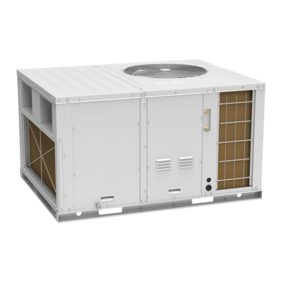
Page 5: Product Introduction
① Above pictures may be different from actual model. ② 1Ton =12000Btu/h = 3.517kW. 2 NOMENCLATURE - Description Options Product Category GK=GREE Rooftop Packaged Air-condition C = Cooling only type; Product Function Code H = Heat pump type. 03=3Ton; Cooling/Heating Capacity 5.5=5.5Ton.. -
Page 6: Function
With compact and unitary structure, the unit can be connected and assembled at field, SPACE SAVING which is in favor of transport and installation and saves indoor space. 4 PRODUCT DATA 4.1 PRODUCT DATA AT RATED CONDITION Model GK-H03NH3AS GK-H5.5NH3AS Btu/h 35800(13650-42660) 66500(20500-66500) Cooling 10.5(4.0-12.5) - Page 7 GREE ROOFTOP PACKAGED SERVICE MANUAL Model GK-H03NH3AS GK-H5.5NH3AS Fins per Inch(FPI) Drain Connection Size Inch 0.80×0.047 0.80×0.047 Type Inverter Rotary Inverter Rotary Compressor Quantity Drive Type Direct Drive Direct Drive Fan motor Power Output Type Axial-flow Axial-flow Condenser Quantity Side...
- Page 8 GREE ROOFTOP PACKAGED SERVICE MANUAL Model GK-H5.5NH3AF GK-H10NH3AF Type Centrifugal Centrifugal Quantity Motor Speed 1080 1400 Copper tube- Copper tube- Material Aluminum fin Aluminum fin sq.ft 4.31 7.00 Evaporator Face Area 0.65 Fins per Inch(FPI) Drain Connection Size Inch 0.80×0.047 0.80×0.047...
-
Page 9: Operation Range
GREE ROOFTOP PACKAGED SERVICE MANUAL 4.2 OPERATION RANGE GK-H03NH3AS、GK-H5.5NH3AS 、GK-H5.5NH3AF、GK-H10NH3AF Item Outdoor Condition (DB ° C) Cooling 18~48 Heating -10~24 4.3 ELECTRICAL DATA Condenser Supply Blower Compressor Breaker Min. Power Fan Motors Motor Capacity Supply Cord Model Power Supply Qty. - Page 10 GREE ROOFTOP PACKAGED SERVICE MANUAL CONTROL...
-
Page 11: Units Control
GREE ROOFTOP PACKAGED SERVICE MANUAL UNITS CONTROL 1 OPERATION FLOWCHART 1.1 COOLING OPERATION Power Open unit running at cool mode Indoor fan run Satisfying open Comp. condition Comp. and outdoor fan run Temp of indoor ≤Set temp Comp. and outdoor fan stop Comp. -
Page 12: Heating Operation
GREE ROOFTOP PACKAGED SERVICE MANUAL 1.2 HEATING OPERATION... -
Page 13: Wireless Remote Controller
GREE ROOFTOP PACKAGED SERVICE MANUAL 2 WIRELESS REMOTE CONTROLLER Notes: The wireless remote controller is an Optional Fitting 2.1 OPERATION AND DISPLAY VIEW Table 2-2-1 Operation instruction of wireless remote controller Name Function Description Signal Signal transmitter transmitter ON/OFF Press this button and the unit will be turned on; press it once more, and the unit will be turned off. - Page 14 GREE ROOFTOP PACKAGED SERVICE MANUAL Name Function Description By pressing this button, Auto, Low, Middle, High speed can be circularly selected. After power on, Auto fan speed is default. Low speed FAN button Middle speed High speed Note: Under the DRY mode, the fan will be kept running at the low speed and the fan speed isn't adjustable.
-
Page 15: Wired Controller
GREE ROOFTOP PACKAGED SERVICE MANUAL 3 WIRED CONTROLLER 3.1 DISPLAY VIEW Figure 2-3-1 Appearance of wired controller Figure 2-3-2 LCD display of wired controller Table 2-3-1 Instruction to LCD Display Display Introduction Automatic mode (under auto mode, the indoor unit will select its operating mode... -
Page 16: Operation View
GREE ROOFTOP PACKAGED SERVICE MANUAL Display Introduction Sleep Display when sleep function is set (only display sleep mode II) Exchange Display when air exchange function is set Silent Display when silent function is set (only display silent, no AT) Health... - Page 17 GREE ROOFTOP PACKAGED SERVICE MANUAL 3.2.2 Instruction to Function of Buttons Table 2-3-2 Instruction to buttons of wired controller Description Functions Function selection and canceling; Press it for 5s to view the ambient temperature; press Mode button to...
-
Page 18: Operation Instructions Of Special Functions
GREE ROOFTOP PACKAGED SERVICE MANUAL 4 OPERATION INSTRUCTIONS OF SPECIAL FUNCTIONS 4.1 Setting of Filter Clean Reminder Function When unit is on, press Function button to switch to filter clean reminder function. The icon will blink and then enter setting of filter clean reminder function. Timer zone displays the set pollution level and you can press ▲... -
Page 19: Lock Function
GREE ROOFTOP PACKAGED SERVICE MANUAL (1) If cleaning time is not reached, no mater the setting is changed or not, the accumulated operating time won’t be recalculated when pressing Swing/Enter button; (2) If cleaning time is reached, in unit on or off state, will blink every 0.5s for reminder. -
Page 20: Switch Between Fahrenheit And Centigrade
GREE ROOFTOP PACKAGED SERVICE MANUAL 4.5 Switch between Fahrenheit and Centigrade Under off state of the unit, press Mode and ▼ buttons at the same time for 5s to switch between Fahrenheit and Centigrade. 4.6 Enquiry of Ambient Temperature Under off or on state of the unit, press Swing/Enter for 5s to view the ambient temperature. In this case, timer zone displays ambient temperature type 01 or 02. - Page 21 GREE ROOFTOP PACKAGED SERVICE MANUAL 4.8.2 Displaying setting of freeze protection error code Under debugging state, press Mode button to adjust to “02” in temperature displaying zone. Timer zone displays setting state and press ▲ or ▼ button to adjust. There are 2 selections:...
- Page 22 GREE ROOFTOP PACKAGED SERVICE MANUAL 4.8.6 Selecting low-power consumption mode Under debugging state, press Mode button to adjust to “07” in temperature displaying zone. Timer zone displays setting state and press ▲ or ▼ button to adjust. There are 2 selections:...
- Page 23 GREE ROOFTOP PACKAGED SERVICE MANUAL 4.8.10 Selecting compensation of temperature sensor at air return Under debugging state, press Mode button to adjust to “12” in temperature displaying zone. Timer zone displays setting state and press ▲ or ▼ button to adjust. There are 16 selections: (1).
-
Page 24: Installation Of Wired Controller
GREE ROOFTOP PACKAGED SERVICE MANUAL 5 INSTALLATION OF WIRED CONTROLLER 5.1 Standard Accessories Table 2-5-1 Standard Accessories of Wired Controller ① ② ③ ④ junction box for installing Name wired controller screw M4×25 installing box of wired controller inside the wall... -
Page 25: Installation Of Wired Controller
GREE ROOFTOP PACKAGED SERVICE MANUAL 5.3 Installation of Wired Controller First to select the right signal wire of wired controller: 2–core signal wire (wire diameter>=0.75mm, length<30m, recommendable length is 8m). For installation steps of wired controller please refer to the following sketch map, brief instructions are... -
Page 26: Troubleshooting
GREE ROOFTOP PACKAGED SERVICE MANUAL 6 TROUBLESHOOTING 6.1 DISPLAY OF ERROR CODE Table 2-6-1 Error Code List 1 Error code Error Remarks Compressor high pressure protection Indoor anti-freeze protection Compressor low pressure protection, refrigerant lack protection and refrigerant colleting mode... - Page 27 GREE ROOFTOP PACKAGED SERVICE MANUAL Error code Error Remarks DRED1 mode DRED2 mode DRED3 mode Water overflow protection Emergency Stop(Fire alarm) Note: When several malfunctions occur at the same time, these error codes will be displayed circularly. When there is a malfunction, please turn off the unit and ask the professional for maintenance.
- Page 28 GREE ROOFTOP PACKAGED SERVICE MANUAL INSTALLATION...
-
Page 29: Installation
GREE ROOFTOP PACKAGED SERVICE MANUAL INSTALLATION 1 UNITS INSTALL 1.1 INSTALLATION POSITIONS To ensure the unit in proper function, selection of installation location must be in accordance with following principles. (1) Unit shall be installed so that the air discharged by outdoor fan will not return and that sufficient space for repair shall be provided around the unit. - Page 30 And the unit must be fixed on the pedestal with bolt. The location of pedestal must be able to support the weight of the unit. If not, the unit may be overturning, declining or falling off in an extreme circumstance (just like earthquake, typhoon). GK-H03NH3AS...
- Page 31 GREE ROOFTOP PACKAGED SERVICE MANUAL GK-H5.5NH3AS、GK-H5.5NH3AF GK-H10NH3AF NOTE: ① The diagram may be different from actual model. The diagram is for pedestal made of concrete. ② The high dimension of the pedestal must be enough to install drainpipe (Refer to DRAIN PIPING WORK) 1.2.4 DUCTWORK...
-
Page 32: Dimension
Each installation must include a return air filter. This filtering may be performed at the unit or externally such as a return air filter grille. Building condition and maintenance convenience should be taken into consideration when selecting the installation method. 1.3 DIMENSION 1.3.1 DIMENSION OF UNITS GK-H03NH3AS GK-H5.5NH3AS、GK-H5.5NH3AF... - Page 33 GREE ROOFTOP PACKAGED SERVICE MANUAL GK-H10NH3AF Dimension (mm) GK-H03NH3AS 1450 1120 GK-H5.5NH3AS 1450 1120 GK-H5.5NH3AF 1450 1120 GK-H10NH3AF 1215 1450 1120 Note: Above diagrams may be different from actual mode. 1.3.2 INSTALLATION CLEARANCE DATA Note: Above diagrams may be different from actual mode.
-
Page 34: Drain Piping Work
GREE ROOFTOP PACKAGED SERVICE MANUAL GK-H03NH3AS、GK-H5.5NH3AS、GK-H5.5NH3AF Installation Clearances DIMENSION (Minimum) inch 1100 1100 1100 Note: Above diagrams may be different from actual mode. GK-H10NH3AF Installation Clearances DIMENSION (Minimum) inch 1000 1500 1100 1100 1100 2 DRAIN PIPING WORK 2.1 INSTALLATION PROCEDURE After the unit is installed, it is required to check the level of the whole unit. -
Page 35: Matters Of Attention
Remark: P is the absolute pressure inside the unit. The unit of the pressure is Pa. After the electrical installation is completed, carry out the testing of the drainage system. Note: Above diagrams may be different from actual mode. Model Drain Connection Size(mm) GK-H03NH3AS GK-H5.5NH3AS GK-H5.5NH3AF GK-H10NH3AF 3 ELECTRIC WIRING WORK 3.1 WIRING PRINCIPLE... - Page 36 GREE ROOFTOP PACKAGED SERVICE MANUAL (7) Do not let any cable contact the refrigerant pipe, the compressor and moving parts such as fan. (8) Do not change the internal line connections inside the air-conditioning unit. The manufacturer shall not be liable for any loss or abnormal operation arising from wrong line connections.
-
Page 37: Electric Wiring Design
The signal line of the wire controller must be separated from the power line. In case the unit is installed in a place vulnerable by electromagnetic interference, it is better to use shielded cable or double-twisted cable as the signal line of the wire controller. 3.2 ELECTRIC WIRING DESIGN GK-H03NH3AS、GK-H5.5NH3AS GK-H5.5NH3AF、GK-H10NH3AF... - Page 38 GREE ROOFTOP PACKAGED SERVICE MANUAL MAINTENANCE...
-
Page 39: Maintenance
GREE ROOFTOP PACKAGED SERVICE MANUAL MAINTENANCE 1 MALFUNCTION TABLE 1.1 MAIN CONTROL MALFUNCTION Table 1 Fault Display on Wired Controller Origin of Error Malfunction malfunction Control description code name signal When unit detects the high pressure switch is cut off for 3s successively, high pressure protection will occur. - Page 40 GREE ROOFTOP PACKAGED SERVICE MANUAL Origin of Error Malfunction malfunction Control description code name signal temperature temperature sensor malfunction will be reported. The unit can automatically sensor at air sensor resume operation after the malfunction disappears. If indoor return port ambient temperature sensor malfunction occurs in fan mode, only the error code is displayed and the unit can work normally.
-
Page 41: Description Of Drive Malfunction
GREE ROOFTOP PACKAGED SERVICE MANUAL Origin of Error Malfunction malfunction Control description code name signal After the compressor starts operation in heating mode, if the unit detects the difference between evaporator temperature and indoor ambient temperature is lower than the protective value for 10min... -
Page 42: Flow Chart Of Troubleshooting
GREE ROOFTOP PACKAGED SERVICE MANUAL Malfunction Item Wired Controller Display Unit display of dual 8 numeral tube Condenser Fan current protection Condenser Fan power protection Condenser Fan Current sensor malfunction Condenser Fan motor in loss of synchronization Malfunction from Condenser Fan driving part to... - Page 43 GREE ROOFTOP PACKAGED SERVICE MANUAL E2 Freeze Protection Freeze protection is normal protection but not abnormal malfunction. If freeze protection occurs frequently during operation, please check if the indoor filter is with filth blockage or if the indoor air outlet is abnormal.
- Page 44 GREE ROOFTOP PACKAGED SERVICE MANUAL E4 Discharge Protection E4 protection Replace the discharge temperature sensor Check if the discharge Check if the temperature around discharge Replace the outdoor compressor discharge temperature sensor main control board temperature sensor is normal exceeds 115℃...
- Page 45 GREE ROOFTOP PACKAGED SERVICE MANUAL F0 Malfunction of Indoor Ambient Temperature Sensor Malfunction of indoor ambient temperature sensor Check if the indoor ambient temperature Correctly insert the sensor on mainboard is inserted temperature sensor on the needle on the needle stand...
- Page 46 GREE ROOFTOP PACKAGED SERVICE MANUAL F2 Malfunction of Condenser Temperature Sensor Malfunction of condenser temperature sensor Check if the condenser Correctly insert the temperature sensor on temperature sensor mainboard is inserted on the on the needle stand needle stand correctly...
- Page 47 GREE ROOFTOP PACKAGED SERVICE MANUAL F4 Malfunction of Discharge Temperature Sensor Malfunction of discharge temperature sensor Check if the Correctly insert the discharge temperature sensor on temperature sensor mainboard is inserted on the on the needle stand needle stand correctly...
- Page 48 GREE ROOFTOP PACKAGED SERVICE MANUAL H6 Malfunction of Outdoor Fan Motor Malfunction of Outdoor Fan Motor Check if the Correctly connect the control wire of outdoor fan motor is control wire of fan motor connected on the outdoor on the mainboard...
-
Page 49: Troubleshooting Flow Chart Of Drive Malfunction
GREE ROOFTOP PACKAGED SERVICE MANUAL 2.2 TROUBLESHOOTING FLOW CHART OF DRIVE MALFUNCTION P0 Drive module reset P7 IPM temperature sensor error PA AC current protection (input side) PC Current sense circuit error P0、P7、PA or PC is... - Page 50 GREE ROOFTOP PACKAGED SERVICE MANUAL P6 Drive-to-main-control communication error Lc Compressor Startup Failure P5 Compressor current protection H7 Compressor motor desynchronizing H5 IPM protection Ld Phase loss P5, H7, H5 or Ld is displayed...
- Page 51 GREE ROOFTOP PACKAGED SERVICE MANUAL ee driving board chip error H6 DC fan error H6 is displayed on the wired controller H6 is displayed in the mainboard 88 indicating lamp Is the motor phase sequence Adjust the motor...
-
Page 52: Wiring Diagram
GREE ROOFTOP PACKAGED SERVICE MANUAL 3 WIRING DIAGRAM The actual wiring should always refer to the wiring diagram of the unit. Model: GK-H03NH3AS Note: Above data is subject to change without notice. - Page 53 GREE ROOFTOP PACKAGED SERVICE MANUAL Model: GK-H5.5NH3AS Note: Above data is subject to change without notice.
- Page 54 GREE ROOFTOP PACKAGED SERVICE MANUAL Model: GK-H5.5NH3AF Note: Above data is subject to change without notice.
- Page 55 GREE ROOFTOP PACKAGED SERVICE MANUAL Model: GK-H10NH3AF Note: Above data is subject to change without notice.
-
Page 56: Disassembly And Assembly Procedure Of Main Parts
ROOFTOP PACKAGED SERVICE MANUAL 4 DISASSEMBLY AND ASSEMBLY PROCEDURE OF MAIN PARTS 4.1 Model: GK-H03NH3AS Disassembly and Assembly of Compressor Remark: Make sure there isn't any refrigerant in pipe system and the power supply is cut off before removal of the compressor. - Page 57 GREE ROOFTOP PACKAGED SERVICE MANUAL Disassembly and Assembly of Compressor Remark: Make sure there isn't any refrigerant in pipe system and the power supply is cut off before removal of the compressor. Step Illustration Handling Instruction Unscrew the nuts on compressor base with 5.
- Page 58 GREE ROOFTOP PACKAGED SERVICE MANUAL Disassembly and Assembly of Compressor Remark: Make sure there isn't any refrigerant in pipe system and the power supply is cut off before removal of the compressor. Step Illustration Handling Instruction Connect refrigerant tank with nozzle of low pressure (indicated by the maker) for 10.
- Page 59 GREE ROOFTOP PACKAGED SERVICE MANUAL Disassembly and Assembly of Condenser Fan Motor Remark: Make sure that the unit is stopped running and power supply is cut off before removal of the motor. Step Illustration Handling Instruction Remove the holding bolt of motor 4.
- Page 60 GREE ROOFTOP PACKAGED SERVICE MANUAL Disassembly and Assembly of Condenser Fan Motor Remark: Make sure that the unit is stopped running and power supply is cut off before removal of the motor. Step Illustration Handling Instruction Re-connect power cord according to circuit mark adhered on eletric box.
- Page 61 GREE ROOFTOP PACKAGED SERVICE MANUAL Disassembly and Assembly of Supply Blower Motor Remark: Make sure that the unit is stopped running and power supply is cut off before removal of the motor. Step Illustration Handling Instruction 4. Remove the Remove the fan volute.
- Page 62 GREE ROOFTOP PACKAGED SERVICE MANUAL Disassembly and Assembly of Electric Box Remark: Make sure that the unit is stopped running and power supply is cut off before removal. Step Illustration Handling Instruction Unscrew the screws fixing side 1. Take down the plate.
- Page 63 GREE ROOFTOP PACKAGED SERVICE MANUAL Disassembly and Assembly of Electric Box Remark: Make sure that the unit is stopped running and power supply is cut off before removal. Step Illustration Handling Instruction Put the electric box back and tighten the screws. Then reconnect...
- Page 64 GREE ROOFTOP PACKAGED SERVICE MANUAL 4.2 Model: GK-H5.5NH3AS、GK-H5.5NH3AF Model: GK-H5.5NH3AS、GK-H5.5NH3AF Disassembly and Assembly of Compressor -Remark: Make sure there isn't any refrigerant in pipe system and the power supply is cut off before removal of the compressor. Step Illustration Handling Instruction...
- Page 65 GREE ROOFTOP PACKAGED SERVICE MANUAL Disassembly and Assembly of Compressor -Remark: Make sure there isn't any refrigerant in pipe system and the power supply is cut off before removal of the compressor. Step Illustration Handling Instruction Unscrew the nuts on compressor base 5.
- Page 66 GREE ROOFTOP PACKAGED SERVICE MANUAL Disassembly and Assembly of Compressor -Remark: Make sure there isn't any refrigerant in pipe system and the power supply is cut off before removal of the compressor. Step Illustration Handling Instruction Connect refrigerant tank with nozzle of low pressure (indicated by the maker) for 10.
- Page 67 GREE ROOFTOP PACKAGED SERVICE MANUAL Disassembly and Assembly of Condenser Fan Motor Remark: Make sure that the unit is stopped running and power supply is cut off before removal of the motor. Step Illustration Handling Instruction Remove the holding bolt of 4.
- Page 68 GREE ROOFTOP PACKAGED SERVICE MANUAL Disassembly and Assembly of Condenser Fan Motor Remark: Make sure that the unit is stopped running and power supply is cut off before removal of the motor. Step Illustration Handling Instruction Re-connect power cord according to circuit mark adhered on eletric box.
- Page 69 GREE ROOFTOP PACKAGED SERVICE MANUAL Disassembly and Assembly of Supply Blower Motor Remark: Make sure that the unit is stopped running and power supply is cut off before removal of the motor. Step Illustration Handling Instruction 4. Remove the Unscrew the screws fixing cover...
- Page 70 GREE ROOFTOP PACKAGED SERVICE MANUAL Disassembly and Assembly of Supply Blower Motor Remark: Make sure that the unit is stopped running and power supply is cut off before removal of the motor. Step Illustration Handling Instruction hermetically. 9. Re-install the...
- Page 71 GREE ROOFTOP PACKAGED SERVICE MANUAL Disassembly and Assembly of Electric Box Remark: Make sure that the unit is stopped running and power supply is cut off before removal. Step Illustration Handling Instruction Disconnect connection lines between exterior electric component and elements in electric box.
- Page 72 GREE ROOFTOP PACKAGED SERVICE MANUAL Disassembly and Assembly of Electric Box Remark: Make sure that the unit is stopped running and power supply is cut off before removal. Step Illustration Handling Instruction 9. Re-install the Put the side plate back and tighten side plate.
- Page 73 GREE ROOFTOP PACKAGED SERVICE MANUAL Disassembly and Assembly of Compressor Remark: Make sure there isn't any refrigerant in pipe system and the power supply is cut off before removal of the compressor. Step Illustration Handling Instruction Heat the connection pipes indicated by 4.
- Page 74 GREE ROOFTOP PACKAGED SERVICE MANUAL Disassembly and Assembly of Compressor Remark: Make sure there isn't any refrigerant in pipe system and the power supply is cut off before removal of the compressor. Step Illustration Handling Instruction 9. Re-install the cover Put the cover plate back and tighten the plate.
- Page 75 GREE ROOFTOP PACKAGED SERVICE MANUAL Disassembly and Assembly of Condenser Fan Motor Remark: Make sure that the unit is stopped running and power supply is cut off before removal of the motor. Step Illustration Handling Instruction Unscrew the nuts (indcated by the arrow) fixing fan to take the fan out.
- Page 76 GREE ROOFTOP PACKAGED SERVICE MANUAL Disassembly and Assembly of Condenser Fan Motor Remark: Make sure that the unit is stopped running and power supply is cut off before removal of the motor. Step Illustration Handling Instruction Re-install fan blade and screw...
- Page 77 GREE ROOFTOP PACKAGED SERVICE MANUAL Disassembly and Assembly of Supply Blower Motor Remark: Make sure that the unit is stopped running and power supply is cut off before removal of the motor. Step Illustration Handling Instruction Unscrew the screws fixing cover 1.
- Page 78 GREE ROOFTOP PACKAGED SERVICE MANUAL Disassembly and Assembly of Supply Blower Motor Remark: Make sure that the unit is stopped running and power supply is cut off before removal of the motor. Step Illustration Handling Instruction Unscrew the holding screw of fan...
- Page 79 GREE ROOFTOP PACKAGED SERVICE MANUAL Disassembly and Assembly of Supply Blower Motor Remark: Make sure that the unit is stopped running and power supply is cut off before removal of the motor. Step Illustration Handling Instruction 7. Fix the fan...
- Page 80 GREE ROOFTOP PACKAGED SERVICE MANUAL Disassembly and Assembly of Electric Box Remark: Make sure that the unit is stopped running and power supply is cut off before removal. Step Illustration Handling Instruction Unscrew the screws fixing side plate. 1. Take down the...
- Page 81 GREE ROOFTOP PACKAGED SERVICE MANUAL Disassembly and Assembly of Electric Box Remark: Make sure that the unit is stopped running and power supply is cut off before removal. Step Illustration Handling Instruction Unscrew the screws (indicated by the arrows),and then take down the 5.
- Page 82 GREE ROOFTOP PACKAGED SERVICE MANUAL Disassembly and Assembly of Electric Box Remark: Make sure that the unit is stopped running and power supply is cut off before removal. Step Illustration Handling Instruction Re-connect power cord according to wiring diagram adhered on eletric box.
-
Page 83: Exploded Views And Spare Part List
GREE ROOFTOP PACKAGED SERVICE MANUAL 5 EXPLODED VIEWS AND SPARE PART LIST Model: GK-H03NH3AS GK-H03NH3AS Name of Part Product Code EJ51000660 Part Code Quantity Main Board '300027060219 Main Board '30221000026 Radiator 430034000014 Main Board '300002060345 Main Board '30223000046 Radiator... - Page 84 GREE ROOFTOP PACKAGED SERVICE MANUAL GK-H03NH3AS Name of Part Product Code EJ51000660 Part Code Quantity Electric Box Assy '100002061827 Air Outlet Panel '012233060008P Filter Sub-Assy '11100100000602 Evaporator Assy '011001060257 Clapboard Sub-Assy '017021060114P Filter Sub-Assy 111001000086 Side Plate '017110060027P Side Plate...
- Page 85 GREE ROOFTOP PACKAGED SERVICE MANUAL Model: GK-H5.5NH3AS GK-H5.5NH3AS Name of Part Product Code EJ51000740 Part Code Quantity Radiator '430034000004 ‘300027060479 Main Board Power Switch '300012060010 Radiator '49018000001 ’30223000046 Main Board ‘300027060219 Main Board Filter Board '300020000003 Terminal Board '422000060003...
- Page 86 GREE ROOFTOP PACKAGED SERVICE MANUAL GK-H5.5NH3AS Name of Part Product Code EJ51000740 Part Code Quantity Filter Sub-Assy '11100100000602 Evaporator Assy '011001060249 Clapboard Sub-Assy '017021060114P Side Plate '017110060027P Side Plate '017110060026P Handle '26235253 Rear Grill '016001060024 Filter Sub-Assy '111001000086 Water Tray Sub-Assy...
- Page 87 GREE ROOFTOP PACKAGED SERVICE MANUAL Model: GK-H5.5NH3AF GK-H5.5NH3AF Name of Part Product Code EJ51000650 Part Code Quantity Radiator '4901800000201 Main Board '300027060204 Reactor '43138000049 Rectifier '46010604 AC Contactor '44010265 Radiator '49018000001 Main Board '30223000046 Filter Board '30228000032 Terminal Board...
- Page 88 GREE ROOFTOP PACKAGED SERVICE MANUAL GK-H5.5NH3AF Name of Part Product Code EJ51000650 Part Code Quantity Side Plate '017110060026P Handle '26235253 Clapboard Sub-Assy '017021060114P Water Tray Sub-Assy '017055060072P Base Plate Sub-Assy '017000060116P Gas-Liquid Separator 07423902 Compressor and Fittings 00209400005 Choke Plug of Drain Pipe...
- Page 89 GREE ROOFTOP PACKAGED SERVICE MANUAL Model: GK-H10NH3AF GK-H10NH3AF Name of Part Product Code EJ51000710 Part Code Quantity Filter Sub-Assy '11100100000603 Handle '26235253 Side Plate '017110060045P Side Plate '017110060044P Rear Grill '016001060029 Air Outlet Panel Sub-Assy '017097060008P Choke Plug of Drain Pipe...
- Page 90 GREE ROOFTOP PACKAGED SERVICE MANUAL GK-H10NH3AF Name of Part Product Code EJ51000710 Part Code Quantity Nozzle for Adding Freon '06130002 Compressor and Fittings '009001060108 Gas-Liquid Separator '07424188 Base Frame Assy '000043060104 Pressure Switch '4602001531 4-Way Valve '43000339 Condenser Assy '011002060387...
- Page 91 JF00303727...
Need help?
Do you have a question about the GK-H03NH3AS and is the answer not in the manual?
Questions and answers